Series
Module [s]
EOL Module [e]
Product
Option [o]
GNEXCP7-BG[s][t][l][e][m][d][v][o][x][u]-[v][e][s]
Product
Version [v]
LED Indicator [u]
Switch Type [s]
Terminals [t]
2S
EUROPEAN SAFETY SYSTEMS LTD
IMPRESS HOUSE
MANSELL ROAD
ACTON
LONDON W3 7QH
WWW.E2S.COM
C
THIS DRAWING AND ANY INFORMATION OR DESCRIPTIVE
MATTER THEREIN IS COMMUNICATED IN CONFIDENCE AND
IS THE COPYRIGHT PROPERTY OF EUROPEAN SAFETY
SYSTEMS LTD. NEITHER THE WHOLE OR ANY EXTRACT MAY
BE DISCLOSED, LOANED, COPIED OR USED FOR
MANUFACTURING OR TENDERING PURPOSES WITHOUT THEIR
WRITTEN CONSENT.
EUROPEAN SAFETY SYSTEMS LTD.
AS PER LATEST DATE OF ISSUE SHOWN ABOVE
DRAWING TO BS8888:2000
GEOMETRIC TOLERANCES TO ISO1101:1983
LINEAR DIMENSIONAL TOLS
ANGULAR DIMENSIONAL TOLS
STANDARDS
MOD No. REASON - INITIAL - DATEISSUE
DATE
APPROVED
CHECKED DATE
DATE
DRAWN WEIGHT (Kg)
SURFACE FINISH
MATERIAL
ALTERNATIVE MATERIAL SHEETSCALE
TITLE
A3
IF IN DOUBT, ASK -
DO NOT SCALE
ALL DIMENSIONS IN MM
DRAWING NUMBER
A
B
C
D
E
F
G
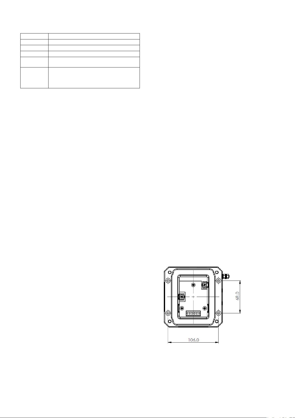
109
G
F
E
78
6
5
D
C
134
2
A
B
D202-06-211
R.S.RAIT
B.ISARD
R.N.POTTS
05-03-2020
OF
GNExCP7 ; STExCP8 ; WP7 CALL POINT
WIRING / CIRCUIT OPERATION DIAGRAM
NTS 1 8
05-03-2020
05-03-2020
Addition of BG version ; Options clarified
RNP 15-04-2022
5ACN0102
6Configuration coding added and aligned with other call points.
LED options added ; PCB page moved to new document.
RNP 14-07-2023
ACN0127
warning signals
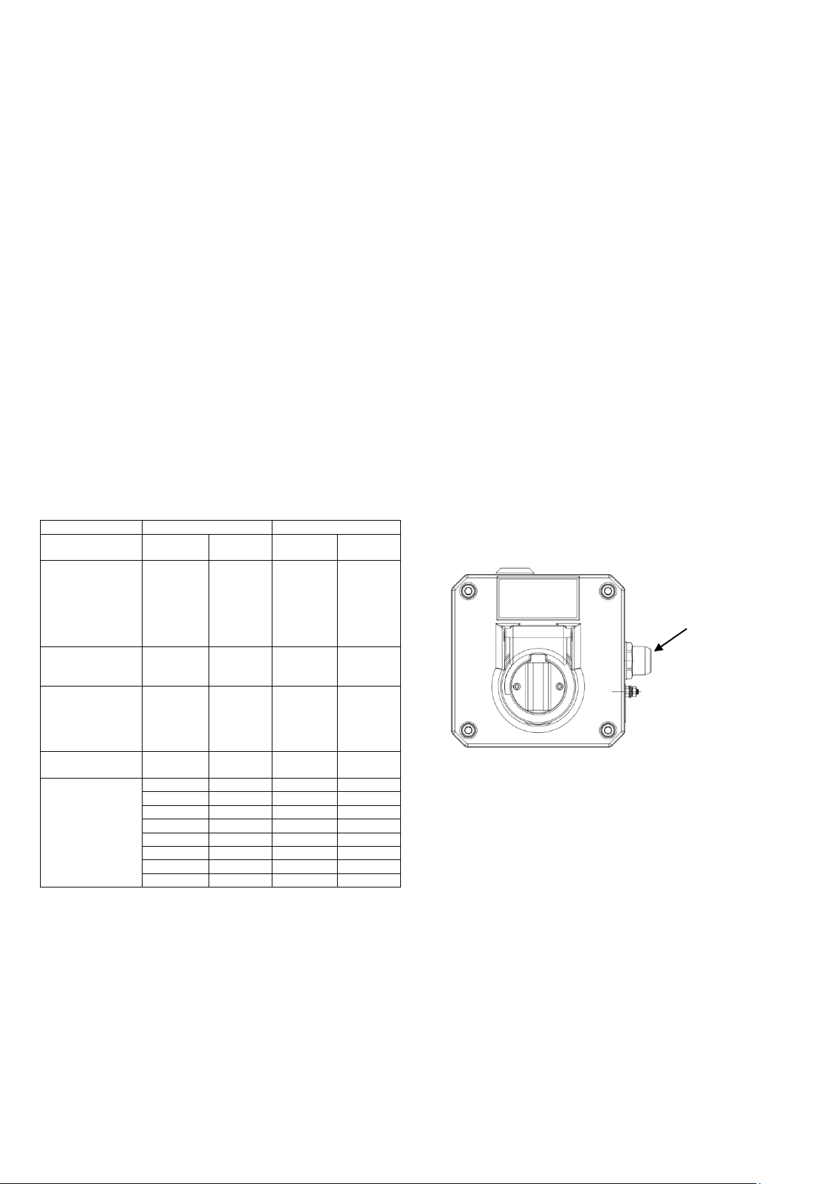
GNExCP7 ; STExCP8 ; WP7 units
with DIN Rail
Module Device Codes
EOL Series
Resistor ExxxR SxxxR
Diode ED1 SD1
Zener Diode ExxxZ SxxxZ
LED N/A L or C
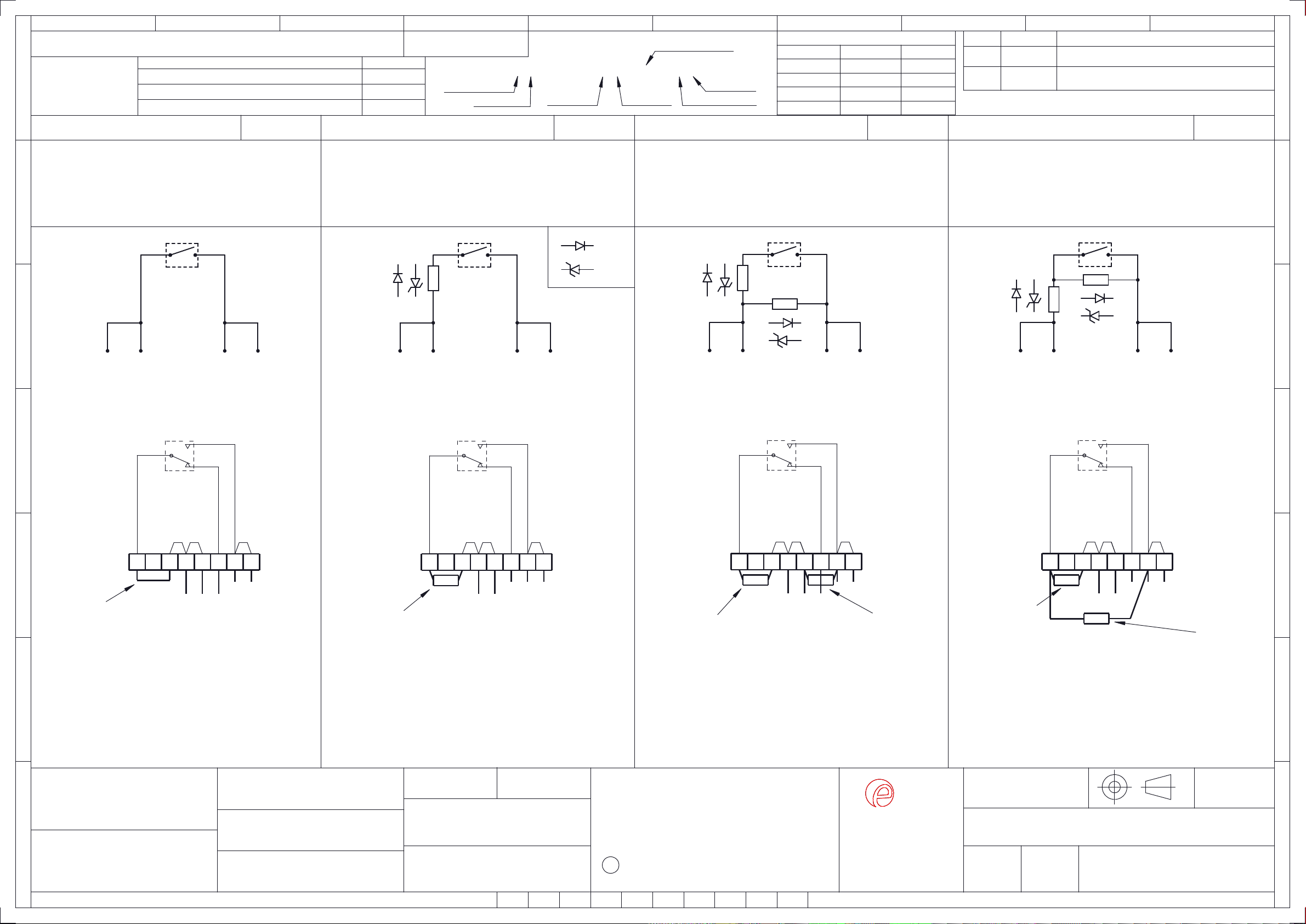
SINGLE MICROSWITCH DEVICES
SINGLE SWITCH WITH SERIES DEVICE
SWITCH TYPE [s]
TERMINALS [t]
PRODUCT OPTION [o]
LED INDICATOR [u]
SINGLE SWITCH CONFIG. D1-1 CONFIG. D1-2 SINGLE SWITCH WITH EOL & SERIES DEVICES
SWITCH TYPE [s]
TERMINALS [t]
PRODUCT OPTION [o]
LED INDICATOR [u]
MODULES [e][s]
SINGLE SWITCH WITH EOL & ALT. SERIES DEVICES
SWITCH TYPE [s]
TERMINALS [t]
PRODUCT OPTION [o]
LED INDICATOR [u]
MODULE [e][s]
CONFIG. D1-3 CONFIG. D1-4
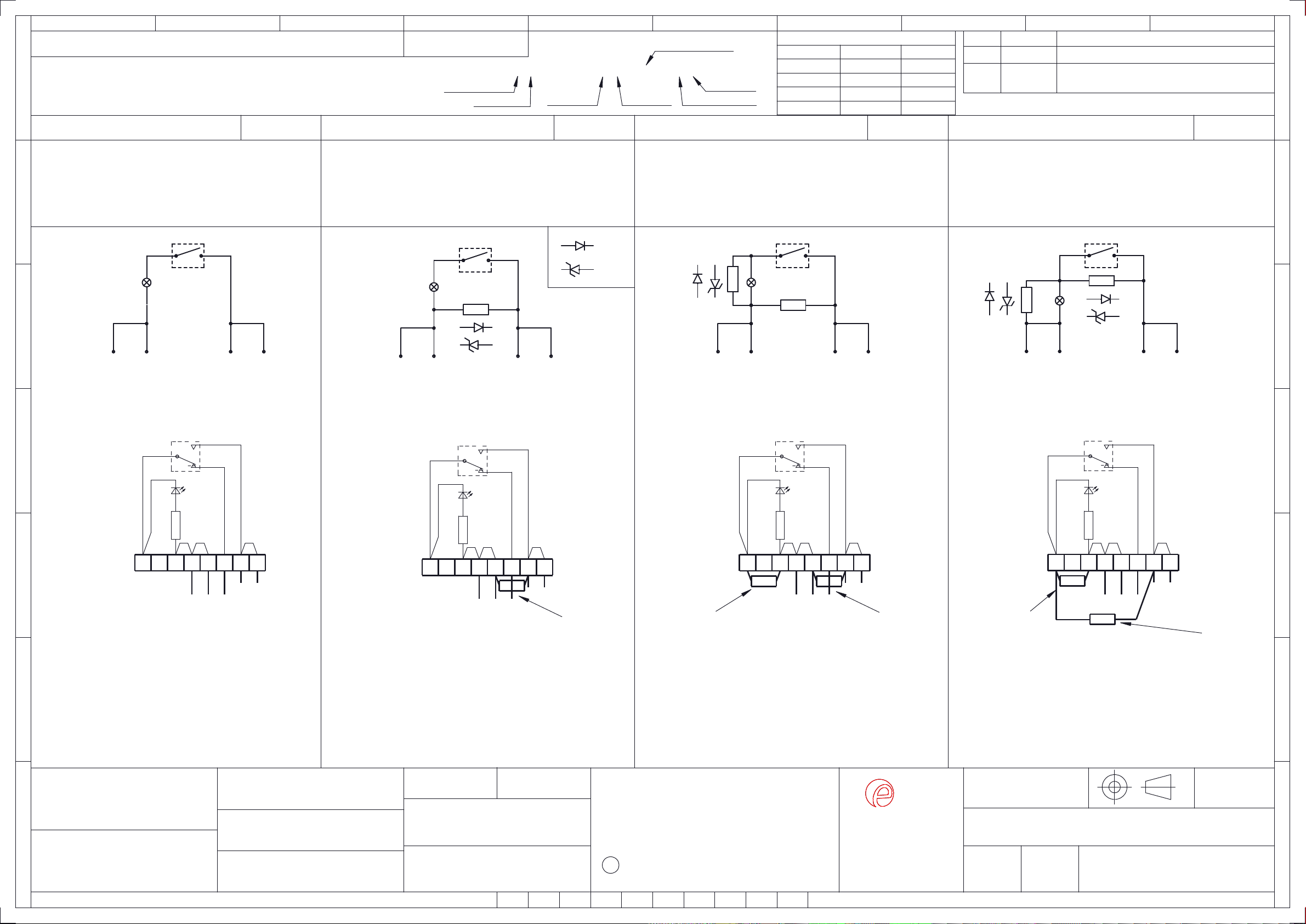
Diagram Sheet
Dual Switch Wiring Configurations 2,3,5,6,7,8
LED Indicator Wiring Configurations 4,5,6,8
Parallel Dual Switch Wiring Configurations 7, 8
[S]
[D]
[1]
[N]
SWITCH TYPE [s]
TERMINALS [t]
PRODUCT OPTION [o]
LED INDICATOR [u]
SERIES MODULE [s]
Single
DIN Rail
Default
NO LED
[S]
[D]
[1]
[N]
[Sxxxx]
Single
DIN Rail
Default
NO LED
Series Device
[S]
[D]
[1]
[N]
[Exxxx][Sxxxx]
Single
DIN Rail
Default
NO LED
EOL + Series
[S]
[D]
[W]
[N]
[Exxxx][Sxxxx]
Single
DIN Rail
Alt. EOL Pos'n.
NO LED
EOL + Series
SHEET 1
PRODUCTS:
GNExCP7, STExCP8
& WP7
Circuit shown in Unoperated condition
Unoperated condition
(Glass Intact / Standby Condition)
Terminals +(4,5) & -(7,8) open
Terminals +(4,5) & (6) closed
Operated condition
(Glass Broken / Button pushed in)
Terminals +(4,5) & -(7,8) closed
Terminals +(4,5) & (6) open
M/S 1
-
+
COM
-
+
87654321
N/O
4
+
5
+
7
-
8
-
87654321
N/C N/O
Circuit shown in Unoperated condition
Unoperated condition
(Glass Intact / Standby Condition)
Terminals +(4,5) & -(7,8) open
Terminals +(4,5) & (6) closed
Operated condition
(Glass Broken / Button pushed in)
Terminals +(4,5) & -(7,8) closed
Terminals +(4,5) & (6) open
M/S 1
-
+
COM
-
+
8
-
7
-
5
+
4
+
4
+
5
+
7
-
8
-
EOL
SERIES
+
SERIES
87654321
N/C N/O
Circuit shown in Unoperated condition
Unoperated condition
(Glass Intact / Standby Condition)
Terminals +(4,5) & -(7,8) open
Terminals +(4,5) & (6) closed
Operated condition
(Glass Broken / Button pushed in)
Terminals +(4,5) & -(7,8) closed
Terminals +(4,5) & (6) open
M/S 1
-
+
COM
-
COM
-
M/S 1
-
+ +
SERIES
87654321
N/C N/O
Circuit shown in Unoperated condition
Unoperated condition
(Glass Intact / Standby Condition)
Terminals +(4,5) & -(7,8) open
Terminals +(4,5) & (6) closed
Operated condition
(Glass Broken / Button pushed in)
Terminals +(4,5) & -(7,8) closed
Terminals +(4,5) & (6) open
EOL
4
+
5
+
7
-
8
-
SERIES
EOL
EOL
N/C
ZENER
DIODE
DIODE
+
+
DEVICE
POLARITY DEVICE
POLARITY
DEVICE
POLARITY
DEVICE
POLARITY
Default Link wire
replaced by Series
device in terminal Optional EOL
device
Placed as shown
in terminal
Default Link wire
replaced by
Optional Series
device in terminal
Default Link
Wire in Terminal
Note :- Use when
EOL and/or series
devices are fitted
during installation,
or if no series
devices are
required.
SERIES
Default Link wire
replaced by Series
device in terminal Optional EOL
device
Placed as shown
in terminal
SERIES
DEVICE
POLARITY
M/S 1 M/S 1 M/S 1 M/S 1