manuals.online logo
Brands
  1. Home
  2. •
  3. Brands
  4. •
  5. E2S
  6. •
  7. Security System
  8. •
  9. E2S APPELLO A121AX User manual

E2S APPELLO A121AX User manual

INSTRUCTION MANUAL
A121AX, AL121AXH, AL121AXX & MV121 APPELLO
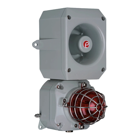
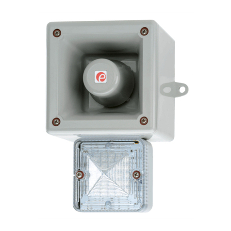
Alarm Tone and Voice Annunciation Sounder
European Safety Systems Ltd. Impress House, Mansell Road, Acton, London W3 7QH
[email protected] Tel: +44 (0)208 743 8880
www.e2s.com Fax: +44 (0)208 740 4200
Document No. D166-00-001-IS_Issue_3 16-11-22
Sheet 1 of 10
1) Introduction
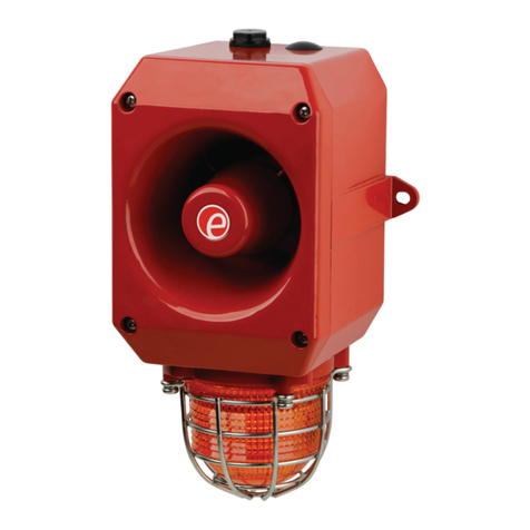
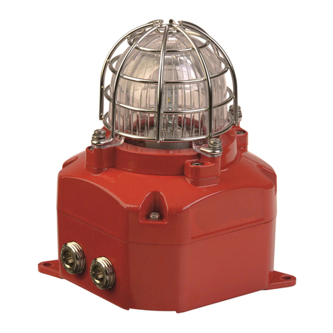
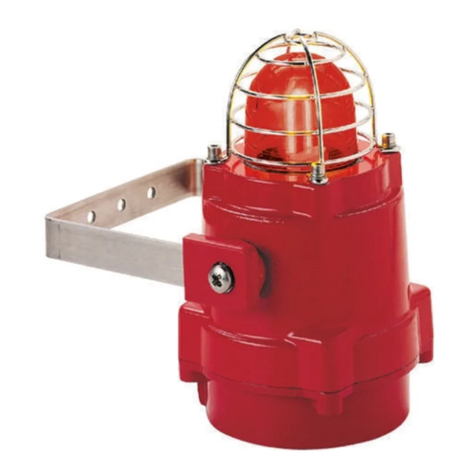
The Appello tone and speech annunciation
sounder has three different styles in AC and DC.
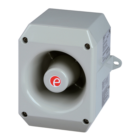
•A121AX Sounder
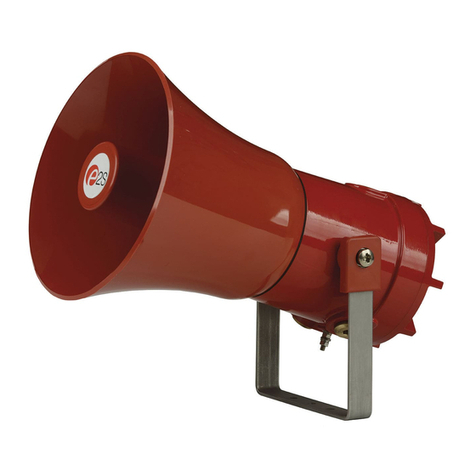
•MV121 Sounder
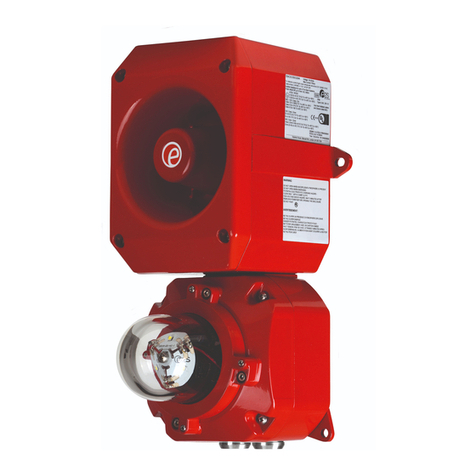
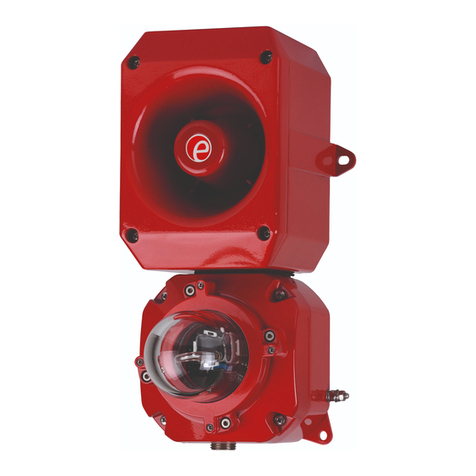
•AL121AXH High Output LED
Sounder-Beacon Combination unit
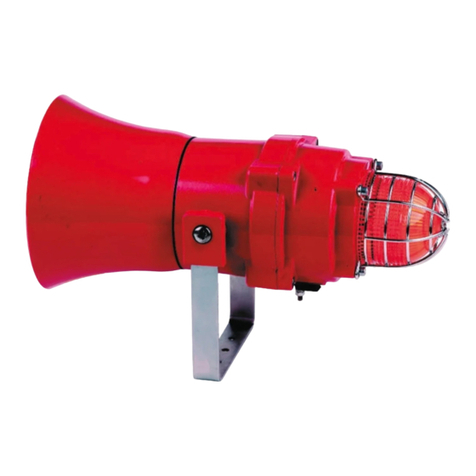
•AL121AXX Xenon Strobe
Sounder-Beacon Combination unit
These Sounder units share a common set of
functions:-
•4 stages, each stage can record up to 30
seconds of CD quality audio.
•Facility to record via an on board microphone
or a line in input.
•The recorded message can be played back
proceeded either with or without the choice
of one of forty five tones.
The Beacon functions are either:-
•Xenon Strobe - 1Hz flash rate
•LED - Either Steady or 2Hz blink rate
2) Operating and Marking
All units have the following operating
requirements and limitations.
Unit Type No. Voltage Range Current
Sounder only outputs
A121AX DC 24Vdc 14-30Vdc 1.51A
& MV121 DC
Max Current 1.85A @ 30Vdc
A121AX AC 115Vac 90-260Vac 542mA
& MV121 AC 230Vac 90-260Vac 517mA
Max Current 668mA @ 90Vac
AL121AXH / AL121AXX combined unit - Add
selected sounder & beacon currents to calculate
total current required.
Beacon only outputs
AL121AXH DC 24Vdc 10-30Vdc 157mA
Max Current 166mA @ 30Vdc
AL121AXH AC 115Vac 90-260Vac 60mA
230Vac 90-260Vac 35mA
Max Current 60mA @ 90Vac
AL121AXX DC 12Vdc 10-14Vdc 500mA
24Vdc 20-28Vdc 250mA
AL121AXX AC 115Vac +/-10%Vac 100mA
230Vac +/-10%Vac 50mA
Operating Temp: -20 to +55C
All units IP Rating: Type 4 / 4X / 3R / 13 , IP66
MV121 additional IP Rating: IP67
Marking:
3) Installation & Wiring Requirements
A121AX
AL121AXH / AL121AXX
MV121
A121AX
UNIT
AL121AXH /
AL121AXX
UNITS
MV121
UNIT
European Safety Systems Ltd. Impress House, Mansell Road, Acton, London W3 7QH
[email protected] Tel: +44 (0)208 743 8880
www.e2s.com Fax: +44 (0)208 740 4200
Document No. D166-00-001-IS_Issue_3 16-11-22
Sheet 2 of 10
Always de-energize unit before removing cover.
The installation of the units must be in
accordance with any local codes that may apply
and should only be carried out by a competent
trained electrical engineer.
The power terminals on the control unit are
clearly marked and will accept up to 1.5mm2
cable.
DC Terminals
on main PCB.
++ = Positive
- - = Negative
AC Terminals
On Sub PCB
L = Live
N = Neutral
E = Earth
The AL121 units will have the beacon already
prewired to the unit so no extra wiring is required.
4) Beacon Set-up
The beacon unit may need to be configured
dependant on the type of flash required.
The xenon beacon has a 1Hz flash rate only.
The LED beacon is set as standard to the 2Hz
flash mode but it can be set to a steady on mode
also. To alter the settings, change the position of
the header pin as shown.
•Remove header for steady mode.
•Keep header in standard position for
2Hz flashing mode
5) Unit Set-up and Recording
The unit will need to be configured to suit the end
user.
If recording either via the onboard microphone or
the in-line connector the unit will need to be
supplied with power.
DC units can be powered when completing
recording and set-up.
Warning! : During set-up on AC units care
must be taken not to touch the live terminals.
This is because on the AC units there is a risk
of electric shock.
See section 7) Appello Setup Guide overleaf for
Set-up instructions and functions.
6) Tone Selection Table
The Appello unit has 45 different tones (See
Table 1) that can be selected for the first stage
alarm. The systems can then be switched to
sound second, third and fourth stage alarm tones.
The tones are selected by operation of a DIP
switch S4 on the main PCB.
The tone table (Table 1) shows the switch
positions for the 45 tones and which tones are
available for the second third and fourth stages.
Example
S4 Dip Switch -
Shown Set for Tone 1
(All switches OFF)
To sound stage one simply connect the supply
voltage (+ve and –ve) for DC units and (L, N, E)
for AC units, to the supply input terminals on the
correct PCB shown.
European Safety Systems Ltd. Impress House, Mansell Road, Acton, London W3 7QH
[email protected] Tel: +44 (0)208 743 8880
www.e2s.com Fax: +44 (0)208 740 4200
Document No. D166-00-001-IS_Issue_3 16-11-22
Sheet 3 of 10
DC Units Second, Third and Fourth Stage
Selection
The Appello unit uses –ve switching to change
the tone to the second, third and fourth stages.
Warning! : The negative supply must remain
connected to the -(ve) terminal and a link
made from this to the appropriate stage (S2)
terminal otherwise the unit will be damaged.
To change to the second, third or fourth stage
tone, link the -ve supply line to terminal relevant
stage terminal. Ie. for Stage 2 link the -ve supply
to the S2 terminal, for Stage 3 link the -ve supply
to the S3 terminal etc.
AC Units Second, Third and Fourth Stage
Selection
The Appello unit uses Live switching to change
the tone to the second, third and fourth stages.
To change to the second, third or fourth stage
tone, whilst maintaining the ac supply to the Live
and neutral, also link the Live supply line to
terminal relevant stage terminal. i.e. for Stage 2
link the Live supply to the S2 terminal, for Stage 3
link the Live supply to the S3 terminal etc.
AL121
BEACON ON
AL121
PRE-WIRED
INTERNALLY
BEACON ON
AL121
PRE-WIRED
INTERNALLY
INSTRUCTION MANUAL
A121AX, AL121AXH, AL121AXX & MV121 APPELLO
Alarm Tone and Voice Annunciation Sounder
European Safety Systems Ltd. Impress House, Mansell Road, Acton, London W3 7QH
[email protected] Tel: +44 (0)208 743 8880
www.e2s.com Fax: +44 (0)208 740 4200
Document No. D166-00-001-IS_Issue_3 16-11-22
Sheet 4 of 10
S4 - Tones S2 - Set-up AC Power & Alarm Stage Terminal
Function L.E.D 's
Jumper
DC Power & Alarm
Stage Terminal
On board Alarm Tone &
microphone (Voice) Recorded Content Volume Controls
Audio Line-inc Peak level L.E.D
DC A121AX, MV121, AL121AXH & AL121AXX Board AC A121AX, MV121, AL121AXH & AL121AXX Board
7) Appello Setup Guide
The following guide is designed to get the user quickly interfacing with the Appello unit.
•The Appello unit can be set-up to either play an attention seeking tone and then a recorded
message or just play the recorded message.
•The user can:
oRecord on each of the 4 stages using either the Line In or Microphone inputs
oSelect the required alarm tone
oDelete unwanted messages.
•To re-record a message on a particular stage, the previous message on that stage must be
deleted first.
•Once the user has configured the unit, it must be put into it's Playback Mode and S2 switches set
to stage 1, as shown in Quick Ref - Playback Mode (Stage 1 illustrated) guide below.
•The “Mass Erase”function will erase all the recorded stages.
•The "Mass Erase" can also be used to reset the unit if any functionality is lost.
European Safety Systems Ltd. Impress House, Mansell Road, Acton, London W3 7QH
[email protected] Tel: +44 (0)208 743 8880
www.e2s.com Fax: +44 (0)208 740 4200
Document No. D165-00-001-IS_Issue_3 16-11-22
Sheet 5 of 10
Quick ref - Switch ‘S2’Dip Switch Function Settings
Switch
No.
OFF Position
Function
ON Position Function
1
Record Mode
Playback Mode
2
Stage selection switch
Switch 2 On & Switch 3 On = Alarm Stage 1
Switch 2 Off & Switch 3 On = Alarm Stage 2
Switch 2 On & Switch 3 Off = Alarm Stage 3
Switch 2 Off & Switch 3 Off = Alarm Stage 4
3
Stage selection switch
4
Line-In selected
On board Microphone selected
5
Program –Record &
Erase Mode ON
Playback –Record & Erase Mode OFF
6
Message & Tone
Playback
Message only Playback
7
Single Message or
Mass Erase Mode OFF
Single Message or Mass Erase Mode ON
Quick Ref - Playback Mode (Stage 1 illustrated)
1
For Stage 1:
Set Switch ‘S2’positions
1,2,3 & 5 to 'ON'
Alternatively for :
For Stage 2:
Set Switch ‘S2’positions
1,3 & 5 to 'ON’
For Stage 3:
Set Switch ‘S2’positions
1,2 & 5 to 'ON'
For Stage 4:
Set Switch ‘S2’positions
1 & 5 to 'ON'
2
Switch on power or
Press reset button
3a
Unit will sound alarm tone
and then recorded
content repeatedly
European Safety Systems Ltd. Impress House, Mansell Road, Acton, London W3 7QH
[email protected] Tel: +44 (0)208 743 8880
www.e2s.com Fax: +44 (0)208 740 4200
Document No. D165-00-001-IS_Issue_3 16-11-22
Sheet 6 of 10
Quick Ref - Recording Mode (Stage 1 illustrated)
1
For Stage 1:
Set Switch ‘S2’positions
2,3 & 4 to 'ON'
Alternatively for :
For Stage 2:
Set Switch ‘S2’positions 3
& 4 to 'ON'
For Stage 3:
Set Switch ‘S2’positions 2
& 4 to 'ON'
For Stage 4:
Set Switch ‘S2’position 4 to
'ON'
To record from Line-in
instead of the on board
microphone follow above
step 1 but set Switch ‘S2’
position 4 to OFF
2
Switch on power or
Press reset button
3a
Press action button:
Start recording
3b
Speak into microphone or
plug line-in.
It is suggested that a 5cm
gap is maintained to the
microphone.
The peak detector L.E.D
should flash regularly to
maintain a good recording
level.
However, if it stays on for
most of the time, the
recording may be distorted.
4
Press action button:
Stop recording
European Safety Systems Ltd. Impress House, Mansell Road, Acton, London W3 7QH
[email protected] Tel: +44 (0)208 743 8880
www.e2s.com Fax: +44 (0)208 740 4200
Document No. D165-00-001-IS_Issue_3 16-11-22
Sheet 7 of 10
Quick Ref - Erase Single stage Mode (Stage 1 illustrated)
1
For Stage 1:
Set Switch ‘S2’positions
2,3 & 7 to 'ON'
Alternatively for :
For Stage 2:
Set Switch ‘S2’positions
3 & 7 to 'ON'
For Stage 3:
Set Switch ‘S2’positions
2 & 7 to 'ON'
For Stage 4:
Set Switch ‘S2’position 7
to 'ON'
2
Switch on power or
Press reset button
3a
Press action button:
Erase will begin
3b
- - - - erase complete
European Safety Systems Ltd. Impress House, Mansell Road, Acton, London W3 7QH
[email protected] Tel: +44 (0)208 743 8880
www.e2s.com Fax: +44 (0)208 740 4200
Document No. D165-00-001-IS_Issue_3 16-11-22
Sheet 8 of 10
Quick Ref - Mass Erase Mode (Erases All Stages)
1
Set Switch ‘S2’position
7 to 'ON'
2
Set jumper
‘ME’to ON position
(centre and bottom pin
connected)
3
Switch on power or
Press reset button
4a
Press action button:
Erase will begin
4b
- - - - erase complete
5
Reset Jumper
‘ME’to OFF position
European Safety Systems Ltd. Impress House, Mansell Road, Acton, London W3 7QH
[email protected] Tel: +44 (0)208 743 8880
www.e2s.com Fax: +44 (0)208 740 4200
Document No. D165-00-001-IS_Issue_3 16-11-22
Sheet 9 of 10
Quick Ref - Synchronising Two Sounders (All stages)
1
Connect Synch cable to
Master and Slave PCB
2
Set 1 off Units as Master
and 1 off Unit as Slave
Set jumper to SY on
Set jumper MA on Master
unit to master position
(on)
Set jumper MA on Slave
unit to slave position (off)
Position of S2 switch
does not affect synch
operation.
3
Switch on power onto the
Master unit first
Then switch power onto
the Slave unit
Master Unit
Slave Unit
4a
Press action button on the
Master Unit:
Synchronisation will begin
(Duration 13 Minutes)
Master Unit
Slave Unit
4b
- - - - Synchronisation
complete
Switch off Power to units
Master Unit
Slave Unit
5
Reset on both units
jumper SY to off
Set jumper MA on both
units to Master position
(on)
European Safety Systems Ltd. Impress House, Mansell Road, Acton, London W3 7QH
[email protected] Tel: +44 (0)208 743 8880
www.e2s.com Fax: +44 (0)208 740 4200
Document No. D165-00-001-IS_Issue_3 16-11-22
Sheet 10 of 10
Table 1: Tone selection table
Switch
Stage 2
Stage 3
Stage 4
Stage 1
Frequency Description
1
2
3
4
5
6
(S2)
(S3)
(S4)
Tone 1
340 Hz Continuous
Tone 2
Tone 5
Tone 29
Tone 2
800/1000Hz @ 0.25 sec Alternating
Tone 17
Tone 5
Tone 29
Tone 3
500/1200Hz @ 0.3Hz 0.5 sec Slow Whoop
Tone 2
Tone 5
Tone 29
Tone 4
800/1000Hz @ 1Hz Sweeping
Tone 6
Tone 5
Tone 29
Tone 5
2400Hz Continuous
Tone 3
Tone 20
Tone 29
Tone 6
2400/2900Hz @ 7Hz Sweeping
Tone 7
Tone 5
Tone 29
Tone 7
2400/2900Hz @ 1Hz Sweeping
Tone 10
Tone 5
Tone 29
Tone 8
500/1200/500Hz @ 0.3Hz Sweeping
Tone 2
Tone 5
Tone 29
Tone 9
1200/500Hz @ 1Hz - DIN / PFEER P.T.A.P.
Tone 15
Tone 2
Tone 29
Tone 10
2400/2900Hz @ 2Hz Alternating
Tone 7
Tone 5
Tone 29
Tone 11
1000Hz @ 1Hz Intermittent
Tone 2
Tone 5
Tone 29
Tone 12
800/1000Hz @ 0.875Hz Alternating
Tone 4
Tone 5
Tone 29
Tone 13
2400Hz @ 1Hz Intermittent
Tone 15
Tone 5
Tone 29
Tone 14
800Hz 0.25sec on, 1 sec off Intermittent
Tone 4
Tone 5
Tone 29
Tone 15
800Hz Continuous
Tone 2
Tone 5
Tone 29
Tone 16
660Hz 150mS on, 150mS off Intermittent
Tone 18
Tone 5
Tone 29
Tone 17
544Hz (100mS)/440Hz (400mS) - NF S 32-001
Tone 2
Tone 27
Tone 29
Tone 18
660Hz 1.8sec on, 1.8sec off Intermittent
Tone 2
Tone 5
Tone 29
Tone 19
1.4KHz-1.6KHz 1s, 1.6KHz-1.4KHz 0.5s -NFC48-265
Tone 2
Tone 5
Tone 29
Tone 20
660Hz Continuous
Tone 2
Tone 5
Tone 29
Tone 21
554Hz/440Hz @ 1Hz Alternating
Tone 2
Tone 5
Tone 29
Tone 22
544Hz @ 0.875 sec. Intermittent
Tone 2
Tone 5
Tone 29
Tone 23
800Hz @ 2Hz Intermittent
Tone 6
Tone 5
Tone 29
Tone 24
800/1000Hz @ 50Hz Sweeping
Tone 29
Tone 5
Tone 29
Tone 25
2400/2900Hz @ 50Hz Sweeping
Tone 29
Tone 5
Tone 29
Tone 26
Bell
Tone 2
Tone 15
Tone 29
Tone 27
554Hz Continuous
Tone 26
Tone 5
Tone 29
Tone 28
440Hz Continuous
Tone 2
Tone 5
Tone 29
Tone 29
800/1000Hz @ 7Hz Sweeping
Tone 7
Tone 5
Tone 29
Tone 30
300Hz Continuous
Tone 2
Tone 5
Tone 29
Tone 31
660/1200Hz @ 1Hz Sweeping
Tone 26
Tone 5
Tone 29
Tone 32
Two tone chime.
Tone 26
Tone 15
Tone 29
Tone 33
745Hz @ 1Hz Intermittent
Tone 2
Tone 5
Tone 29
Tone 34
1000 & 2000Hz @ 0.5 sec Alternating - Singapore
Tone 38
Tone 45
Tone 29
Tone 35
420Hz @ 0.625 sec Australian Alert
Tone 36
Tone 5
Tone 29
Tone 36
500-1200Hz 3.75sec /0.25sec. Australian Evac.
Tone 35
Tone 5
Tone 29
Tone 37
1000Hz Continuous - PFEER Toxic Gas
Tone 9
Tone 45
Tone 29
Tone 38
2000Hz Continuous
Tone 34
Tone 45
Tone 29
Tone 39
800Hz 0.25sec on, 1 sec off Intermittent
Tone 23
Tone 17
Tone 29
Tone 40
544Hz (100mS)/440Hz (400mS) - NF S 32-001
Tone 31
Tone 27
Tone 29
Tone 41
Motor Siren - slow rise to 1200 Hz
Tone 2
Tone 5
Tone 29
Tone 42
Motor Siren - slow rise to 800 Hz
Tone 2
Tone 5
Tone 29
Tone 43
1200 Hz Continuous
Tone 2
Tone 5
Tone 29
Tone 44
Motor Siren - slow rise to 2400 Hz
Tone 2
Tone 5
Tone 29
Tone 45
1KHz 1s on, 1s off Intermittent - PFEER Gen. Alarm
Tone 38
Tone 34
Tone 29

This manual suits for next models

3

Other E2S Security System manuals

E2S GNExS1FDC024-S User manual

E2S

E2S GNExS1FDC024-S User manual

E2S STExB2RT1 User manual

E2S

E2S STExB2RT1 User manual

E2S AlertAlight DL105X User manual

E2S

E2S AlertAlight DL105X User manual
E2S BExCS110-L2 User manual

E2S

E2S BExCS110-L2 User manual

E2S D1xS1 Series User manual

E2S

E2S D1xS1 Series User manual

E2S D2xC1 User manual

E2S

E2S D2xC1 User manual

E2S D1xS2FDC024-S User manual

E2S

E2S D1xS2FDC024-S User manual

E2S GNExB2LD2 User manual

E2S

E2S GNExB2LD2 User manual

E2S IS-CP4B-PT User manual

E2S

E2S IS-CP4B-PT User manual

E2S D1 B2LD2 Series User manual

E2S

E2S D1 B2LD2 Series User manual

E2S D1xB2X05 Series User manual

E2S

E2S D1xB2X05 Series User manual

E2S STExS2 User manual

E2S

E2S STExS2 User manual

E2S APPELLO A105NAX User manual

E2S

E2S APPELLO A105NAX User manual

E2S STExB2LD2 User manual

E2S

E2S STExB2LD2 User manual

E2S GNExCP6B-PB User manual

E2S

E2S GNExCP6B-PB User manual

E2S D1xS2 Series User manual

E2S

E2S D1xS2 Series User manual
E2S D1xS1FDC024-S User manual

E2S

E2S D1xS1FDC024-S User manual

E2S IS-D105 User manual

E2S

E2S IS-D105 User manual

E2S GNExCP6B-PT User manual

E2S

E2S GNExCP6B-PT User manual
E2S BExCTS110-05D-P User manual

E2S

E2S BExCTS110-05D-P User manual

E2S SONFL1XDC012 User manual

E2S

E2S SONFL1XDC012 User manual

E2S IS-L101L-R/Y User manual

E2S

E2S IS-L101L-R/Y User manual

E2S D1xB2X05-S User manual

E2S

E2S D1xB2X05-S User manual

E2S AlertAlight AL105NH User manual

E2S

E2S AlertAlight AL105NH User manual

Popular Security System manuals by other brands

Honeywell Galaxy Flex V3 Series Installer manual

Honeywell

Honeywell Galaxy Flex V3 Series Installer manual

Optex DXBHUF Assembly instructions

Optex

Optex DXBHUF Assembly instructions

Cooper HALO SMD-EM 6xWHE instructions

Cooper

Cooper HALO SMD-EM 6xWHE instructions

Eminent EM8610 R0 user manual

Eminent

Eminent EM8610 R0 user manual

FireAngel AngelEye NG-AE-9B-EUR manual

FireAngel

FireAngel AngelEye NG-AE-9B-EUR manual

Burg Wächter Burg Protect WATER 2060 Assembly and user manuals

Burg Wächter

Burg Wächter Burg Protect WATER 2060 Assembly and user manuals

MuxLab 500024 Quick installation guide

MuxLab

MuxLab 500024 Quick installation guide

BroadLink S1 SmartONE Kit user manual

BroadLink

BroadLink S1 SmartONE Kit user manual

Eaton Crouse-hinds series instruction manual

Eaton

Eaton Crouse-hinds series instruction manual

Durite O-775-01 Technical specifications

Durite

Durite O-775-01 Technical specifications

Lorex L19LD800 Series quick start guide

Lorex

Lorex L19LD800 Series quick start guide

NETGEAR STS7000 installation guide

NETGEAR

NETGEAR STS7000 installation guide

Kidde KN-COB-LP2 user manual

Kidde

Kidde KN-COB-LP2 user manual

DSC PC 4020 - V3.0 manual

DSC

DSC PC 4020 - V3.0 manual

Argus Security Taurus TW-CP-R-01 manual

Argus Security

Argus Security Taurus TW-CP-R-01 manual

Genua genucard quick start guide

Genua

Genua genucard quick start guide

Speco SA4P installation manual

Speco

Speco SA4P installation manual

Steren ALA-010 user manual

Steren

Steren ALA-010 user manual

manuals.online logo
manuals.online logoBrands
  • About & Mission
  • Contact us
  • Privacy Policy
  • Terms and Conditions

Copyright 2025 Manuals.Online. All Rights Reserved.