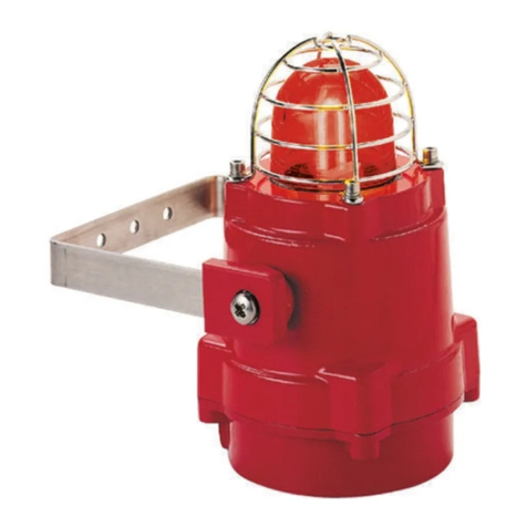
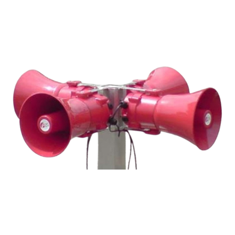
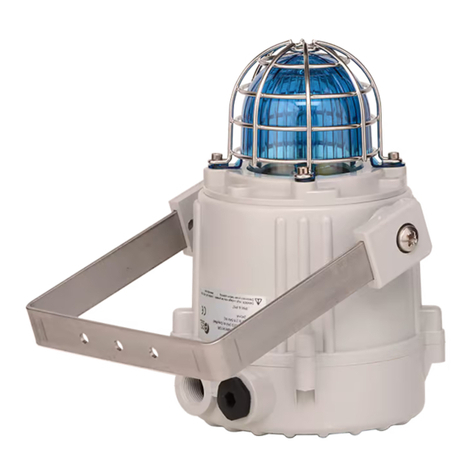
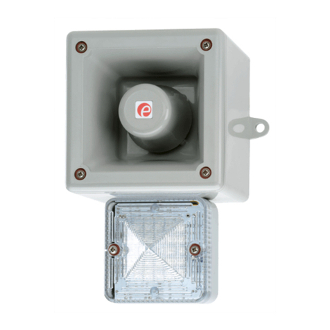
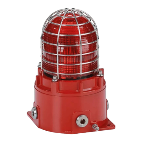
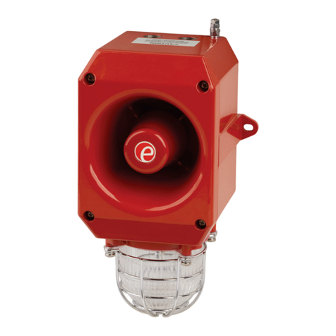
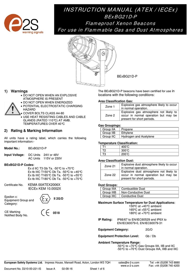
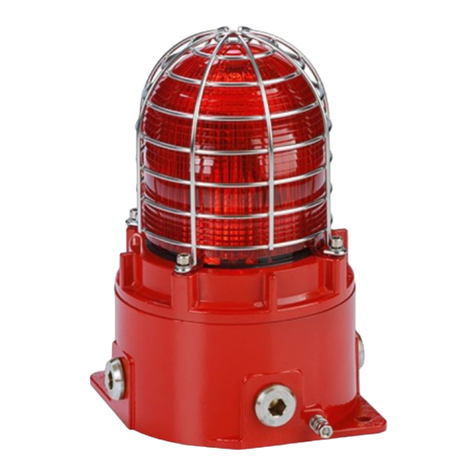
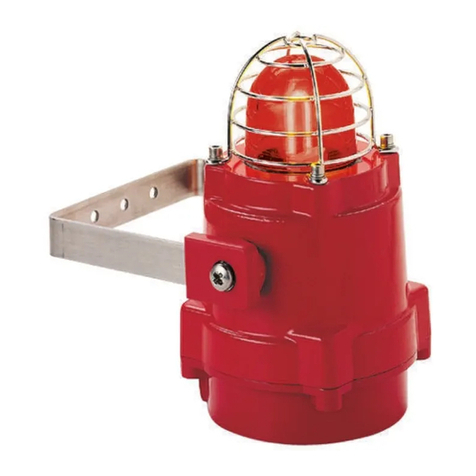
E2S BExCBG05-05D User manual

_______________________________________________________________________________________________________________________________
European SafetySystemsLtd. Impress House, MansellRoad, Acton, London W37QHsales@e-2-s.com Tel: +44 (0)208 743 8880
www.e-2-s.com Fax: +44 (0)208 740 4200
DocumentNo. IS2466 Issue E19-03-10 Sheet1of 5
INSTRUCTIONMANUAL(ATEX/IECEx)
BExCBG05-05D
FlameproofCombined Beacon /Beacon
ForuseinFlammableGas and DustAtmospheres
1)Introduction
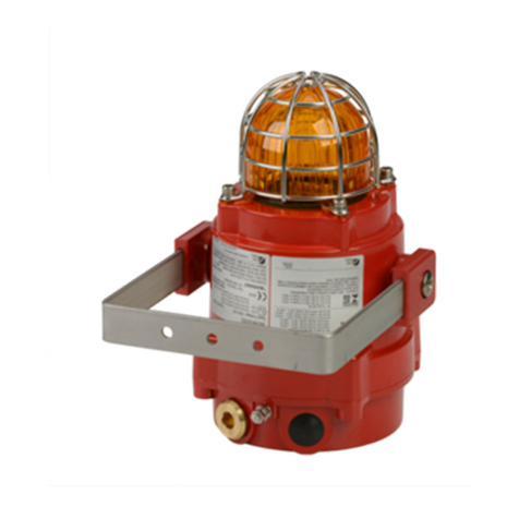
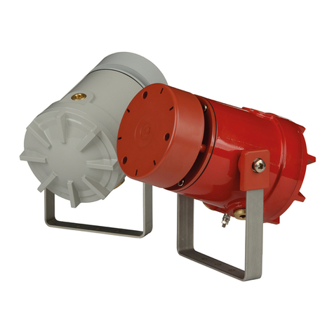
TheBExCBG05-05Disaflameproofcombinedbeacon/
beaconwhichiscertifiedtomeettherequirementsofthe
ATEX directive94/9/EC andtheIECExscheme.Each
beaconsectionproduces asynchronised visualwarning
signalandhasaflashenergyof5joules.Theunit can be
used inhazardousareaswherepotentiallyflammablegas
anddustatmospheres may be present. The unit can be used
inZone1andZone2areaswithgases ingroupsIIAandIIB
andwithTemperatureClassificationsofT1,T2,T3,T4 and
T5 andcan also be usedinZone 21andZone22areasfor
combustibledustsandhavean IPratingofIP67 anda
surface temperatureratingofT115ºC(T100ºCat +55ºC).
2)Marking
All unitshavearatinglabel, whichcarries thefollowing
important information:-
UnitType No. BExCBG050-05D
Input Voltage: DC Units12Vor 24Vor 48V
AC Units230Vor 115V
Codes:
ExdIIBT4 for Ta–50°Cto+70ºC
ExdIIBT5 for Ta–50°Cto+55ºC
ExtDA21IP6XT115°Cbased onmax Taof+70°C
CertificateNo. KEMA01ATEX2222X
IECExKEM10.0024X
“Warnings” DONOTOPENWHENANEXPLOSIVE
GAS / DUSTATMOSPHEREISPESENT
COVERBOLTSCLASS A4-80
USE HEATRESISTINGCABLES AND
CABLEGLANDS (Rated 110ºC) AT
AMB. TEMPERATURES OVER40ºC
Year ofConstruction/
Serial No. i.e. 10 / 1DCB21000001
3) TypeApprovalStandards
TheunitshaveanEC Type examinationcertificateissuedby
KEMAandhavebeenapproved tothefollowingstandards:-
EN60079-0:2006 IEC60079-0:2004(Ed4) General Requirements
EN60079-1:2007 IEC60079-1:2007 (Ed6) Flameproof Enclosure‘d’
EN61241-0:2006 IEC61241-0:2004(Ed1) DustGeneral
Requirements
EN61241-1:2004 IEC60079-1:2004(Ed1) DustEnclosures tD
4) Installation Requirements
Theunit mustbe installed inaccordancewiththelatest
issuesoftherelevantpartsofthe EN60079specifications or
theequivalentIEC specifications–Selection,Installationand
maintenance ofelectricalapparatusforuse inpotentially
explosiveatmospheres(otherthanminingapplicationsor
explosiveprocessingandmanufacture):-
EN60079-14:2008 ElectricalInstallations inHazardous
IEC60079-14:2007 (Ed4)Areas (other than mines)
EN60079-10:2003 Classification of Hazardous Areas
IEC60079-10:2008 (Ed1)
Theinstallationoftheunit mustalso beinaccordance with
any localcodesthatmayapplyandshouldonlybe carried
outbyacompetentelectricalengineerwhohasthe
necessarytraining.
5) Zones,Gas Group, Category,IPRating and
TemperatureClassification
TheBExCBG05-05Dunit hasbeencertifiedExdIIBT4for
Ta–50ºCto+70ºCandExdIIBT5forTa–50ºCto+55ºC
for gas andExtDA21IP6XT100ºC(Ta< +55ºC) or T115ºC
(Ta< +70ºC)fordust. Thismeansthattheunitscan be
installed inlocationswiththefollowingconditions:-
Area Classification Gas:
Zone1Explosivegasairmixturelikelytooccurin
normal operation.
Zone2Explosivegasairmixturenotlikelytooccur,
andifit does, it will onlyexist for ashort time.
GasGroupings:
GroupIIAPropane
GroupIIBEthylene
TemperatureClassification:
T1 400oC
T2 300oC
T3 200oC
T4 135oC
T5 100oC
Area Classification Dust:
Zone21 Explosivedustairmixturelikelytooccurin
normal operation.
Zone22 Explosivedustairmixturenotlikelytooccur,
andifit does, it willonlyexist for ashort time.
0518
CE Marking:
Notified BodyNo.
II 2G/D
Epsilonx:
Equipment Groupand
Category:

_______________________________________________________________________________________________________________________________
European SafetySystemsLtd. Impress House, MansellRoad, Acton, London W37QHsales@e-2-s.com Tel: +44 (0)208 743 8880
www.e-2-s.com Fax: +44 (0)208 740 4200
DocumentNo. IS2466 Issue E19-03-10 Sheet2of 5
IPRating: IP67T100ºCTa< +55ºC
T115ºCTa< +70ºC
Equipment Category: 2G/D
AmbientTemperatureRange: -50°Cto+70°C
6) Location andMounting
Thelocationoftheunit shouldbemadewithdueregardto
theareaoverwhichbothbeaconwarningsignalsmustbe
visible.Theunit shouldonlybefixedtoservicesthatcan
carrytheweight oftheunit.
Theunit shouldbesecurelyboltedtoasuitablesurfaceusing
the7mmdiameterboltholesinthestainlesssteelUshaped
mountingbracket(see figure1). Theanglecan thenbe
adjusted inthedirectionsuchthatitswarningsignalscan be
bothseen.Thiscan be achievedbylooseningthetwolarge
bracketscrewsintheside of theunit, whichallowadjustment
insteps of18°. Oncompletionoftheinstallationthetwolarge
bracketadjustmentscrewsonthe sideoftheunit mustbe
fullytightened toensurethat theunitcannot moveinservice.
SAFETYWARNING:
Theflashdomeguardsmustnotberemovedfromthe
unit at any time.
7) Access to theFlameproofEnclosure
Inordertoconnecttheelectricalsupplycablestothe unit it is
necessarytoremovethecoverbeaconsectiontogain
accesstotheflameproofchamber. To achievethisremove
thefourM6hexagonsocketheadscrews(seefigure2)and
withdrawthecover beaconsectiontakingextremecarenot to
damage theflameproofjointsintheprocess.
Notethefour M6screwsareClass A4-80 stainlesssteel
andonlyscrewsofthiscategorycanbeusedonthese
units. Itisthereforeimportantthatthese screwsandtheir
springwashersarekept inasafeplaceduringinstallation.
Oncompletionofthecablewiringinstallationtheflameproof
jointsshouldbe inspected toensurethattheyareclean and
thattheyhavenotbeendamaged duringinstallation.Also
checkthattheearthbondingwirebetweenthetwocasting
sectionsissecureandthe‘O’ringsealisinplace.When
replacingthebeaconsectioncasting,ensurethatit issquare
withthechamberbeaconsectioncastingbeforeinserting.
Carefullypushthecoverbeaconsectioninplaceallowing
timefortheairtobeexpelled.Onlyafterthecoverbeacon
sectioncastingisfullyinplace shouldthefourM6Stainless
SteelA4-80coverboltsandtheirspringwasherbe inserted
andtightened down.If thecover beaconsectionjamswhileit
isbeing inserted, carefullyremove it andtryagain.Neveruse
thecover boltstoforcethecoverbeaconsectioncastinginto
position.
Incaseof repair, contactthemanufacturerforinformationon
thedimensionsoftheflameproofjoints.
PowerSupplySelection
Itisimportantthatasuitablepowersupplyisusedtorun the
unit. Thepowersupplyselectedmusthavethe necessary
capacitytoprovide theinputcurrenttoall ofthe units
connectedtothesystem.The beaconsectionscan bothbe
wired tothesamepower supplyor todifferent powersupplies
Thefollowingtableshowstheinputcurrenttakenbyeach
beaconsectionofthevariousunits:-
Chamber
Unit TypeInput BeaconMax.
VoltageCurrentI/PVolts
BExCS110-05D24VDC 300mA30V
BExCS110-05D12VDC 750mA15V
BExCS110-05D48VDC 1800mA58V
BExCS110-05D230VAC55mA253V
BExCS110-05D115VAC140mA126V
Cover
Unit TypeInput BeaconMax.
VoltageCurrentI/PVolts
BExCS110-05D24VDC 300mA30V
BExCS110-05D12VDC 750mA15V
BExCS110-05D48VDC 1800mA58V
BExCS110-05D230VAC55mA253V
BExCS110-05D115VAC140mA126V
Theabovetablealsoshowsthe maximumvoltagesatwhich
theunitscan be operated.
Thecircuitsofeachbeaconsectionarethesame.The input
currenttoeachbeaconsectionwill varyaccordingtothe
voltage inputlevel. Thecurrentlevelsshownabovearefor
nominalinputvoltage.The12V,24Vand48VDC unitshave
aconvertercircuit andthereforetheinputcurrentlevelwill
S/SMounting
Bracket
Flashdome
Guard
Fig1
ChamberBeac
on
Section
CoverBeacon
Section
Flashdome
Guard
4off Cover Screws
ExternalEarth
Terminal
Fig2

_______________________________________________________________________________________________________________________________
European SafetySystemsLtd. Impress House, MansellRoad, Acton, London W37QHsales@e-2-s.com Tel: +44 (0)208 743 8880
www.e-2-s.com Fax: +44 (0)208 740 4200
DocumentNo. IS2466 Issue E19-03-10 Sheet3of 5
decreaseslightlyastheinputvoltageinincreasedandwill
increase slightlyastheinput voltage isreduced.
8) CableSelection
Whenselectingthecablesizeconsiderationmustbegivento
theinputcurrentthateachunit draws(see tableabove), the
numberofunitsonthelineandthelengthofthecableruns.
Thecablesizeselectedmusthavethenecessarycapacityto
provide theinputcurrenttoall oftheunitsconnectedtothe
line.
SAFETYWARNING: Iftheunit isusedathighambient
temperatures,i.e.over+40ºC,thenthecableentry
temperaturemay exceed +70ºCandthereforesuitableheat
resistingcables mustbeused,witharated service
temperatureofat least 110ºC.
9) Earthing
BothAC andDC unitsmustbeconnectedtoagood quality
earth.Theunitsareprovidedwithinternalandexternal
earthingterminals,whichareboth,locatedonthe beacon
sectionoftheunit (see figures2and3).
Whenusingtheinternalearthterminalensurethatthe
stainless steelM4flatwasherisbetweentheincoming earth
wireandtheenclosure.
Whenusingtheexternalearthterminalacablecrimplug
mustbe used.Thecablelugshouldbe locatedbetweenthe
twoM5stainless steelflatwashers.TheM5stainlesssteel
springwashermustbe fixed betweentheouterflatwasher
andtheM5stainless steelnuttoensurethatthecablelugis
secured against looseningandtwisting.
Theinternalearthbondingwireensuresthatagoodquality
earthismaintained betweenthesoundersectioncastingand
thebeaconsectioncasting.
10) CableGlands
TheBExCBG05-05Dunit hasdualcableglandentrieswhich
haveanM20 x1.5entrythreadasstandardoraPG13.5
threadasaspecial. Onlycableglands approvedforEx‘d’
applicationscan be used,whichmustbesuitableforthetype
ofcablebeingusedandalso meet therequirementsoftheEx
‘d’flameproofinstallationstandardEN60079-14:2008 /
IEC60079-14:2007.
Whenonlyonecableentryisusedtheotheronemustbe
closedwithanEx‘d’ flameproofblankingplug, whichmust be
suitablyapproved for theinstallationrequirements.
For combustibledustapplications,thecableentrydevice and
blankingelementsshall be intype ofexplosionprotection
increasedsafety"e"orflameproofenclosure"d"andshall
haveanIP6XratingaccordingtoEN60529:1992
SAFETYWARNING: Iftheunit isusedathighambient
temperatures,i.e.over+40ºC,thenthecableentry
temperaturemay exceed +70ºCandthereforesuitableheat
resistingcableglandsmustbe used,witharated service
temperatureofat least 110ºC.
11) CableConnections
Thecombinedbeacon/beaconunitBExCBG05-05Dhas
separateprinted circuit boardsforeachbeaconsection.The
terminalsforthechamberbeaconareontheprinted circuit
boardinthechamberbeaconsectionandtheterminalsfor
thecoverbeaconareontheprintedcircuit boardinthecover
beaconsection(seefigures 4&5and6&7). Seesection7of
thismanualforaccesstotheenclosureandthewiring
diagramsat theendofthismanual.
Bothbeaconsectionscan be wired tothesameinputsupply
so thattheyoperatesimultaneouslyortheycanbe wired to
separateinputsupplies sotheycan be operated
independently(seediagramsofpages 4and5ofthis
manual). If thebeaconsectionsareconnected tothesame
inputsupply,theincoming cablesshouldbeconnectedtothe
inputterminalsonthecoverbeaconboardandthetwo
connectingwires,thataresuppliedwiththeunit,shouldbe
usedtolink thesupplyfromtheinterconnecting terminalson
thecoverbeaconboarddowntothesupplyterminalsonthe
chamber beaconboard.
CHAMBER BEACONSECTIONCONECTIONS
Thecableconnectionsaremade intotheterminalblockson
theelectronicpcbassemblylocatedinthechamberbeacon
sectionenclosure.Afour-wayterminalblockisprovidedon
bothACandDCbeacons.Thereforetherearetwolive
terminalsandtwoneutralterminalsfortheinputandoutput
wiringonAC units.OntheDC unitstherearetwo+ve
terminalsandtwo-veterminalsfortheinputandoutput
wiring. (see figure6).
Wireshavingacross sectionalarea ofupto4mm²can be
connected toeachterminalway.Whenconnectingwires to
theterminalsgreatcareshouldbe takentodressthewireso
thatwhenthecoverbeaconsectionisinsertedintothe
chamberthewires do notexert excesspressureonthe
terminalblocks.Thisisparticularlyimportantwhenusing
cableswithlarge crosssectionalareassuchas2.5mm²and
above.Ifbothbeaconsarewired tothesamepowersupply
alwaysuse theflexibleinterconnectingwires provided.
COVER BEACONSECTIONCONNECTIONS
Thecableconnectionsaremade intotheterminalblockson
theelectronicpcbassemblylocatedinthecoverbeacon
sectionenclosure.Afour-wayterminalblockisprovidedon
bothACandDCbeacons.Thereforetherearetwolive
terminalsandtwoneutralterminalsfortheinputandoutput
wiringonAC units.OntheDC unitstherearetwo+ve
InternalBonding Wire Terminal
InternalEarthTerminal
2off M20
CableEntries
Figure3

_______________________________________________________________________________________________________________________________
European SafetySystemsLtd. Impress House, MansellRoad, Acton, London W37QHsales@e-2-s.com Tel: +44 (0)208 743 8880
www.e-2-s.com Fax: +44 (0)208 740 4200
DocumentNo. IS2466 Issue E19-03-10 Sheet4of 5
Cover
Beacon
PCB
Chamber
Beacon
PCB
Chamber
Beacon
PCB
Unit No. 1 Unit No.2UnitNo. 3
Cover
Beacon
PCB
Chamber
Beacon
PCB
Cover
Beacon
PCB
+
-
+
-
+
-+-+- +-+-
+-
+-
-
+
terminalsandtwo-veterminalsfortheinputandoutput
wiring.
Wireshavingacross sectionalarea ofupto4mm²can be
connected toeachterminalway.Whenconnectingwires to
theterminalsgreat careshouldbe takentodress thewires so
thatwires do notexert excesspressureontheterminal
blocks.Thisisparticularlyimportantwhenusingcables with
large cross sectional areassuchas2.5mm² andabove.
12) End ofLineMonitoring (DC Units)
OnBExCBG05-05DDC units,dc reverse linemonitoringcan
beusedifrequired.All DC unitshaveablockingdiodefitted
intheirsupplyinputlines onbothbeaconsections.Anendof
linemonitoringdiode oran end of line monitoringresistor can
be connected across the+veand–veterminals.If anendof
lineresistorisused it musthaveaminimumresistance value
of3k3ohmsandaminimumwattage of0.5wattsora
minimumresistance valueof500ohmsandamin.wattage of
2watts.If thebeaconsectionsarewired toseparatepower
suppliesthenan endofline monitoringcomponentcan be
used ineachsection.
13) Synchronised Operation
All BExCBG05-05Dunitsthatareconnectedtothesame
supplylinewill haveasynchronised flashrateatoneflash
everysecond.Toensurethattheunitswill be synchronised
checkthat thepinheader isnot fitted, i.e. thetwoheader pins
arenot shorted together (see Figures 4and5).
14) Flip / Flop Operation
Thetwobeaconsectionscan be settoformaflip-flop
operation,wherethebeaconswill flashalternately.To
achievethismodeofoperation,fit apinheadertotheflip-
flopheaderpinsononeoftheelectronicsboard,i.e.thetwo
headerpinsareshortedtogether, (seefigures 4to6). The
firstflashonthebeaconthathastheheaderfitted will be
delayed by½second.Thetwobeaconswill thenflash
alternatelyevery½asecond.
L
L
N
N
Figure4
ACInput
Terminals
BExCBG05
-
05DAC Cover BeaconSection
BExCBG05
-
05DDCCover BeaconSection
DC Input
Terminals
Figure5
-
-
+
+
Flip / Flop
Pin Header
Flip / Flop
Pin Header
BExCBG05-05DChamber BeaconSection
Supply
Terminals
Figure6
Flip / Flop
Pin Header
Interconnecting Terminalsto
chamberbeacon pcb(simultaneousor
flip flop mode of operation)
Interconnecting Terminalsto
chamberbeacon pcb(simultaneousor
flip flop mode of operation)
BExCBG05
-
05DDCCombinedBeaconUnit
Beacons Wired for Simultaneous(or ifthe header link isinplace
on one of the pcb’s) FlipFlop Operation (see sections14 and 15)

_______________________________________________________________________________________________________________________________
European SafetySystemsLtd. Impress House, MansellRoad, Acton, London W37QHsales@e-2-s.com Tel: +44 (0)208 743 8880
www.e-2-s.com Fax: +44 (0)208 740 4200
DocumentNo. IS2466 Issue E19-03-10 Sheet5of 5
Cover
Beacon
PCB
+
-
+
-
+-
Chamber
Beacon
PCB
+-
UnitNo.1
Chamber
Beacon
PCB
Cover
Beacon
PCB
+-
Chamber
Beacon
PCB
+-
Cover
Beacon
PCB
+-+-
UnitNo. 2UnitNo.3
L
N
L
N
L
NLN
LN
LN
LN
LNLN
Cover
Beacon
PCB
Chamber
Beacon
PCB
Cover
Beacon
PCB
Chamber
Beacon
PCB
Cover
Beacon
PCB
Chamber
Beacon
PCB
UnitNo.3
UnitNo.2
UnitNo.1
L
N
L
L
N
N
Cover
Beacon
PCB
LN
Chamber
Beacon
PCB
LNLN
Cover
Beacon
PCB
Chamber
Beacon
PCB
LN
Cover
Beacon
PCB
LN
Chamber
Beacon
PCB
LN
Unit No.3
UnitNo.2
UnitNo.1
BExCBG05
-
05DDCCombinedBeaconUnit
BeaconsWiredfor Independent Operation
BExCBG05
-
05DACCombinedBeaconUnit
Beacons Wired for Simultaneous(or ifthe header link isinplace
on one of the pcb’s) FlipFlop Operation (see sections14 and 15)
BExCBG05
-
05DACCombinedBeaconUnit
BeaconsWiredfor Independent Operation
NOTE
Eitherthe+veorthe-vewiremay
bemadecommontoboththe
chamberand coverbeaconsto
reducethenumberof coresinthe
cable.
NOTE
EithertheLortheNwiremaybe
madecommontoboththesounder
and thebeacontoreducethe
numberof coresinthecable.
Table of contents
Other E2S Security System manuals

E2S
E2S D1xB2X Series User manual

E2S
E2S STExB2X05DC012 User manual

E2S
E2S BexCS11005D24DC-RD User manual

E2S
E2S A131 User manual

E2S
E2S GNExCP7-BG-S User manual

E2S
E2S BExBG05 Series User manual

E2S
E2S D1xC3 User manual

E2S
E2S BExCBL2-L2D-P User manual

E2S
E2S SONFL1H-HO Series User manual

E2S
E2S STExB2LD2 User manual