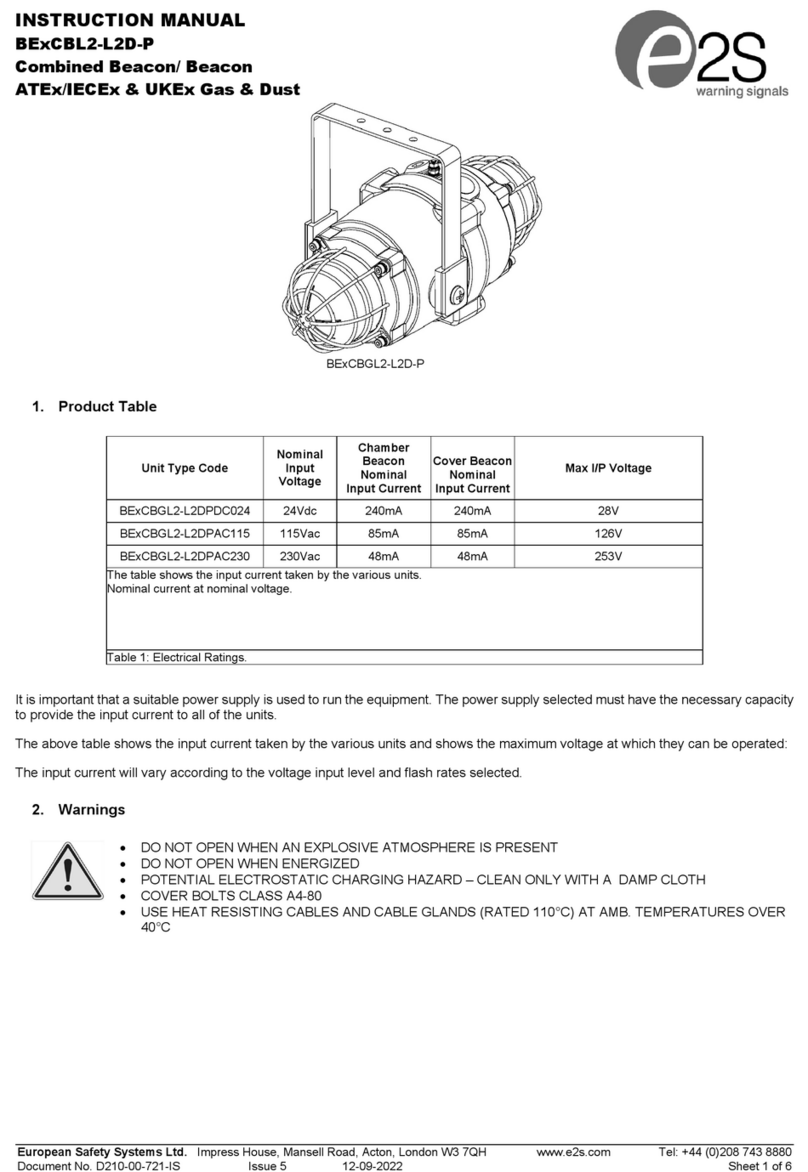
manuals.online logo
Brands
  1. Home
  2. •
  3. Brands
  4. •
  5. E2S
  6. •
  7. Security System
  8. •
  9. E2S SONFL1XDC012 User manual

E2S SONFL1XDC012 User manual


E2S Warning Signals Impress House, Mansell Road, Acton, London W3 7QH [email protected] e2s.com Page 1 of 3 D242-00-511-IS_Issue_1 - 26/04/2021
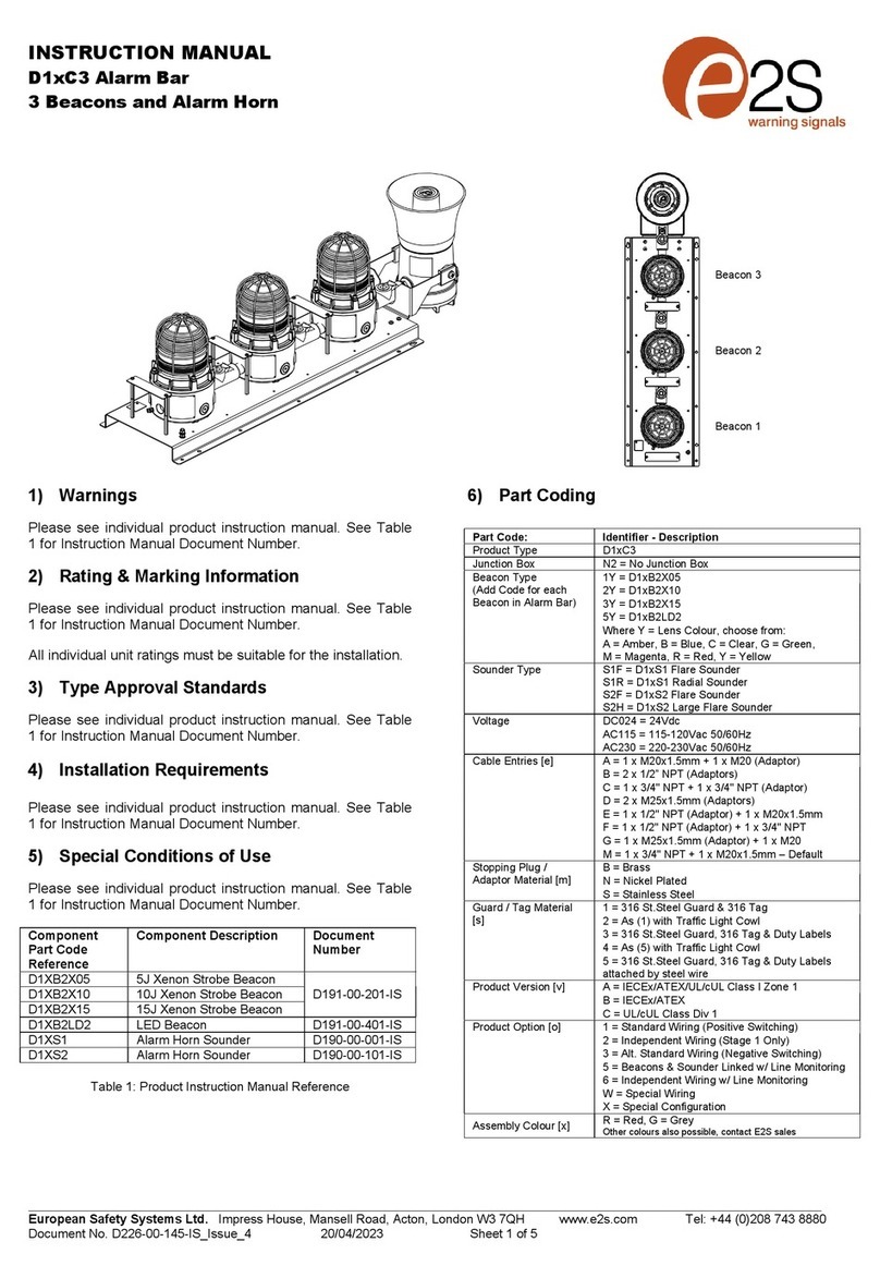
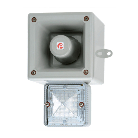
INSTRUCTION & SERVICE MANUAL
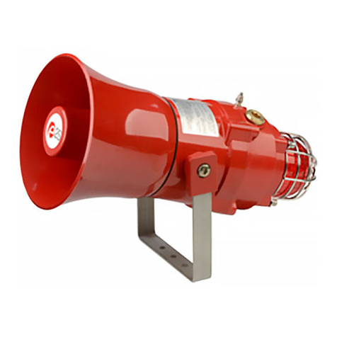
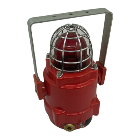
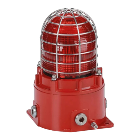
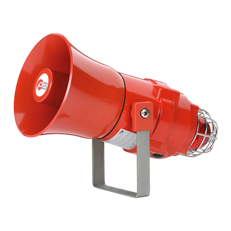
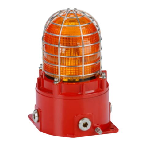
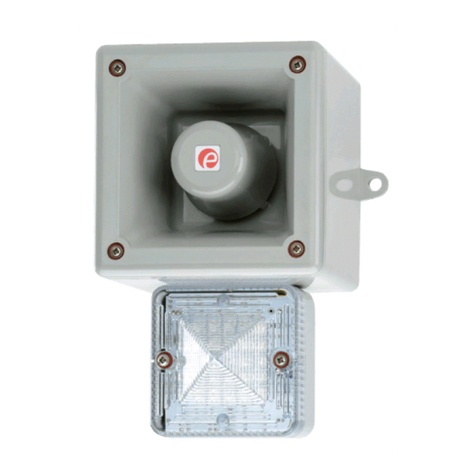
SONFL1X-HO Range - High Output Alarm Horn & Xenon Strobe Beacon






+ve IN
-ve IN
+
+
-
-
Stage 2 S2
-
+
-
+
DC
Dimensions: 172 x 86 x 83mm
Cable Entry: 2-off M20 x 1.5mm
Temp: -40°C to +55°C
Unit weight: 0.46Kg
Model No. Nominal Voltage Voltage Range Horn Nom.
Current
Beacon Nom.
Current
Sound Pressure Level dB(A)
Max Nominal
SONFL1XDC012…[X]/[Y]-H 12V dc 10-14V dc 50mA 500mA 105.0 @ 1m
96.0 @ 3m
103.0 @ 1m
94.0 @ 3m
SONFL1XDC024…[X]/[Y]-H 24V dc 20-28V dc 80mA* 250mA
*Current at nominal voltage on Tone 2
[X] Denotes Housing Colour: R = Red; G = Grey; W = White
[Y] Denotes Lens Colour: A = Amber; B = Blue; C = Clear; G = Green; M = Magenta; R = Red; Y = Yellow
Note: CPR Approved Units only available with Clear Lens
SONFL1X-HO Combined Sounder & Xenon Beacon
10 Selectable Tones & 2 Stages
5J Xenon Flash Tube
Three Modes: Flashing 1Hz (AC & DC)
Flashing 1.5Hz and Double Strike (DC Units Only)
1Hz Flashing mode CPR / VdS approved
24Vdc version CPR / VdS approved
CE, EAC Approved
IP Rating: IP66
Use suitable conduit or cable glands with
suitable IP or type rating 0.4Nm
5
0.5 - 1.5mm²
Terminal Connections
SONFL1X-HO
Attention: Installation must be carried out by an electrician in compliance with the latest codes and regulations.
Attention: L'installation doit être effectuée par un électricien conformément aux derniers codes et réglementations.
Achtung: Die Installation muss von einem Elektriker gemäß den neuesten Vorschriften und Bestimmungen durchgeführt werden.
Attenzione: L'installazione deve essere eseguita da un elettricista in conformità con i codici e le normative più recenti.
Atención: La instalación debe ser realizada por un electricista de acuerdo con los últimos códigos y regulaciones.
Atenção: A instalação deve ser realizada por um eletricista de acordo com os códigos e regulamentos mais recentes.
Внимание: установка должна выполняться электриком в соответствии с последними нормами и правилами.
Attention: Disconnect from power source before installation or service to prevent electric shock
Attention: Débranchez-le de la source d'alimentation avant l'installation ou l'entretien pour éviter tout choc électrique.
Achtung: Vor Installation oder Wartung von der Stromquelle trennen, um einen Stromschlag zu vermeiden.
Attenzione: scollegare dall'alimentazione prima dell'installazione o dell'assistenza per evitare scosse elettriche.
Atención: desconéctelo de la fuente de alimentación antes de la instalación o el servicio para evitar descargas eléctricas.
Atenção: Desconecte da fonte de alimentação antes da instalação ou serviço para evitar choque elétrico
Внимание: отключите от источника питания перед установкой или обслуживанием, чтобы предотвратить поражение
электрическим током.
Noliabilityisacceptedforanyconsequencesoftheuseofthisdocument.Thetechnicalspecificaonofthisunitissubjecttochangewithoutnoceduetoourpolicyofconnual
productdevelopment.Alldimensions/weightsareapproximate.Thisunitissoldsubjecttoourstandardcondionsofsale,acopyofwhichisavailableonrequest.
DC Circuit
See D242-06-501 - Schematic Wiring
S2
SWITCH
+-
Volume
Control
Tone Selection
(See Table)
S2 Denotes Stage 2
customer supplied
Stage switches are
BEACON
PCBA
+
-
Stage 1: Apply Power to +ve & -ve
Stage 2: Apply Power to +ve & -ve & connect Stage 2 to -ve
Beacon pre-wired to Alarm terminals by default
Note: Stage 2 is not VdS Approved

E2S Warning Signals Impress House, Mansell Road, Acton, London W3 7QH [email protected] e2s.com Page 2 of 3 D242-00-511-IS_Issue_1 - 26/04/2021
INSTRUCTION & SERVICE MANUAL
SONFL1X-HO Range - High Output Alarm Horn & Xenon Strobe Beacon




800/1000 Hz @ 0.25 sec Alternating BS5839 Alarm Tone
500/1200 Hz @ 0.3 Hz 0.5 sec Slow Whoop NEN 2575:2000
544Hz (100mS)/440 Hz (400mS) AFNOR NF S 32-001
Simulated Bell Sound
Sweeping 800/1000 Hz @ 7 Hz Sweeping
500-1200 Hz 3.75 sec / 0.25 sec Australian Evacuation
Continuous 1000 Hz - PFEER toxic gas
Continuous 554 Hz
420 Hz @ 0.625 sec Australian Alert
1
2
3
4
5
6
7
8
9
Sawtooth 1200/500 Hz @ 1 Hz - DIN / PFEER P.T.A.P
10
8
8
8
1
1
9
10
Tone DescriptionStage 1 Stage 2
-
-
-
99dB(A) @1m
100dB(A) @1m
99dB(A) @1m
97dB(A) @1m
95dB(A) @1m
99dB(A) @1m
100dB(A) @1m
100dB(A) @1m
97dB(A) @1m
97dB(A) @1m
SONF1 dB@ 1m
12V DC and 24V DC Tone Table
NOTE: Please check factory settings and ensure the correct alarm tone is selected for your country or application
Tone Selection / Header Pin Setting - Header pin settings are shown in the tone selection table. The links covered by the jumper are
shown with a black rectangle.
Only tones 1, 2, 3, 4, 8 & 9 (DC) have been tested to EN54-3 and are compliant with the Construction Products Regulation 305/2011.
Header Pin settings
for flashing modes.
A
B
C
A
B
C
A
B
C
A
B
C
1Hz Flash (60FPM)
1.5Hz Flash (90FPM)
Double Strike Flash Pattern
Torque 5Nm
Disassembly Reassembly
Beacon Flash Settings
Mounting See D242-05-501
Attention: On strobe beacons allow a minimum of 2
minutes for hazardous high voltage to discharge
from unit
Loosen posi-pan screws
in four positions to
access enclosure
Access to Enclosure
98,0 [3,86]
Ø6.3 [0.25]
Cabl e Ent ry
Ø20.5mm [0.81"]
Rear Ø20mm Knockout
for M20 Cable Entry
if required
Pilot drilling positions
for internal mounting
holes if required
Adhere supplied
Gaskets to
backboxes to
maintain IP rating
DC
Tone
Settings
Tone 1
Tone 2
Tone 3
Tone 4
Tone 5
Tone 6
Tone 7
Tone 8*
Tone 9*
Tone 10*
*To set tones 8, 9 & 10 as first stage on DC, connect terminal ‘S2’ to ‘-’ terminal

E2S Warning Signals Impress House, Mansell Road, Acton, London W3 7QH [email protected] e2s.com Page 3 of 3 D242-00-511-IS_Issue_1 - 26/04/2021
INSTRUCTION & SERVICE MANUAL
SONFL1X-HO Range - High Output Alarm Horn & Xenon Strobe Beacon
Power
7W
V=55.3m³
Category W-x-y (Wall mounted):
Wall mounted, where x is the maximum
mounting height from the floor and y is the
maximum length of the sides of the square
floor area covered by the VAD.
y
y
x
W-2.4-4.8
Unit Category W
SONFL1XDC024...[X]/C-H
Coverage Area According to EN54-23
(Only units in the following
table are VdS Approved)
Note: CPR aproved units must be
positioned sounder on top, beacon
below.




SONFL1XDC024-H HORIZONTAL POLAR PLOT SONFL1XDC024-H VERTICAL POLAR PLOT
SONFL1XDC024-H SOUND PRESSURE LEVEL OUTPUT
(TESTING AT MINIMUM VOLTAGE OF 18V DC. ALL READINGS ARE IN dB(A) @ 1m)
SONFL1XDC024-H LIGHT OUTPUT

This manual suits for next models

7

Other E2S Security System manuals

E2S D2 C2X05DC024 Series User manual

E2S

E2S D2 C2X05DC024 Series User manual

E2S BExBG05D User manual

E2S

E2S BExBG05D User manual

E2S D1xC2 Series User manual

E2S

E2S D1xC2 Series User manual

E2S AlertAlight DL105X User manual

E2S

E2S AlertAlight DL105X User manual

E2S BExCBL2-L2D-P User manual

E2S

E2S BExCBL2-L2D-P User manual

E2S STExB2RT1 User manual

E2S

E2S STExB2RT1 User manual

E2S D1xB2X Series User manual

E2S

E2S D1xB2X Series User manual

E2S GNExB2X05-S Series User manual

E2S

E2S GNExB2X05-S Series User manual

E2S GNExB2LD2 User manual

E2S

E2S GNExB2LD2 User manual

E2S BExBG21D-P User manual

E2S

E2S BExBG21D-P User manual

E2S STExS2 User manual

E2S

E2S STExS2 User manual

E2S BExCTS110-05D-P User manual

E2S

E2S BExCTS110-05D-P User manual

E2S GNExCP6C-PB User manual

E2S

E2S GNExCP6C-PB User manual

E2S E2xC1LD2R User manual

E2S

E2S E2xC1LD2R User manual

E2S D1xS2 Series User manual

E2S

E2S D1xS2 Series User manual

E2S D2xC1 Troubleshooting guide

E2S

E2S D2xC1 Troubleshooting guide

E2S SONFL1H-HO Series User manual

E2S

E2S SONFL1H-HO Series User manual

E2S D2XC2XH1 User manual

E2S

E2S D2XC2XH1 User manual

E2S GNExCP6C-PT User manual

E2S

E2S GNExCP6C-PT User manual

E2S Appello A121APPX User manual

E2S

E2S Appello A121APPX User manual

E2S HA121 User manual

E2S

E2S HA121 User manual

E2S D1xB2LD2 Series User manual

E2S

E2S D1xB2LD2 Series User manual

E2S IS-CP4B-PT User manual

E2S

E2S IS-CP4B-PT User manual

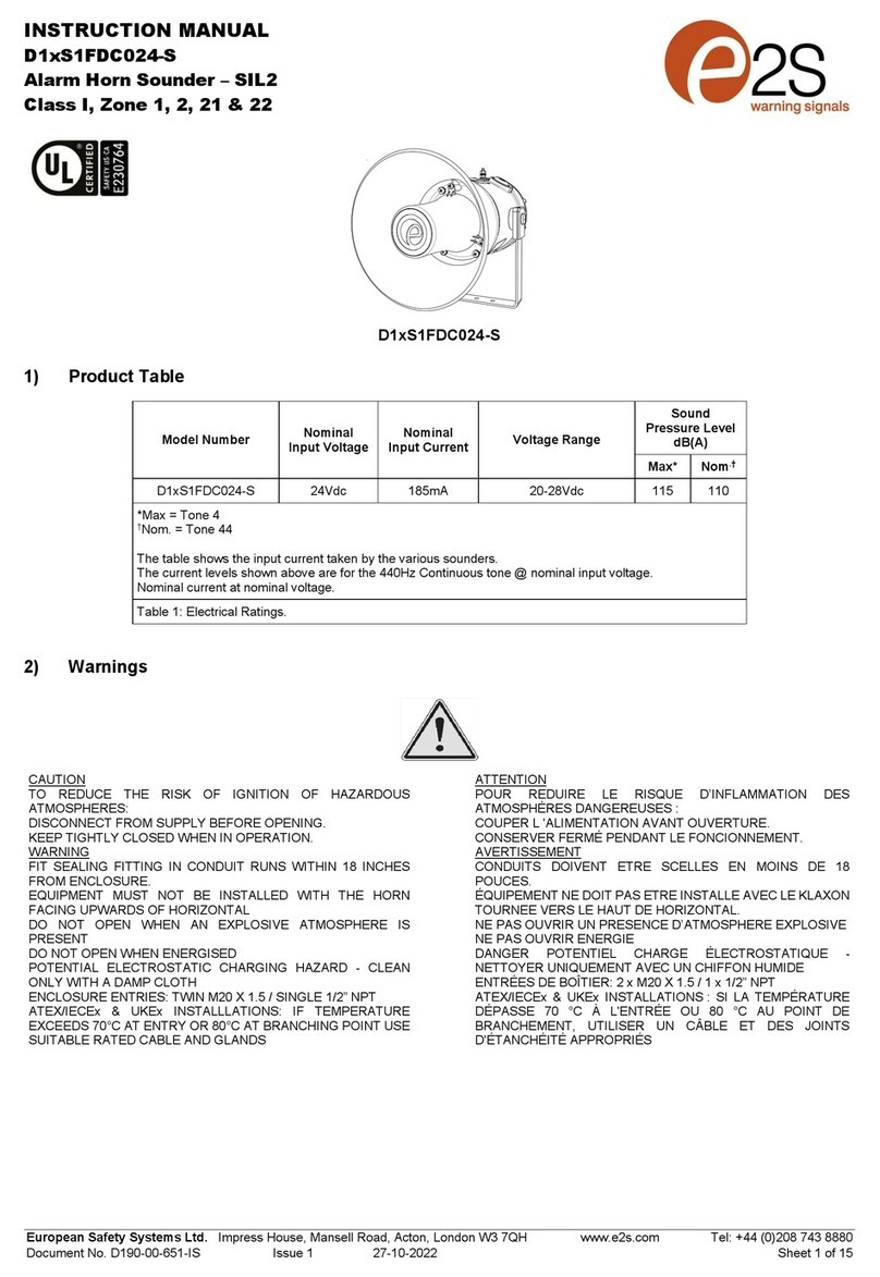
E2S D1xS1FDC024-S User manual

E2S

E2S D1xS1FDC024-S User manual

Popular Security System manuals by other brands

GE Interlogix CareGard 60-883-95R installation instructions

GE Interlogix

GE Interlogix CareGard 60-883-95R installation instructions

SECO-LARM Enforcer SD-7103GC-PEQ installation manual

SECO-LARM

SECO-LARM Enforcer SD-7103GC-PEQ installation manual

Hiltron security XR500 user manual

Hiltron security

Hiltron security XR500 user manual

LogicMark notifi911+ User's quick start guide

LogicMark

LogicMark notifi911+ User's quick start guide

Idappcom GIPSY quick start guide

Idappcom

Idappcom GIPSY quick start guide

Sony SRG-300SE Technical manual

Sony

Sony SRG-300SE Technical manual

AV-CAD AV-5000 LED Installation and operation manual

AV-CAD

AV-CAD AV-5000 LED Installation and operation manual

Sting HD-104 user manual

Sting

Sting HD-104 user manual

IDS 400 user manual

IDS

IDS 400 user manual

Lorex Vantage Edge+ CVC6996 Brochure & specs

Lorex

Lorex Vantage Edge+ CVC6996 Brochure & specs

Riken Keiki RM-5000 Series User Manual for Communication

Riken Keiki

Riken Keiki RM-5000 Series User Manual for Communication

LEGRAND 4073 quick start guide

LEGRAND

LEGRAND 4073 quick start guide

Britax BF920 Series Installation & operation manual

Britax

Britax BF920 Series Installation & operation manual

DEXAPLAN WA 620 manual

DEXAPLAN

DEXAPLAN WA 620 manual

ALC SecuFirst ALM314S quick start guide

ALC

ALC SecuFirst ALM314S quick start guide

Huato S210 Operation manual

Huato

Huato S210 Operation manual

ADEMCO VISTA user manual

ADEMCO

ADEMCO VISTA user manual

SVAT CLEARVU11 Specifications

SVAT

SVAT CLEARVU11 Specifications

manuals.online logo
manuals.online logoBrands
  • About & Mission
  • Contact us
  • Privacy Policy
  • Terms and Conditions

Copyright 2025 Manuals.Online. All Rights Reserved.