_______________________________________________________________________________________________________________________________
European
Safety
Syst
ems
Ltd.
Impress House, Mansell Road, Acton, London W3 7QH [email protected] Tel: +44 (0)208 743 8880 www.e2s.com Fax: +44 (0)208 740 4200
Document No. D211-00-251-IS-SC Issue F 02-03-2020 Sheet 2 of 9
2.5 ATEX / IECEx certification
The D2xB1XH1 and D2xB1XH2 xenon beacons comply with
the following standards:
EN60079-0:2012+A11:2013 / IEC60079-0: ed. 6.0 (2011-06)
EN60079-15:2010 / IEC60079-15: ed. 4.0 (2010-01)
EN60079-31:2014 / IEC60079-31:2013 ed. 2.0 (2013-11)
Certificate No. DEMKO 14 ATEX 4786493904X
IECEx ULD 14.0004X
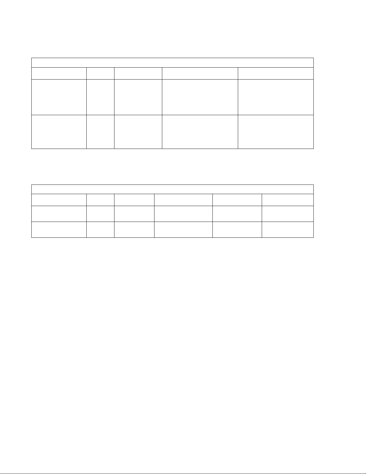
The D2xB1XH1 Xenon Beacon is rated as follows:
The D2xB1XH2 Xenon Beacon is rated as follows:
CE Marking
Zones, Gas / Dust Groups and Temperature
Classification
When connected to an approved system the D2xB1XH1 and
D2xB1XH2 xenon beacons may be installed in:
Zone 2 explosive gas air mixture not likely to occur
in normal operation, and if it does, it will only exist
for a short time.
Zone 22 explosive dust air mixture not likely to occur
in normal operation, and if it does, it will only exist
for a short time.
May be used with gases in groups:
Group IIA propane
Group IIB ethylene
Group IIC hydrogen / acetylene
Having a temperature classification
(for Gas applications) of:
T1 450ºC
T2 300ºC
T3 200ºC (D2xB1XH1 only)
May be used with Dust types:
Group IIIA combustible flyings
Group IIIB non-conductive dust
Group IIIC conductive dust
Maximum Surface Temperature for Dust Applications:
XH1 80°C & XH2 105°C
Installation must be carried out in compliance with the latest
issue of the following standards:
EN60079-14 / IEC60079-14: Explosive atmospheres -
Electrical installations design, selection and erection
EN60079-10-1 / IEC60079-10-1: Explosive atmospheres -
Classification of areas. Explosive gas atmospheres
EN60079-10-2 / IEC60079-10-2: Explosive atmospheres –
Classification of areas. Explosive dust atmospheres
2.6 Ingress Protection Ratings
The product is rated for ingress Protection as follows:
IP rating: IP66
Type rating per UL50E / NEMA250: 4 / 4X / 3R / 13
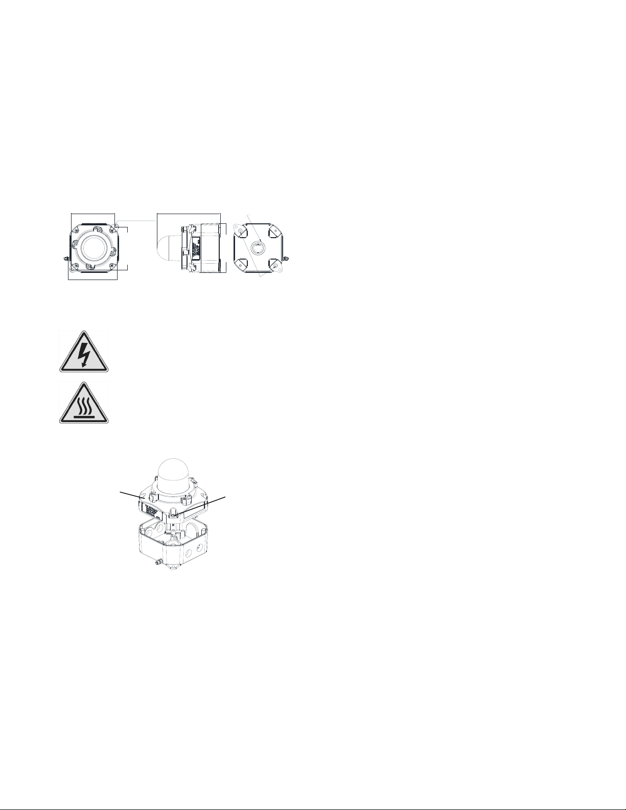
To maintain the ingress protection rating, the two off cable
entries must be fitted with suitably rated, certified cable entry
and/or blanking devices during installation.
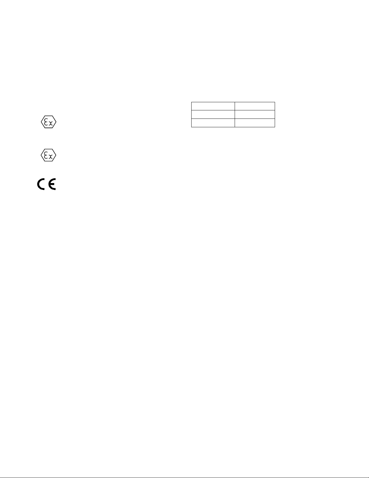
2.7 Electrical Ratings
Model No. Voltage Range
D2xB1XH1 20-28Vdc
D2xB1XH2 20-28Vdc
Table 1: Electrical Ratings
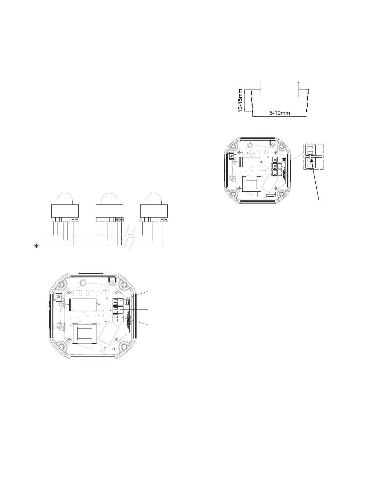
It is important that a suitable power supply is used to run the
equipment. The power supply selected must have the
necessary capacity to provide the input current to all the
units.
The input current will vary according to the voltage input
level.
For detailed max and surge current ratings of the device
please see Section 13.
3) Special Conditions of Use
Special Condition for safe Use as stated on the Type
Examination Certificate DEMKO 14 ATEX 4786493904X /
CoC IECEx ULD 14.0004X:
When used for a Group III application, the surface of the
enclosure may store electrostatic charge and become a
source of ignition in applications with a low relative humidity
<~30% relative humidity where the surface is relatively free of
surface contamination such as dirt, dust, or oil.
Guidance on protection against the risk of ignition due to
electrostatic discharge can be found in EN TR50404 and IEC
TR60079-32.
End user shall adhere to the manufacturer’s installation and
instruction when performing housekeeping to avoid the
potential for hazardous electrostatic charges during cleaning,
by using a damp cloth.
To maintain the ingress protection rating and mode of
protection, the cable entries must be fitted with suitably rated,
certified cable entry and/or blanking devices during
installation. If conduit is used for installation, seal conduit
within 18 inches from the enclosure.
2813
II 3G Ex nA IIC T2 Gc Ta -40°C to +50°C
II 3D Ex tc IIIC 80°C Dc Ta -40°C to +50°C
II 3G Ex nA IIC T1 Gc Ta -40°C to +50°C
II 3D Ex tc IIIC 105°C Dc Ta -40°C to +50°C