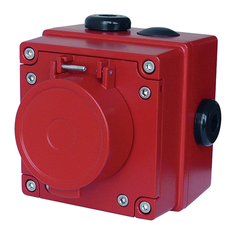
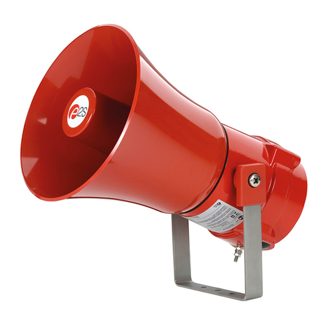
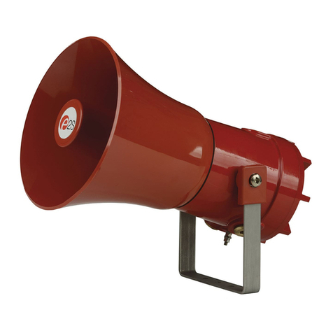
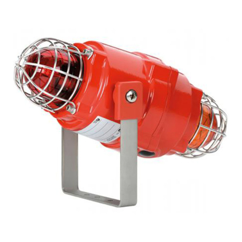
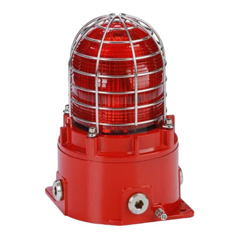
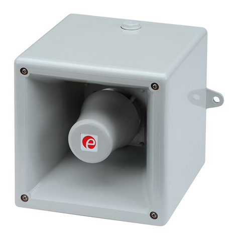
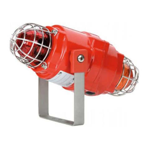
E2S D1xC3 User manual

INSTRUCTION MANUAL
D1xC3 Alarm Bar
Beacon and Alarm Horn
_______________________________________________________________________________________________________________________________
European Safety Systems Ltd. Impress House, Mansell Road, Acton, London W3 7QH www.e2s.com Tel: +44 (0)208 743 8880
Document No. D226-00-125-IS_Issue_4 20/04/2023 Sheet 1 of 5
1) Warnings
Please see individual product instruction manual. See Table
1 for Instruction Manual Document Number.
2) Rating & Marking Information
Please see individual product instruction manual. See Table
1 for Instruction Manual Document Number.
All individual unit ratings must be suitable for the installation.
3) Type Approval Standards
Please see individual product instruction manual. See Table
1 for Instruction Manual Document Number.
4) Installation Requirements
Please see individual product instruction manual. See Table
1 for Instruction Manual Document Number.
5) Special Conditions of Use
Please see individual product instruction manual. See Table
1 for Instruction Manual Document Number.
Table 1: Product Instruction Manual Reference
6) Part Coding
Component
Part Code
Reference
Component Description Document
Number
D
1
XB2X05
5J Xenon Strobe Beacon
D191-00-201-IS
D
1
XB2X
10
10J Xenon Strobe Beacon
D1XB2X15
15J Xenon Strobe Beacon
D
1
XB2
LD2
LED Beacon
D
191
-
00
-
401
-
IS
D1XS1
Alarm Horn Sounder
D190
-
00
-
001
-
IS
D1
X
S2
Alarm
Horn Sounder
D190
-
00
-
1
01
-
IS
Part Code:
Identifier
-
Description
Produc
t Type
D
1
x
C3
Junction Box
N
2
=
No Junction Box
Beacon Type
(Add Code for each
Beacon in Alarm Bar)
1
Y
= D
1
x
B
2
X
05
2Y = D1xB2X10
3
Y
= D1
x
B
2
X
1
5
5
Y
= D
1
xB
2
LD2
Where
Y
= Lens Colour, choose from:
A = Amber, B = Blue, C = Clear, G = Green,
M = Magenta, R = Red, Y = Yellow
Sounder Type S1F = D1xS1 Flare Sounder
S1R = D1xS1 Radial Sounder
S2F = D1xS2 Flare Sounder
S2H = D1xS2 Large Flare Sounder
Voltage
DC0
2
4 = 24Vdc
AC115 = 115-120Vac 50/60Hz
AC230 = 220
-
230Vac 50/60Hz
Cable Entries [e]
A
=
1
x M20x1.5mm
+ 1 x
M20 (
A
d
ap
tor)
B =
2
x
1/2
”
NPT (
Adaptor
s
)
C = 1 x 3/4" NPT + 1 x 3/4" NPT (Adaptor)
D =
2
x
M25x
1.5mm
(
Adaptor
s
)
E
=
1 x 1
/2"
NPT
(Adaptor)
+ 1 x M20x1.5mm
F
=
1 x 1/2"
NPT
(Adaptor)
+
1
x
3/4"
NPT
G
=
1 x M25x1.5mm
(Adap
tor)
+
1
x M20
M =
1
x 3/4"
N
PT + 1
x
M20
x1.5mm
–
Default
Stopping Plug / Adaptor
Material [m]
B = Brass
N
= N
ic
kel Plate
d
S = Stainless Steel
Guard / Tag Material [s]
1 = 316 St.
Steel Guard & 316 Tag
2 =
As
(1
) with Traffic Light Cowl
3
= 316 St.Steel Guard, 316 Tag
&
Duty Label
s
4 = As (5)
wit
h Traffic Light Cowl
5 = 316 St.Steel Guard, 316 Tag & Duty Labels
a
ttached
by steel wire
Product Version [v]
A =
IECEx
/
ATE
X
/
UL
/
cUL Class I Zone 1
B =
IECEx
/
ATEX
C =
UL
/
cUL
Class Div 1
S
= SIL
2
/
IEC
Ex
/
ATE
X
/
UL
/
cUL
Class
I
Zone 1
T =
R
elay/
Telephone
Initiation
IECEx
/
ATE
X
Product Option [o]
1
=
Stand
ard
Wiring
(
Positive
Switching
)
2
= Independent
Wiring
(
Positive
Switching
)
3
=
Alt.
Stand
ard
Wiring
(
Negative
Switching
)
4
= Independen
t
Wir
ing
(
Negative
Switching
)
W = Special Wiring
X = Special Configuration
Assembly Colour [x] R = Red, G = Grey
Other colours
also
possible
, contact E2S
sales

_______________________________________________________________________________________________________________________________
European Safety Systems Ltd. Impress House, Mansell Road, Acton, London W3 7QH www.e2s.com Tel: +44 (0)208 743 8880
Document No. D226-00-125-IS_Issue_4 20/04/2023 Sheet 2 of 5
7) Location and Mounting
The location of the Alarm Bar should be made with due
regard to the area over which the warning signal must be
visible/audible. They should only be fixed to surfaces that can
carry the weight of the unit.
The D1XC3 Alarm Bar should be secured to any flat surface
using six Ø7mm fixing holes in the mounting plate. See figure
1.
Fig.1: Mounting Detail and Dimensions for D1x Alarm Bar
Alternatively, the unit can be pole mounted. For pole mounting
detailed instructions, see drawing D226-00-010
8) Access to the Enclosure
In order to connect the electrical supply cables to the beacon,
it is necessary to open the explosion proof enclosure. Loosen
the locking grub screw in the cover and then remove the
glass dome cover assembly to gain access to the chamber.
This can be achieved by unscrewing the glass dome cover,
taking extreme care not to damage the threads when doing
so.
9) Power Supply Selection
For Voltage ranges of complete units, take the highest
Minimum value and lowest Maximum value in the ranges of
the component units. For Current and Max Current ratings of
complete units, add the ratings from the component units.
E.g. D1xC3 N2 2A S1F AC115…:
Unit Type
D1xB2X10 D1xS1 D1XC3 Total
Voltage
Range
110-120Vac
50/60Hz
110 - 240Vac
5
0
/
6
0Hz
110-120Vac
5
0/60Hz
Current 220mA 77mA 297mA
Max
C
urren
t
300mA 82mA 382mA
Please see individual product instruction manual for Voltage
Range, Current and Max Current values.
10) Selection of Cable, Cable Glands, Blanking
Elements & Adapters
Please see individual product instruction manual.
NOTE: Stopping plugs cannot be fitted into adaptors.
Warning –
Hot surfaces. External surfaces
and internal components may be hot after
operation, take care when handling the
equipment.
Equip
ment
Tag
1 x 3/4” NPT & 1 x M20x1.5mm
Cable Entry (Or Adapters if
selected)
Optional Duty Labels
Fig.
3: Enclosure
Acc
ess
Fig. 2: Pole Mounted Stack
Max. Pole size NPS 4”
(OD:
Ø
1
14
.
3mm
/
4.5
in
)

_______________________________________________________________________________________________________________________________
European Safety Systems Ltd. Impress House, Mansell Road, Acton, London W3 7QH www.e2s.com Tel: +44 (0)208 743 8880
Document No. D226-00-125-IS_Issue_4 20/04/2023 Sheet 3 of 5
11) Earthing
The Alarm Bar is provided with an M6 earth screw on the
mounting plate. Earthing connections should be made to the
M6 earth screw, using a ring crimp terminal to secure the
earth conductor.
Please see individual product instruction manual for details of
earthing each beacon
12) Cable Connections
Electrical connections are to be made into the terminal block
and PCBA located in the first beacon. See section 8 of this
manual for access to the enclosure. See also individual
manuals for detail on wiring into PCBA terminals.
Wires having a cross sectional area between 0.5 mm² to
2.5mm² can be connected to each terminal way. Strip wires
to 8mm. Wires may also be fitted using ferrules. Terminal
screws need to be tightened down with a tightening torque of
0.45 Nm / 5 Lb-in. When connecting wires to the terminals
great care should be taken to dress the wires so that when
the cover is inserted into the chamber the wires do not exert
excess pressure on the terminal blocks. This is particularly
important when using cables with large cross-sectional areas
such as 2.5mm².
PCBA TERMINALS
CABLE ENTRY
INTERNAL EARTH BOSS
T8
T7
T6
T5
T4T3
T2
T1
TERMINAL
BLOCK
Fig. 4: Entry Unit (Beacon 1) Internal Detail & Terminal Block
13) Wiring
For wiring diagrams, see schematic document D226-06-125
See table 3 at the end of this manual for list of standard
configurations.
Note:
For units with product codes where Product Option = X or W,
please see special wiring schematic supplied with the unit
documentation.
14) Interchangeable & Spare Parts
The Beacon lens cover is interchangeable, contact E2S Ltd
for a replacement lens cover available in various colours.
To change the lens cover, unscrew the 4-off M5 socket head
screws, spring and flat washers using a 4mm Hex key.
Remove the wire guard and replace the old lens cover with
the new lens cover.
Fig. 5: Replacement of beacon lens cover
Fit the wire guard back onto the housing, over the new lens
cover aligning the fixing holes of the guard, lens cover and
housing. Refit the fixings to hold into place, the fixings MUST
be fitted in the order shown above.
Optional Duty Labels can be placed to suit either the vertical
mounting position (default) or a horizontal mounting position.
See figure 6 for configuration details.
Fig. 6: Duty label assembly and configurations
M5 screw
M5 spring washer
M5 f
la
t wa
s
h
er
Vertical
Mou
nt
Horizontal
Mou
nt
M4 screw
M4 spring washer
Duty Label
(Horizontal Position)
Hex Spacers
(Optional on
Horizon
t
al mount
ing
)
Duty Label
(Vertical P
osition
)

_______________________________________________________________________________________________________________________________
European Safety Systems Ltd. Impress House, Mansell Road, Acton, London W3 7QH www.e2s.com Tel: +44 (0)208 743 8880
Document No. D226-00-125-IS_Issue_4 20/04/2023 Sheet 4 of 5
To move the duty labels, use a spanner or equivalent tool to
carefully remove the hex nuts and spring washers from the
positions shown on the rear of the plate. Care should be
taken not to drop them, especially if working from height.
Fig. 7: Plate underside
duty label fixings
For horizontal mounting, the hex spacers are optional.
If using the hex spacers:
Position the duty label assembly in the desire position (fig. 6).
Place spring washers over the spacer threads on the
underside of the plate and tighten M4 hex nuts fully.
If not using hex spacers:
Carefully remove the duty labels from spacers using a posi-
drive screwdriver to loosen the M4 screws. Place duty label
flush to plate with screws inserted into holes (fig. 6). Place
spring washers over the spacer threads on the underside of
the plate and tighten M4 hex nuts fully.
Beacons can be configured with a traffic light cowl to
enhance visibility. Figure 8 shows the optional Traffic Light
Cowl pre-assembled to the Beacon by E2S.
Fig. 8: Traffic Light Cowl
To disassemble the cowl, loosen the M6 Nut using a spanner
or wrench and carefully remove from the beacon lid casting.
To re-assemble, manoeuvre the cowl back into position and
tighten the M6 Screw and Nut until the cowl is fixed securely.
15) Maintenance, Overhaul and Repair
Please see individual product instruction manual. See Table
1 for Instruction Manual Document Number.
16) SIL Approvals
16.1 Standard Configurations
Beacons and Sounders have been assessed for Reliability
and Functional safety under IEC/EN61508 and are
considered suitable for use in low demand safety functions:
1. Random Hardware Failures and Architectural constraints
(route 2H).
2. As an unvoted item (i.e. hardware fault tolerance of 0) at
SIL 2.
Please see individual product instruction manual in Table 1
for information on reliability data.
16.2 SIL Module Configuration
For plated stacks with Product Version S, the units are
configured with SIL 2 relay modules and have been assessed
under route 1H. For further information on reliability data and
operation, please see the individual SIL documents
referenced in table 2.
Table 2: SIL Product Instruction Manual Reference
17) Telephone/ Relay Module Configuration
For plated stacks with Product Version T, the beacon and
sounder can be powered simultaneously using the relay
board. This can be configured to be either relay operated
(DC) or initiated by a telephone signal.
See Document D226-00-725-IS for full details.
Component
Part Code
Ref
ere
nce
Component Description SIL Document
Number
D1XB2X05
5J Xen
on Strobe Beacon
D191-00-621-IS
D1XB2X1
0
10J Xenon Strobe Beacon
D1XB2X15
15J Xenon Strobe Beacon
D1XS1
Alarm Horn Sounder
D190
-
00
-
65
1
-
IS
D1
X
S2
Alarm Horn Sounder
D190
-
00
-
6
7
1
-
IS
M
4
Hex Nut & Spring Washer

_______________________________________________________________________________________________________________________________
European Safety Systems Ltd. Impress House, Mansell Road, Acton, London W3 7QH www.e2s.com Tel: +44 (0)208 743 8880
Document No. D226-00-125-IS_Issue_4 20/04/2023 Sheet 5 of 5
DC DIAGRAMS
Config. Voltage Configuration Description Features Product
Option [o]
1 DC Standard wiring
Positive switching (Default)
Common negative connection to all signals
Po
sitive stage switching on alarm horn
sou
n
der
1
2 DC Independent wiring
Positive switching
Independent wiring to all signals
Po
sitive stage switching on alarm horn
sou
n
der
2
3 DC Alt. Standard wiring
Negative switching
Common negative connection to all signals
Ne
gative
stage switching on alarm horn
sou
n
der
3
4 DC Independent wiring
Negative switching
Independent wiring to all signals
Negative
stage switching on alarm horn
sou
n
der
4
See
D226
-
0
6
-
6
2
5
DC SIL2 Monitoring Module SIL2 monitoring module 4-wire system wiring Version [v] = S
See
D226
-
06
-
7
2
5
DC Relay/Telephone Initiation Relay Initiation or Telephone Initiation Version [v] = T
AC DIAGRAMS
Config. Voltage Configuration Description Features Product
Option
[o]
1 AC Standard wiring (Default) Common neutral connection to all signals 1
2 AC Independent wiring Independent wiring to all signals 2
Table 3 – Summary of Wiring Options

POSITIVE (+) STAGE 1 (S1) - SOUNDER
NEGATIVE (-) - SOUNDER
POSITIVE (+) STAGE 3 (S3) - SOUNDER
POSITIVE (+) STAGE 2 (S2) - SOUNDER
-
-
+
S2
S3
+
SOUNDER
S
PCBA
CUSTOMER IN
POSITIVE (+) - BEACON 1
TERMINAL
BLOCK
T1
T2
T3
T4
T5
T6
-
-
+
+
BEACON 1
B1
PCBA
NEGATIVE (-) - BEACON 1
POSITIVE (+) STAGE 3 (S3) - SOUNDER
PCBA
B1
BEACON 1
+
+
-
-
T6
T5
T4
T3
T2
T1
TERMINAL
BLOCK
POSITIVE (+) - BEACON 1
CUSTOMER IN
PCBA
S
SOUNDER
+
S3
S2
+
-
-
POSITIVE (+) STAGE 2 (S2) - SOUNDER
NEGATIVE (-) - COMMON
POSITIVE (+) STAGE 1 (S1) - SOUNDER
AVAILABLE
NEGATIVE SWITCHING ALSO
OF STAGE 2 + STAGE 3
STAGE 4 IS A COMBINATION
POSITIVE (+) STAGE 1 (S1) - SOUNDER
NEGATIVE (-) - COMMON
CUSTOMER SUPPLIED SWITCHES
STAGE 3 (S3) - SOUNDER
STAGE 2 (S2) - SOUNDER
-
-
+
S2
S3
+
SOUNDER
S
PCBA
CUSTOMER IN
POSITIVE (+) - BEACON 1
BLOCK
TERMINAL
T1
T2
T3
T4
T5
T6
-
-
+
+
BEACON 1
B1
PCBA
AVAILABLE
NEGATIVE SWITCHING ALSO
OF STAGE 2 + STAGE 3
STAGE 4 IS A COMBINATION
POSITIVE (+) STAGE 1 (S1) - SOUNDER
NEGATIVE (-) - SOUNDER
CUSTOMER SUPPLIED SWITCHES
STAGE 3 (S3) - SOUNDER
STAGE 2 (S2) - SOUNDER
-
-
+
S2
S3
+
SOUNDER
S
PCBA
CUSTOMER IN
POSITIVE (+) - BEACON 1
BLOCK
TERMINAL
T1
T2
T3
T4
T5
T6
-
-
+
+
BEACON 1
B1
PCBA
NEGATIVE (-) - BEACON 1
15-08-2019
15-08-2019
CONFIG 1 - 4 ADDED. SH2 ADDED.
DAH - 20-04-2023
4
3
DC WAS -VE STAGE SWITCHING
NOW +VE. SOUNDER T'NALS UPDATED TO NEW PCBA.
DAH - 22-09-2021
2TB 8 TERMINALS WAS 6 ; BEACON 1 CONNECTED
TO TB. DAH - 24-02-2020
warning signals
H
I
G
J
I
H
G
14131211
OF
2S
FINISH
2
1NTS
EUROPEAN SAFETY SYSTEMS LTD
IMPRESS HOUSE
MANSELL ROAD
ACTON
LONDON W3 7QH
WWW.E2S.COM
C
THIS DRAWING AND ANY INFORMATION OR DESCRIPTIVE
MATTER THEREIN IS COMMUNICATED IN CONFIDENCE AND
IS THE COPYRIGHT PROPERTY OF EUROPEAN SAFETY
SYSTEMS LTD. NEITHER THE WHOLE OR ANY EXTRACT MAY
BE DISCLOSED, LOANED, COPIED OR USED FOR
MANUFACTURING OR TENDERING PURPOSES WITHOUT THEIR
WRITTEN CONSENT.
EUROPEAN SAFETY SYSTEMS LTD.
AS PER LATEST DATE OF ISSUE SHOWN ABOVE
DRAWING TO BS8888:2000
GEOMETRIC TOLERANCES TO ISO1101:1983
LINEAR DIMENSIONAL TOLS
ANGULAR DIMENSIONAL TOLS
STANDARDS
MOD No. REASON - INITIAL - DATEISSUE
DATE
APPROVED
CHECKED DATE
DATE
DRAWN WEIGHT (Kg)
SURFACE FINISH
MATERIAL
ALTERNATIVE MATERIAL SHEETSCALE
TITLE
A2
IF IN DOUBT, ASK -
DO NOT SCALE
ALL DIMENSIONS IN MM
DRAWING NUMBER
A
B
C
D
E
F
10
9
J
F
E
78
6
5
D
C
134
2
A
B
D.HOWGILL
R.N.POTTS
R.N.POTTS
D1xC3 STACK - BEACON & ALARM HORN
WIRING SCHEMATIC
D226-06-125
15-08-2019
DC CONFIGURATIONS
E2S PART NO
D1x[C3][N2][XX][XXX]
Note: Alternative wiring configurations may
be available on request - contact E2S sales
DATA REFERENCE
1-26-080
DESCRIPTION
D1xC3 STACK
1 BEACON & ALARM HORN
NEGATIVE STAGE SWITCHING FOR ALARM HORN SOUNDER
INDEPENDENT CONNECTIONS TO ALL SIGNALS
DC VOLTAGE SUPPLY
CONFIG. 4
NEGATIVE STAGE SWITCHING FOR ALARM HORN SOUNDER
COMMON NEGATIVE CONNECTION TO ALL SIGNALS
DC VOLTAGE SUPPLY
CONFIG. 3
CONFIG. 1
(DEFAULT)
POSITIVE STAGE SWITCHING FOR ALARM HORN SOUNDER
INDEPENDENT CONNECTIONS TO ALL SIGNALS
DC VOLTAGE SUPPLY
POSITIVE STAGE SWITCHING FOR ALARM HORN SOUNDER
COMMON NEGATIVE CONNECTION TO ALL SIGNALS
DC VOLTAGE SUPPLY
CONFIG. 2

PCBA
B1
BEACON 1
T8
T7
T6
T5
T4
T3
T2
T1
TERMINAL
BLOCK
LIVE (L) - BEACON 1
CUSTOMER IN
NEUTRAL (N) - COMMON
E
N
N
L
L
LIVE (L) STAGE 1 (S1) - SOUNDER
PCBA
S
SOUNDER
S3
S2
C
E
N
N
L
L
EARTH (E) - COMMON
STAGE 2 (S2) - SOUNDER
STAGE 3 (S3) - SOUNDER
CUSTOMER SUPPLIED SWITCHES
COMMON (C) - SOUNDER
STAGE 4 IS A COMBINATION
OF STAGE 2 + STAGE 3
PCBA TERMINALS
CABLE ENTRY
INTERNAL EARTH BOSS
T8T7T6T5T4T3
T2
T1
TERMINAL
BLOCK
STAGE 4 IS A COMBINATION
OF STAGE 2 + STAGE 3
STAGE 2 (S2) - SOUNDER
STAGE 3 (S3) - SOUNDER
CUSTOMER SUPPLIED SWITCHES
COMMON (C) - SOUNDER
EARTH (E) - COMMON
L
L
N
N
E
C
S2
S3
SOUNDER
S
PCBA
LIVE (L) STAGE 1 (S1) - SOUNDER
L
L
N
N
E
NEUTRAL (N) - SOUNDER (S1)
CUSTOMER IN
LIVE (L) - BEACON 1
TERMINAL
BLOCK
T1
T2
T3
T4
T5
T6
T7
T8
BEACON 1
B1
PCBA
NEUTRAL (N) - BEACON 1
15-08-2019
15-08-2019
2
3
4
SEE SH1
SEE SH1
SEE SH1
warning signals
H
I
G
J
I
H
G
14131211
OF
2S
FINISH
2
2NTS
EUROPEAN SAFETY SYSTEMS LTD
IMPRESS HOUSE
MANSELL ROAD
ACTON
LONDON W3 7QH
WWW.E2S.COM
C
THIS DRAWING AND ANY INFORMATION OR DESCRIPTIVE
MATTER THEREIN IS COMMUNICATED IN CONFIDENCE AND
IS THE COPYRIGHT PROPERTY OF EUROPEAN SAFETY
SYSTEMS LTD. NEITHER THE WHOLE OR ANY EXTRACT MAY
BE DISCLOSED, LOANED, COPIED OR USED FOR
MANUFACTURING OR TENDERING PURPOSES WITHOUT THEIR
WRITTEN CONSENT.
EUROPEAN SAFETY SYSTEMS LTD.
AS PER LATEST DATE OF ISSUE SHOWN ABOVE
DRAWING TO BS8888:2000
GEOMETRIC TOLERANCES TO ISO1101:1983
LINEAR DIMENSIONAL TOLS
ANGULAR DIMENSIONAL TOLS
STANDARDS
MOD No. REASON - INITIAL - DATEISSUE
DATE
APPROVED
CHECKED DATE
DATE
DRAWN WEIGHT (Kg)
SURFACE FINISH
MATERIAL
ALTERNATIVE MATERIAL SHEETSCALE
TITLE
A2
IF IN DOUBT, ASK -
DO NOT SCALE
ALL DIMENSIONS IN MM
DRAWING NUMBER
A
B
C
D
E
F
10
9
J
F
E
78
6
5
D
C
134
2
A
B
D.HOWGILL
R.N.POTTS
R.N.POTTS
D1xC3 STACK - BEACON & ALARM HORN
WIRING SCHEMATIC
D226-06-125
15-08-2019
AC CONFIGURATIONS
CONFIG. 1
(DEFAULT)
COMMON STAGE SWITCHING FOR ALARM HORN SOUNDER
INDEPENDENT CONNECTIONS TO ALL SIGNALS
AC VOLTAGE SUPPLY
COMMON STAGE SWITCHING FOR ALARM HORN SOUNDER
COMMON NEUTRAL CONNECTION TO ALL SIGNALS
AC VOLTAGE SUPPLY
CONFIG. 2
ENTRY TERMINALS
Table of contents
Other E2S Security System manuals

E2S
E2S SONFL1H-HO Series User manual

E2S
E2S BExBG05 Series User manual

E2S
E2S STExB2X05DC012 User manual

E2S
E2S STExB2RT1 User manual

E2S
E2S GNExB2LD2 User manual

E2S
E2S SPECTRA H110 T User manual

E2S
E2S D1xB2LD2 Series User manual

E2S
E2S IS-D105 User manual

E2S
E2S BExCP3C-PB User manual

E2S
E2S GNExCP6B-PT User manual

E2S
E2S BexCS11005D24DC-RD User manual

E2S
E2S GNExS1FDC024-S User manual

E2S
E2S D2 C2X05DC024 Series User manual

E2S
E2S D2xC2LD2 Series User manual

E2S
E2S BExBG05D-P-SIL User manual

E2S
E2S D2xB1LD2DC024 User manual

E2S
E2S D2XC2XH1 User manual

E2S
E2S APPELLO A121AX User manual

E2S
E2S BExCTS110-05D-P User manual

E2S
E2S SPECTRA H100 B User manual