manuals.online logo
Brands
  1. Home
  2. •
  3. Brands
  4. •
  5. E2S
  6. •
  7. Security System
  8. •
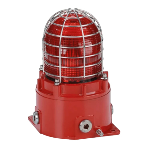
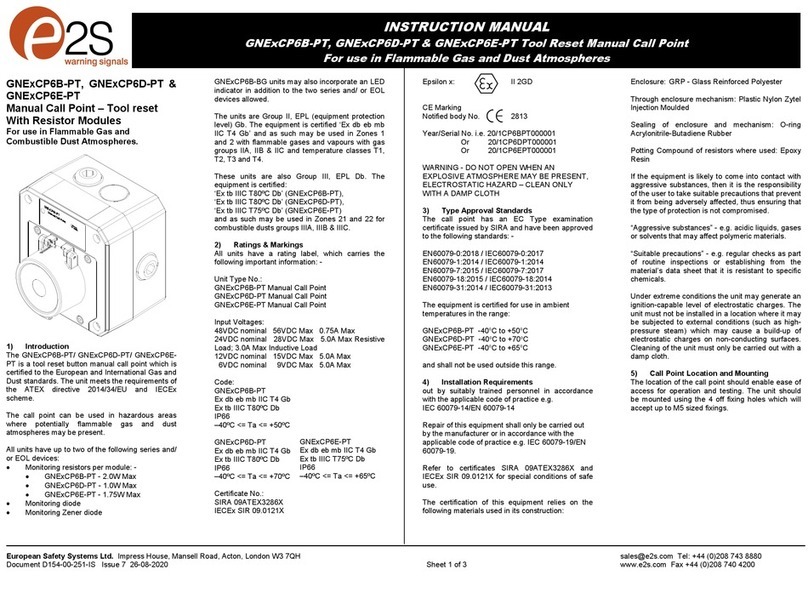
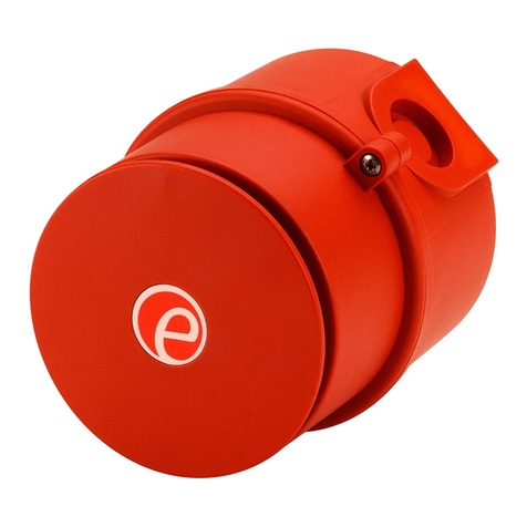
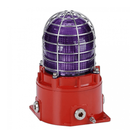
  9. E2S SONFL1H-HO Series User manual

E2S SONFL1H-HO Series User manual


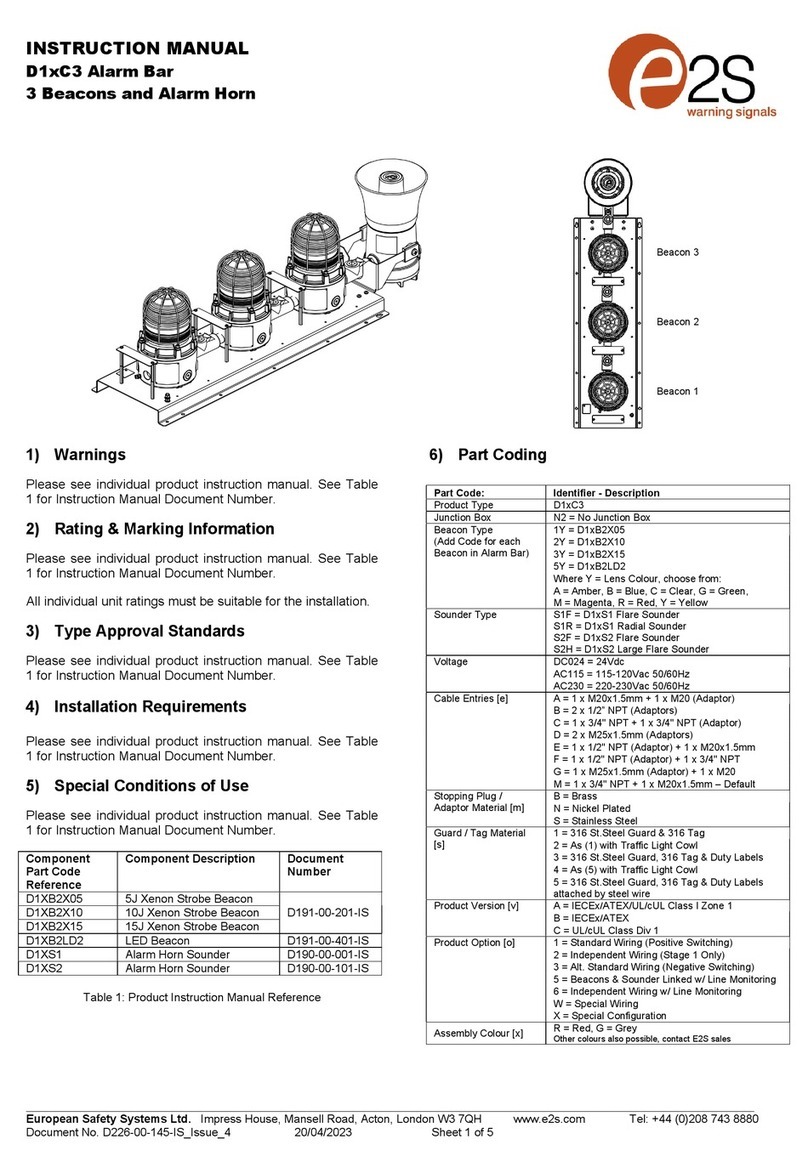
E2S Warning Signals Impress House, Mansell Road, Acton, London W3 7QH [email protected] e2s.com Page 1 of 2 D242-00-611-IS_Issue_1 - 26/04/2021
INSTRUCTION & SERVICE MANUAL
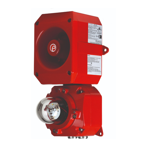
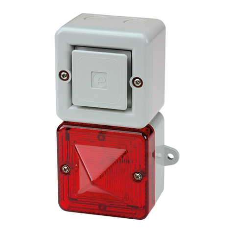
SONFL1H-HO Range - High Output Alarm Horn & L.E.D Beacon






Model No. Nominal Voltage Voltage Range Horn Nom.
Current
Beacon Nom.
Current
Sound Pressure Level dB(A)
Max Nominal
SONFL1HDC012…[X]/[Y]-H 12V dc 10-14V dc 50mA 79.5mA 105.0 @ 1m
96.0 @ 3m
103.0 @ 1m
94.0 @ 3m
SONFL1HDC024…[X]/[Y]-H 24V dc 20-28V dc 80mA* 87mA
*Current at nominal voltage on Tone 2
[X] Denotes Housing Colour: R = Red; G = Grey; W = White
[Y] Denotes Lens Colour: A = Amber; B = Blue; C = Clear; G = Green; M = Magenta; R = Red; Y = Yellow
SONFL1H-HO Combined Sounder & L.E.D Beacon
10 Selectable Tones & 2 Stages
High Output L.E.D Array
8 Flash Modes:
Steady On
Flashing - 1Hz, 1.5Hz, 2Hz
Double Strike, Triple Strike, Temporal, Blinking
CE, EAC Approved
IP Rating: IP66
Beacon is General Signalling Approved for US & Canada
UL1638A & CSA22.2 - 205-17
Clear Lens Beacon is Private Mode Fire Approved
for US & Canada UL1638, CAN/ULC-S526
Use suitable conduit or cable glands with
suitable IP or type rating 0.4Nm
5
0.5 - 1.5mm²
Terminal Connections
SONFL1H-HO
Dimensions: 172 x 86 x 83mm
Cable Entry: 2-off M20 x 1.5mm
Temp: -40°C to +55°C
Unit weight: 0.46Kg
Attention: Installation must be carried out by an electrician in compliance with the latest codes and regulations.
Attention: L'installation doit être effectuée par un électricien conformément aux derniers codes et réglementations.
Achtung: Die Installation muss von einem Elektriker gemäß den neuesten Vorschriften und Bestimmungen durchgeführt werden.
Attenzione: L'installazione deve essere eseguita da un elettricista in conformità con i codici e le normative più recenti.
Atención: La instalación debe ser realizada por un electricista de acuerdo con los últimos códigos y regulaciones.
Atenção: A instalação deve ser realizada por um eletricista de acordo com os códigos e regulamentos mais recentes.
Внимание: установка должна выполняться электриком в соответствии с последними нормами и правилами.
Attention: Disconnect from power source before installation or service to prevent electric shock
Attention: Débranchez-le de la source d'alimentation avant l'installation ou l'entretien pour éviter tout choc électrique.
Achtung: Vor Installation oder Wartung von der Stromquelle trennen, um einen Stromschlag zu vermeiden.
Attenzione: scollegare dall'alimentazione prima dell'installazione o dell'assistenza per evitare scosse elettriche.
Atención: desconéctelo de la fuente de alimentación antes de la instalación o el servicio para evitar descargas eléctricas.
Atenção: Desconecte da fonte de alimentação antes da instalação ou serviço para evitar choque elétrico
Внимание: отключите от источника питания перед установкой или обслуживанием, чтобы предотвратить поражение
электрическим током.
Noliabilityisacceptedforanyconsequencesoftheuseofthisdocument.Thetechnicalspecificaonofthisunitissubjecttochangewithoutnoceduetoourpolicyofconnual
productdevelopment.Alldimensions/weightsareapproximate.Thisunitissoldsubjecttoourstandardcondionsofsale,acopyofwhichisavailableonrequest.
DC Circuit
See D242-06-601 - Schematic Wiring
+ve IN
-ve IN
+
+
-
-
Stage 2 S2
-
+
E
-
+
E
DC
Stage 1: Apply Power to +ve & -ve
Stage 2: Apply Power to +ve & -ve & connect Stage 2 to -ve
Beacon pre-wired to Alarm terminals by default
S2
SWITCH
+-
Volume
Control
Tone Selection
(See Table)
S2 Denotes Stage 2
customer supplied
Stage switches are
BEACON
PCBA
+
-

E2S Warning Signals Impress House, Mansell Road, Acton, London W3 7QH [email protected] e2s.com Page 2 of 2 D242-00-611-IS_Issue_1 - 26/04/2021
INSTRUCTION & SERVICE MANUAL
SONFL1H-HO Range - High Output Alarm Horn & L.E.D Beacon




NOTE: Please check factory settings and ensure the correct alarm tone is selected for your country or application
Tone Selection / Header Pin Setting - Header pin settings are shown in the tone selection table. The links covered by the jumper are
shown with a black rectangle.
Torque 5Nm
Disassembly Reassembly
Mounting See D242-05-501
Loosen posi-pan screws
in four positions to
access enclosure
Access to Enclosure
98,0 [3,86]
Ø6.3 [0.25]
Cabl e Entry
Ø20.5mm [0.81"]
Rear Ø20mm Knockout
for M20 Cable Entry
if required
Pilot drilling positions
for internal mounting
holes if required
Adhere supplied
Gaskets to
backboxes to
maintain IP rating
800/1000 Hz @ 0.25 sec Alternating BS5839 Alarm Tone
500/1200 Hz @ 0.3 Hz 0.5 sec Slow Whoop NEN 2575:2000
544Hz (100mS)/440 Hz (400mS) AFNOR NF S 32-001
Simulated Bell Sound
Sweeping 800/1000 Hz @ 7 Hz Sweeping
500-1200 Hz 3.75 sec / 0.25 sec Australian Evacuation
Continuous 1000 Hz - PFEER toxic gas
Continuous 554 Hz
420 Hz @ 0.625 sec Australian Alert
1
2
3
4
5
6
7
8
9
Sawtooth 1200/500 Hz @ 1 Hz - DIN / PFEER P.T.A.P
10
8
8
8
1
1
9
10
Tone DescriptionStage 1 Stage 2
-
-
-
99dB(A) @1m
100dB(A) @1m
99dB(A) @1m
97dB(A) @1m
95dB(A) @1m
99dB(A) @1m
100dB(A) @1m
100dB(A) @1m
97dB(A) @1m
97dB(A) @1m
SONF1 dB@ 1m
12V DC and 24V DC Tone Table
DC
Tone
Settings
Tone 1
Tone 2
Tone 3
Tone 4
Tone 5
Tone 6
Tone 7
Tone 8*
Tone 9*
Tone 10*
*To set tones 8, 9 & 10 as first stage on DC, connect terminal ‘S2’ to ‘-’ terminal
Beacon Flash Settings See D228-00-001-IS
Switch
Seng FlashMode
0 0 0Steady on
1 0 0Blinking
0 1 0Flashing 1Hz*
1 1 0Flashing 1.5Hz*
0 0 1Flashing - Double Strike
1 0 1Flashing - Triple Strike
0 1 1Flashing 2Hz*
1 1 1Flashing - Temporal
Voltage Intensity (cd) at
1Hz flash rate
Intensity (cd) at
1.5Hz flash rate
Intensity (cd) at
2Hz flash rate
12V dc 5.9 5.97 6.35
24V dc 11.65 12.32 12.38
115V ac 12.99 12.65 14.1
230V ac 13.12 13.22 13.45
On-axis Light Output Rating per UL1638
1 2 3
ON
Flash Mode DIP Switch -
Shown with 1-OFF, 2-ON, 3-
OFF (0 1 0), This denotes
Flash mode 1Hz. For further
flash modes refer to table.
*Setting permitted for use as private
mode fire alarm device

This manual suits for next models

2

Other E2S Security System manuals

E2S STExB2X05-S Series User manual

E2S

E2S STExB2X05-S Series User manual

E2S D2xB1X05 Series User manual

E2S

E2S D2xB1X05 Series User manual

E2S STExB2LD2 User manual

E2S

E2S STExB2LD2 User manual

E2S BExS120D User manual

E2S

E2S BExS120D User manual

E2S D2xC2LD2 Series User manual

E2S

E2S D2xC2LD2 Series User manual

E2S BexCS11005D24DC-RD User manual

E2S

E2S BexCS11005D24DC-RD User manual

E2S D1xC3 User manual

E2S

E2S D1xC3 User manual

E2S GNExCP7-BG-S User manual

E2S

E2S GNExCP7-BG-S User manual

E2S BExBG10D-P User manual

E2S

E2S BExBG10D-P User manual

E2S STExCP8-BG-D User manual

E2S

E2S STExCP8-BG-D User manual

E2S GNExCP6B-PT User manual

E2S

E2S GNExCP6B-PT User manual

E2S BExBG05D-P-SIL User manual

E2S

E2S BExBG05D-P-SIL User manual

E2S D2 C2X05DC024 Series User manual

E2S

E2S D2 C2X05DC024 Series User manual

E2S D2xC2LD2 Series User manual

E2S

E2S D2xC2LD2 Series User manual

E2S BExCBGL2-05D-P User manual

E2S

E2S BExCBGL2-05D-P User manual

E2S D1 B2X05 Series User manual

E2S

E2S D1 B2X05 Series User manual

E2S AlertAlight AL105NH User manual

E2S

E2S AlertAlight AL105NH User manual

E2S STExB2LD2 User manual

E2S

E2S STExB2LD2 User manual

E2S BExBG05D User manual

E2S

E2S BExBG05D User manual

E2S BExBGL1D User manual

E2S

E2S BExBGL1D User manual

E2S BExCTS110-05D-P User manual

E2S

E2S BExCTS110-05D-P User manual

E2S D1xS2FDC024-S User manual

E2S

E2S D1xS2FDC024-S User manual

E2S D1xS2 Series User manual

E2S

E2S D1xS2 Series User manual

E2S GNExB2LD2 User manual

E2S

E2S GNExB2LD2 User manual

Popular Security System manuals by other brands

UTC Fire and Security Interlogix ATS125 Series Installation sheet

UTC Fire and Security

UTC Fire and Security Interlogix ATS125 Series Installation sheet

Velleman CCTVPROM18 Quick installation guide

Velleman

Velleman CCTVPROM18 Quick installation guide

Magellan MG6250 Section programming guide

Magellan

Magellan MG6250 Section programming guide

Bosch D623 Series user guide

Bosch

Bosch D623 Series user guide

Chamberlain RWV400R Setup guide

Chamberlain

Chamberlain RWV400R Setup guide

Stahl YL6S Series operating instructions

Stahl

Stahl YL6S Series operating instructions

Siemens FDM275 Mounting manual

Siemens

Siemens FDM275 Mounting manual

FireFlex Systems Inc. DUAL Owner's operation and maintenance manual

FireFlex Systems Inc.

FireFlex Systems Inc. DUAL Owner's operation and maintenance manual

Gemini GEM-P816 installation instructions

Gemini

Gemini GEM-P816 installation instructions

ROHO Smart Check Operation manual

ROHO

ROHO Smart Check Operation manual

SiKom A-Comfort quick start guide

SiKom

SiKom A-Comfort quick start guide

Opitec 105.445 manual

Opitec

Opitec 105.445 manual

Iluv SmartShaker 2 manual

Iluv

Iluv SmartShaker 2 manual

Visonic POWERMAXCOMPLETE PANEL - quick guide

Visonic

Visonic POWERMAXCOMPLETE PANEL - quick guide

Busch-Jaeger Busch-Infoline  1564 U-1 Series installation instructions

Busch-Jaeger

Busch-Jaeger Busch-Infoline 1564 U-1 Series installation instructions

Clover LCD2284DVR instruction manual

Clover

Clover LCD2284DVR instruction manual

Honeywell VISTA-32FBPT quick guide

Honeywell

Honeywell VISTA-32FBPT quick guide

resideo PROA7PLUSC Series Quick user guide

resideo

resideo PROA7PLUSC Series Quick user guide

manuals.online logo
manuals.online logoBrands
  • About & Mission
  • Contact us
  • Privacy Policy
  • Terms and Conditions

Copyright 2025 Manuals.Online. All Rights Reserved.