- 6 -
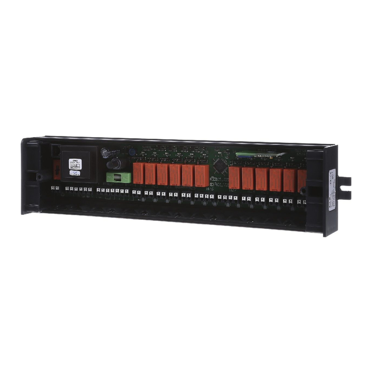
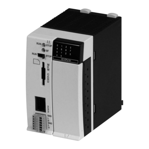
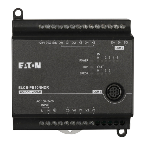
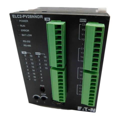
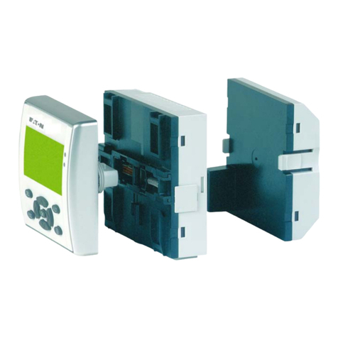
DIN Rail Mounting: When mounting the
ELCM to 35mm DIN rail, be sure to use
the retaining clip to stop any side-to-side
movement of the ELCM and reduce the
chance of wires becoming loose. The
retaining clip is at the bottom of the ELCM.
To secure the ELCM to DIN rail, pull down the clip, place it onto the rail
and gently push the clip up. To remove the ELCM, pull the retaining clip
down with a flat screwdriver and gently remove the ELCM from DIN rail.
Wiring
1. Use 12-28 AWG single-core bare wire or multi-core (stranded) wire for
the I/O wiring. The ELCM terminal screws should be tightened to 4.75
kg-cm (4.12 in-lbs) using 60/75°C copper conductor only.
2. DO NOT wire empty terminals. DO NOT place input signal wires and
power wires in the same wiring circuit.
3. DO NOT drop tiny metallic conductors into the ELCM while installing
the controller or other equipment.
Please attach the dustproof sticker to the ELCM before installing to
prevent conductive objects from dropping in.
Tear off the sticker before running the ELCM to ensure proper
ventilation.
Power Supply
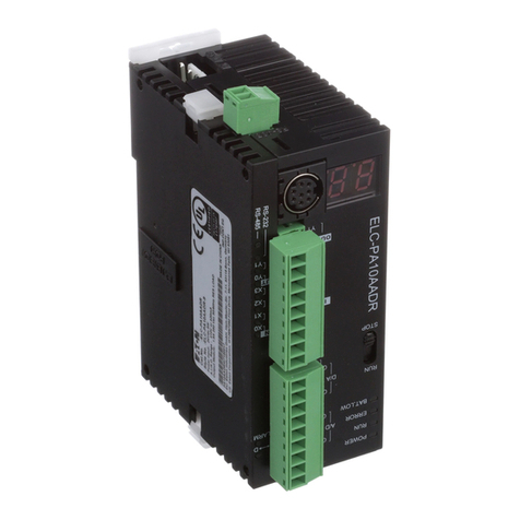
The power input type for ELCM-PH/PA controllers is AC. When operating
ELCM-PH/PA controllers, please note the following:
1. The range of the input voltage should be 100 ~ 240VAC (nominal). The
power supply should be connected to L and N terminals. Please note:
wiring 110VAC or 220VAC to +24V output terminal or any of the digital
input points will result in serious damage to the ELCM.
2. The AC power inputs for the controller and the digital I/O modules should
be ON or OFF at the same time.
3. Use 1.6mm wire (or larger) for the grounding of the ELCM.
4. A power loss for less than 10ms will not affect the operation of the ELCM.
However, longer power loss or a sustained drop of power supply voltage
will stop the running of the ELCM, and all outputs will turn “OFF”. When
proper power is restored, the ELCM will resume operation. (Please keep
this in mind when you use latched auxiliary relays and registers in your
ELCM program.)
5. The +24V output is rated at 0.5Afrom the controller. DO NOT connect
other external power supplies to this terminal. Every input terminal
requires 5 to 7mAto be driven; e.g. the 16 point input will require
approximately 100mA. Therefore, +24V terminal cannot support an
external load that is more than 400mA.
Safety Wiring
In an ELCM control system, many devices are controlled at the same time
and actions of any device could influence another device, i.e. breakdown of
