manuals.online logo
Brands
  1. Home
  2. •
  3. Brands
  4. •
  5. Eaton
  6. •
  7. Controllers
  8. •
  9. Eaton A210 Manual

Eaton A210 Manual

Instruction Leaet IL16963 Effective May 2011
Supersedes June 1989
A210, A250 Size 00, 0 or 1
Reversing Motor Controller
THE CONTROLLER
An A2l0 or A250 motor controller. when wired as shown in the
appropriate connection diagram will operate as a full voltage
starter and will give protection against overload, but not
against short-circuit currents, when wired and provided with
overload relay (OlR) heaters as listed in heater selection tables
or when used with any means of inherent protection activated
by motor temperature.
The controller should be protected against short circuits by
providing branch circuit protection not to exceed the maximum
protective device ratings listed in Table II.
This industrial type control is designed to be installed,
operated, and maintained by adequately trained workmen.
These instructions do not cover all details, variations,
or combinations of the equipment, its storage, delivery,
installation, check out, safe operation, or maintenance. Care
must be exercised to comply with local, state, and national
regulations, as well as safety practices, for this class of
equipment.
AUXILIARY CONTACTS - TYPE J
Two Jll auxiliary contacts, each with one normallyopen pole
and one normally-closed pole are supplied with reversing
controllers. One pole is used as the holding circuit auxiliary.
The other pole serves as an electrical interlock. A maximum
of three auxiliary units can be installed in each reversing
contactor with terminals either in line or in a right angle
relationship to the power poles. Auxiliary contacts mount by
means of a spring clip and retainer screw. To remove the unit
rotate the retainer screw several times (counterclockwise)
and then slide the auxiliary contact unit out of the recess.
Figure 1. Size 1 A210 and A250 Motor Controllers
2EATON CORPORATION www.eaton.com
Instruction Leaet IL16963
Effective May 2011
A210, A250Size 00, 0 or 1
Reversing Motor Controller
TYPE B OVERLOAD RELAY (See Figure 1)
This A210 or A250 motor controller is usually equipped with a
Type B block type ambient compensated overload relay (with gray
reset rod). The controller can also be supplied with a non-ambient
compensated overload relay (with red reset rod). The relay is of
the bimetal actuated type equipped with a normally-closed control
contact. An optional isolated normally-open control circuit contact is
available for field mounting. When the overload relay trips, a yellow
dot will appear flush with the molded surface below the reset rod.
Resetting the relay returns this indicator to its normal concealed
position.
TYPE A OVERLOAD RELAY (See Figure 4)
The A210 or A250 motor controller can be equipped with a Type A
block type non-ambient compensated overload relay (unmarked and
with red reset rod) or with a block type temperature compensated
overload relay (marked “ambient compensated” and with gray reset
rod). The relay is of the bimetal actuated type equipped with trip
indicator, trip adjustment covering ± 15% of rating and a normally-
closed control contact. It may be operated with either hand or
automatic reset.
Reset operation is determined by the positionof the plate on the load
side of the overload base. Position the reset plate away from the
panel to set the “hand” position. Loosen the locking screw, move
the reset plate toward the panel, and retighten the screw to set the
“auto” position.
Automatic reset should not be used with 2-wire control circuits
where automatic starting of the motor may be hazardous.
Figure 2. A210 Dimension Drawing (Dim. in inches)
Figure 3. A250 Dimension Drawing (Dim. in inches)
Figure 4. Type A Block Overload Relay (OLR)
3
Instruction Leaet IL16963
Effective May 2011
EATON CORPORATION www.eaton.com
A210, A250Size 00, 0 or 1
Reversing Motor Controller
HEATERS
Heaters are not included with the motor controller and must be
ordered separately per the heater selection table and the information
listed below. When installing heaters be sure that connecting
surfaces are clean and heaters are attached securely to the relay
in the proper location with the screw provided. The trip rating of a
heater in a 400C Ambient is 125% of the minimum full load current
shown in Table I. When tested at 600 percent of its trip rating, the
relay will trip In 20 seconds or less.
Heaters should be selected on the basis of the actual full load
current and service factor as shown on the motor nameplate or in
the manufacturer’s published literature. When the service factor of
the motor is 1.15 to 1.25, select heaters from the heater application
table. If the service factor of the motor is 1.0, or there is no service
factor shown, or a maximum of 115% protection is desired, select
one size smaller heater than indicated. When motor and overload
relay are in different ambients and when using non-compensated
overload relays, select heaters from the table using adjusted motor
currents as follows: decrease rated motor current 1 % for each ·C
motor ambient exceeds controller ambient. Increase rated motor
current 1% for each OC controller ambient exceeds motor ambient.
COIL
The A210 or A250 motor controller is available with single or dual
voltage coils. When equipped with a single voltage coil, each
contactor is wired as shown in Figure 7, 8, 9, or 10. A connection
diagram for a dual voltage coil is shown in Figure 5. When supplied
with dual voltage coils, the motor controller is normally wired for the
higher voltage connection. The wiring may be changed to the lower
voltage connection by removing and reconnecting the jumpers as
illustrated below.
WARNING
TO PROVIDE CONTINUED PROTECTION AGAINST FIRE AND SHOCK HAZ-
ARD, THE COMPLETE OVERLOAD RELAY MUST BE REPLACED IF BUMOUT
OF A CURRENT ELEMENT OCCURS. SEE TABLE II.
4EATON CORPORATION www.eaton.com
Instruction Leaet IL16963
Effective May 2011
A210, A250Size 00, 0 or 1
Reversing Motor Controller
SHORT-CIRCUIT WITHSTAND RATINGS
This motor controller is suitable for use on a circuit capable of
delivering not more than the current (rms symmetrical amperes)
shown below in circuits rated not more than the voltage shown
below:
Figure 5. Dual Voltage Coil Connections
REPLACEMENT COIL: ORDER BY PART NUMBER,
VOLTAGE, AND FREQUENCY
AC COIL DATA, (TYPICAL VALUES)
SIZE 00, 0 AND 1
Inrush Sealed sealed Pickup Droput
VA VA Watts (Time in milliseconds)
160 25 7.8 16-24 12-16
1 Instantaneous Adjustable Trip 2 Circuit Breaker
3Inverse-Time Circuit Breaker
4Instantaneous Adjustable Trip with Current-Limiting Attachment
5Inverse-Time Current-Limiting Breaker.
Figure 6. Control Station Connection Diagrams
5
Instruction Leaet IL16963
Effective May 2011
EATON CORPORATION www.eaton.com
A210, A250Size 00, 0 or 1
Reversing Motor Controller
Figure 7. A210 Connection Diagram (Type B OLR)
Figure 8. A210 Connection Diagram (Type A OLR)
Figure 9. A250 Connection Diagram (Type B OLR)
Figure 10. A250 Connection Diagram (Type A OLR)
Eaton Corporation
Electrical Sector
1111 Superior Ave.
Cleveland, OH 44114
United States
877-ETN-CARE (877-386-2273)
Eaton.com
© 2011 Eaton Corporation
All Rights Reserved
Publication No. IL16963 / 001
May 2011
Eaton is a registered trademark of Eaton
Corporation.
All other trademarks are property of their
respective owners.
Instruction Leaet IL16963
Effective May 2011
A210, A250Size 00, 0 or 1
Reversing Motor Controller
MAINTENANCE - First Turn Off Power
To Inspect Contacts
Refer to Figure 11. Loosen the two arc box assembly screws (7)
located immediately above and below the nameplate and remove
the arc box (8). Contacts (5) are visible. Retighten the screws per
Table V.
To Replace Contacts
After removing the arc box and with replacement contacts at hand,
compress the overtravel spring (12) and remove the moving contact
(5) from the crossbar (6). Disconnect any power cables. Remove the
retaining screws (11) and lift out the stationary contact assembly
(14).
To replace contacts, reverse the above procedure, making sure that
stationary contacts are secure (see Table V), moving contacts are
free to move, overtravel springs are seated and the crossbar moves
freely when the arc box is in position.
The silver cadmium oxide contact buttons need NO dressing or
lubricant throughout their life. Important - Replace all contacts and
springs as a group to avoid misalignment.
To Replace The Coil
Refer to Figure 11. Loosen the assembly screws (10) located to the
immediate top and bottom of the arc box.
Remove connector straps to the overload relay. Pull the loosened
upper base structure (9) forward. Pull the coil (1) from the upper
base, plug in a new coil, replace the upper base structure and
check the auxiliary contacts for secureness when repositioning the
upper base. Tighten the assembly screws and the connector straps
screws. Refer to Table V.
Magnet - Armature Assembly
Self alignment and permanent air gap features of the magnet
armature make replacement unnecessary. Mating pole face surfaces
should be kept clean.
Arc box must be in place when the contactor interrupts a circuit.
Figure 11. Size 1 Contactor (exploded View)

This manual suits for next models

1

Other Eaton Controllers manuals

Eaton A201 Manual

Eaton

Eaton A201 Manual

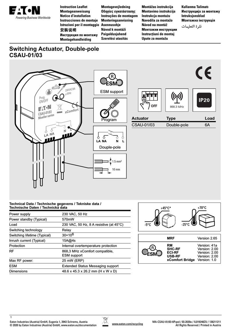
Eaton xComfort CSAU-01/03 User manual

Eaton

Eaton xComfort CSAU-01/03 User manual

Eaton Xcomfort CSAU-01/01 User manual

Eaton

Eaton Xcomfort CSAU-01/01 User manual

Eaton xComfort CJAU Series User manual

Eaton

Eaton xComfort CJAU Series User manual

Eaton Ampgard 720A Programming manual

Eaton

Eaton Ampgard 720A Programming manual

Eaton ATC-900 User manual

Eaton

Eaton ATC-900 User manual

Eaton xComfort CSAP-01/XX User manual

Eaton

Eaton xComfort CSAP-01/XX User manual

Eaton EZD Series User manual

Eaton

Eaton EZD Series User manual

Eaton FC6 User manual

Eaton

Eaton FC6 User manual

Eaton SVCH0203 SPX Advanced Instructions for use

Eaton

Eaton SVCH0203 SPX Advanced Instructions for use

Eaton Digitrip RMS Manual

Eaton

Eaton Digitrip RMS Manual

Eaton PKE-SWD-32 Manual

Eaton

Eaton PKE-SWD-32 Manual

Eaton CAAE-01/01 Manual

Eaton

Eaton CAAE-01/01 Manual

Eaton EMS2 SWD Series User manual

Eaton

Eaton EMS2 SWD Series User manual

Eaton xComfort Room Controller Touch User manual

Eaton

Eaton xComfort Room Controller Touch User manual

Eaton XV-102 Series User manual

Eaton

Eaton XV-102 Series User manual
Eaton QD5 User manual

Eaton

Eaton QD5 User manual

Eaton PKZM01 Series Manual

Eaton

Eaton PKZM01 Series Manual

Eaton AMPGARD Manual

Eaton

Eaton AMPGARD Manual

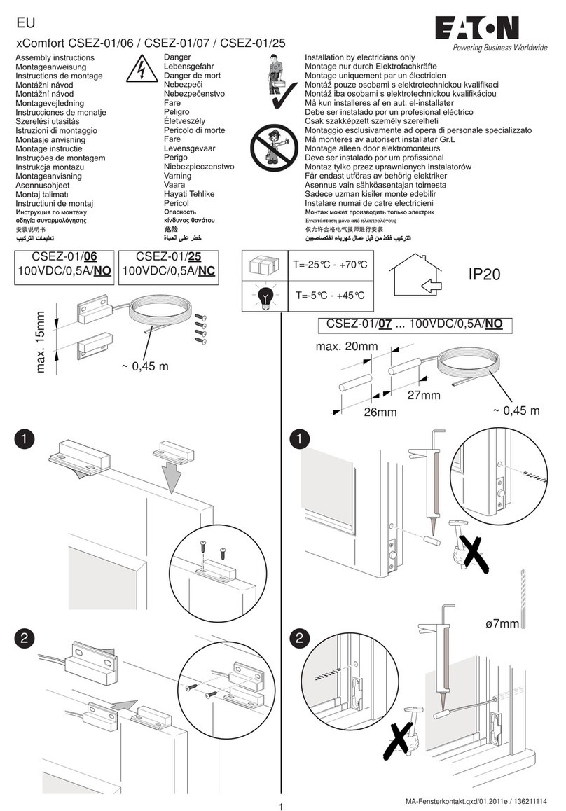
Eaton xComfort CSEZ-01/19 User manual

Eaton

Eaton xComfort CSEZ-01/19 User manual

Eaton BLR-ACX User manual

Eaton

Eaton BLR-ACX User manual

Eaton CEAG ZB-S Service manual

Eaton

Eaton CEAG ZB-S Service manual

Eaton CGLine+ CGVision Series Operating and maintenance instructions

Eaton

Eaton CGLine+ CGVision Series Operating and maintenance instructions

Eaton EM4-201-DX2 User manual

Eaton

Eaton EM4-201-DX2 User manual

Popular Controllers manuals by other brands

Castle Creations Phoenix-80 manual

Castle Creations

Castle Creations Phoenix-80 manual

ICP DAS USA I-8091 user manual

ICP DAS USA

ICP DAS USA I-8091 user manual

Unika PR-1V Operation manual

Unika

Unika PR-1V Operation manual

Rain Bird IQNCCEN Installation/configuration

Rain Bird

Rain Bird IQNCCEN Installation/configuration

ABB COMMANDER 360 user guide

ABB

ABB COMMANDER 360 user guide

YOKOGAWA UTAdvanced UT32A technical information

YOKOGAWA

YOKOGAWA UTAdvanced UT32A technical information

Lightronics AS40L owner's manual

Lightronics

Lightronics AS40L owner's manual

AMX NetLinx NI-3101-SIG Dimension Guide

AMX

AMX NetLinx NI-3101-SIG Dimension Guide

Bard BrightStat  8403-081 INSTALLATION AND APPLICATION INSTRUCTIONS

Bard

Bard BrightStat 8403-081 INSTALLATION AND APPLICATION INSTRUCTIONS

HIMA HIMatrix F3 DIO 16/8 01 manual

HIMA

HIMA HIMatrix F3 DIO 16/8 01 manual

CORNING Falcon 357469 instruction manual

CORNING

CORNING Falcon 357469 instruction manual

DAQ system USB-LT02 user manual

DAQ system

DAQ system USB-LT02 user manual

Nelson SoloRain 8010 instructions

Nelson

Nelson SoloRain 8010 instructions

Sonance AF12 installation instructions

Sonance

Sonance AF12 installation instructions

Kisi Controller Pro 1.1 Handbook

Kisi

Kisi Controller Pro 1.1 Handbook

G-Scale Graphics RailBoss 4 Basic Operation and installation manual

G-Scale Graphics

G-Scale Graphics RailBoss 4 Basic Operation and installation manual

Advantech Celeron M Universal Network Controller with PC/104 Extension... user manual

Advantech

Advantech Celeron M Universal Network Controller with PC/104 Extension... user manual

Toshiba 2000 user manual

Toshiba

Toshiba 2000 user manual

manuals.online logo
manuals.online logoBrands
  • About & Mission
  • Contact us
  • Privacy Policy
  • Terms and Conditions

Copyright 2025 Manuals.Online. All Rights Reserved.