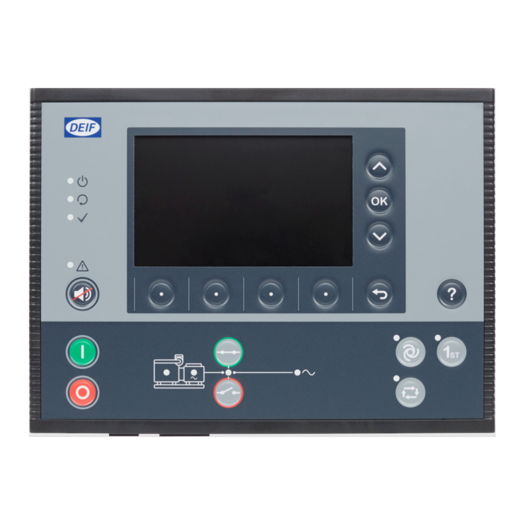
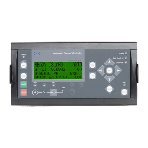
Deif AGC-4 Mk II User manual

AGC-4 Mk II
Analogue controller and transducer outputs
Options EF5, EF6 and F1
4189341277C

1. Description of options
1.1 ANSI numbers................................................................................................................................................................................................................................3
1.2 Software version.........................................................................................................................................................................................................................3
1.3 Parameters.....................................................................................................................................................................................................................................3
1.4 Option F1..........................................................................................................................................................................................................................................3
1.5 Option EF5...................................................................................................................................................................................................................................... 3
1.6 Option EF6......................................................................................................................................................................................................................................4
1.7 Warnings, legal information and safety........................................................................................................................................................................4
1.7.1 Warnings and notes...........................................................................................................................................................................................................4
1.7.2 Legal information and disclaimer.............................................................................................................................................................................. 4
1.7.3 Safety issues.........................................................................................................................................................................................................................5
1.7.4 Electrostatic discharge awareness.......................................................................................................................................................................... 5
1.7.5 Factory settings..................................................................................................................................................................................................................5
2. Function description
2.1 Analogue outputs.......................................................................................................................................................................................................................6
2.1.1 Overview..................................................................................................................................................................................................................................6
2.1.2 Using an analogue output to regulate a GOV/AVR.......................................................................................................................................... 6
2.1.3 GOV/AVR analogue controller offset........................................................................................................................................................................7
2.1.4 Using an analogue output as a transducer......................................................................................................................................................... 8
2.2 PWM duty cycle..........................................................................................................................................................................................................................9
2.2.1 Duty cycle..............................................................................................................................................................................................................................9
2.2.2 Principle of duty cycles...............................................................................................................................................................................................10
Options E F AGC-4 Mk II 4189341277C EN Page 2 of 10

1. Description of options
1.1 ANSI numbers
Function ANSI no.
Selectable ±25 mA or relay output for speed control (governor) 77
Selectable ±25 mA or relay output for voltage control (AVR) 77
PWM speed control output for CAT® engines 77
2 x 0(4)-20 mA outputs 77
1.2 Software version
This document is based on the AGC-4 Mk II software version 6.00.0.
1.3 Parameters
The relevant parameters are 2781, 2783, and 5690 to 5991. For more information, see the Parameter list.
1.4 Option F1
Option F1 is a hardware option: A PCB installed in slot #6, in addition to the standard hardware.
Term. Function Description
90 Not used
91 0 Transducer output 91
92 0(4)-20 mA
93 Not used
94 Not used
95 0 Transducer output 95
96 0(4)-20 mA
97 Not used
1.5 Option EF5
Option EF5 is a hardware option: A PCB installed in slot #4. The PCB replaces the standard relay PCB in slot #4. The PWM
(Pulse Width Modulated) speed output is intended for Caterpillar® electronic engine control systems ADEM and PEEC.
Term. Function Description
65 ±25 mA AVR set point output.
66 0
67 PWM + PWM speed governor signal.
68 PWM -
69 NO Relay output for AVR. Raise voltage.
70 Com.
Options E F AGC-4 Mk II 4189341277C EN Page 3 of 10

Term. Function Description
71 NO Relay output for AVR. Lower voltage.
72 Com.
NOTE Connect PWM - to the engine battery negative and PWM + to the engine control system S-SPD (speed) input
(called RATED SPEED on the ADEM controller and PRIMARY THROTTLE on the PEEC controller).
1.6 Option EF6
Option EF6 is a hardware option: A PCB installed in slot #4. The PCB replaces the standard relay PCB in slot #4. The PWM
(Pulse Width Modulated) speed output is intended for Caterpillar® electronic engine control systems ADEM and PEEC.
Term. Function Description
65 Not used
66 Not used
67 0 Speed governor, AVR or transducer output 68
68 ±25 mA
69 PWM - PWM speed governor signal
70 PWM +
71 0 Speed governor, AVR or transducer output 72
72 ±25 mA
NOTE Connect PWM - to the engine battery negative and PWM + to the engine control system S-SPD (speed) input
(called RATED SPEED on the ADEM controller and PRIMARY THROTTLE on the PEEC controller).
1.7 Warnings, legal information and safety
1.7.1 Warnings and notes
Throughout this document, a number of warnings and notes with helpful user information will be presented. To ensure that
these are noticed, they will be highlighted as follows in order to separate them from the general text.
Warnings
DANGER!
This shows dangerous situations.
If the guidelines are not followed, these situations will result in death, serious personal injury, and equipment
damage or destruction.
Notes
NOTE Notes provide general information, which will be helpful for the reader to bear in mind.
1.7.2 Legal information and disclaimer
DEIF takes no responsibility for installation or operation of the generator set. If there is any doubt about how to install or
operate the engine/generator controlled by the Multi-line 2 unit, the company responsible for the installation or the
operation of the set must be contacted.
NOTE The Multi-line 2 unit is not to be opened by unauthorised personnel. If opened anyway, the warranty will be lost.
Options E F AGC-4 Mk II 4189341277C EN Page 4 of 10

Disclaimer
DEIF A/S reserves the right to change any of the contents of this document without prior notice.
The English version of this document always contains the most recent and up-to-date information about the product. DEIF
does not take responsibility for the accuracy of translations, and translations might not be updated at the same time as the
English document. If there is a discrepancy, the English version prevails.
1.7.3 Safety issues
Installing and operating the Multi-line 2 unit may imply work with dangerous currents and voltages. Therefore, the
installation should only be carried out by authorised personnel who understand the risks involved in working with live
electrical equipment.
DANGER!
Be aware of the hazardous live currents and voltages. Do not touch any AC measurement inputs as this could lead
to injury or death.
1.7.4 Electrostatic discharge awareness
Sufficient care must be taken to protect the terminals against static discharges during the installation. Once the unit is
installed and connected, these precautions are no longer necessary.
1.7.5 Factory settings
The unit is delivered from the factory with default settings. These are not necessarily correct for the engine/generator set.
Check all the settings before running the engine/generator set.
Options E F AGC-4 Mk II 4189341277C EN Page 5 of 10

2. Function description
2.1 Analogue outputs
2.1.1 Overview
The analogue outputs are active and galvanically separated. No external supply can be connected.
The current outputs can be converted to any voltage in the range ±10 V DC by mounting a resistor across the terminals.
Resistor example
A 400 Ω resistor across the terminals of the ±25 mA output supplies ±10 V DC.
NOTE The choice of resistor depends on the governor. Place the resistor at the governor/AVR end to avoid the signal
being disturbed by noise. For more information, see Interfacing DEIF Equipment with Governors and AVRs and
General Guidelines for Commissioning.
2.1.2 Using an analogue output to regulate a GOV/AVR
You can use an analogue output to regulate a governor or AVR.
Governor analogue output setup example
To set up transducer 68 of option EF6 to transmit the governor set point as a 0 to 20 mA signal:
In Reg. output GOV, menu 2781, for Set point, select Analogue.
In Governor output, menu 5981, for Transducer A, select Transducer 68.
In AOUT 68 Limits, menu 5781, select the minimum limit, that is, 0 mA.
In AOUT 68 Limits, menu 5782, select the maximum limit, that is, 20 mA.
Output limits
You can limit the analogue output's maximum and minimum output if the full range is not needed. This can especially be
useful when using the analogue output for governor control, since some governors only accept a specific voltage range.
In the following example, analogue output 68 with a standard output of ±25 mA (option EF6) is limited to an output of 0 to
20 mA to be used for governor control.
Options E F AGC-4 Mk II 4189341277C EN Page 6 of 10

0 %
20 %
40 %
60 %
80 %
100 %
0 mA
20 mA
Regulator output
0 %
20 %
40 %
60 %
80 %
100 %
-25 mA
25 mA
Regulator output
NOTE The menus used for setting up the regulation output limits are 5780 to 5810. The menus available are option-
dependent.
2.1.3 GOV/AVR analogue controller offset
In addition to the controller parameters, this additional setting can be used. The purpose of this setting is to give the
analogue output an offset value when powering up the unit. Furthermore, a digital input can be used to reset the output to
the offset value. The offset value must be adjusted so the genset will start up at the correct speed and voltage.
The offset always refers to the analogue output limits. When the engine is stopped the controller outputs are reset to the
analogue offset value. The initial speed/voltage adjustment is typically made on the speed governor/AVR itself. The output
for the GOV/AVR can be inverted by selecting Inverse proportional in parameters 2781/2783.
The following drawing is for option EF6, with the output limits set to ±25 mA.
Options E F AGC-4 Mk II 4189341277C EN Page 7 of 10

Controller offset
100%
0%
25mA
-25mA
2.1.4 Using an analogue output as a transducer
You can use an analogue output as a transducer to transmit the controller's set point, AC measurements or power
management information to an external system.
You can select the output range for the transducer. That is, 0-20mA, 4-20mA, 0-10V, or -10-0-10V.
You can also select the output range for the value. For example, for the genset apparent power (menu 5850), select the
minimum in 5855, and select the maximum in 5844.
Parameters for using an analogue output as a transducer
Menu Value Details
5690 P ref
The controller's power set point.
For example, for MWM TEM controllers.
5700 Q ref The controller's reactive power set point
5710 cos phi ref The controller's cos phi set point
5820 P1* Genset active power
5830 P2* Genset active power
5840 P3* Genset active power
5850 S Genset apparent power
5860 Q Genset reactive power
5870 cos phi cos phi of the power from the genset
5880 f Genset frequency
5890 U Genset L1-L2 voltage
Options E F AGC-4 Mk II 4189341277C EN Page 8 of 10

Menu Value Details
5900 I Genset L1 current
5910 U Busbar L1-L2 voltage
5920 f Busbar frequency
5930 Input 102 The value received by analogue input 102.
5940 Input 105 The value received by analogue input 105.
5950 Input 108 The value received by analogue input 108.
5960 P total consumed The total power produced in the power management system.
5970 P total available The additional power that the power management system could supply without starting more
gensets.
*Note: P1, P2 and P3 are identical. For example, P1 can be used as an input to a switchboard instrument, while P2 can be an
input to a PLC.
Available power transducer setup example
To set up transducer 66 to transmit the available power (0 to 10 MW) as a 4 to 20 mA signal:
In menu 5973, for Set point, select 4-20mA. For Transducer A, select Transducer 66.
In menu 5975, select the minimum value (this corresponds to 4 mA), that is, 0 kW.
In menu 5974, select the maximum value (this corresponds to 20 mA), that is, 10000 kW.
NOTE These values are also available through Modbus.
2.2 PWM duty cycle
2.2.1 Duty cycle
The PWM signal has a frequency of 500 Hz ±50 Hz. The resolution of the duty cycle is 12 bits, which gives 4095 output
levels. The output is an open collector output with a 1 kΩ pull-up resistor.
The low level of the signal is between 0 and 0.5 volts, and the high level is between 5.7 and 6 volts.
Time
Voltage
0 0.5 V
5.7...6 V
0 100 % duty
cycle
Options E F AGC-4 Mk II 4189341277C EN Page 9 of 10

2.2.2 Principle of duty cycles
The drawing below shows an example of a 10% duty cycle:
Duty cycle = 10 %
The drawing below shows an example of a 90% duty cycle:
Duty cycle = 90 %
When used as transducer outputs, the signal can be connected directly to 4-20 mA instruments as shown below.
Out
0-
+
Transducer output 4-20 mA instrument or similar
NOTE It is recommended to use instruments from the DQ series of DEIF instruments. Please refer to www.deif.com for
more information.
Options E F AGC-4 Mk II 4189341277C EN Page 10 of 10
Other manuals for AGC-4 Mk II
2
This manual suits for next models
3
Table of contents
Other Deif Controllers manuals
Deif
Deif SGC 420 Mk II User manual
Deif
Deif GC-1F User manual
Deif
Deif iE 250 User manual
Deif
Deif GPC-3 Hydro User manual

Deif
Deif ASC Series User manual
Deif
Deif AGC 150 User manual
Deif
Deif AGC 200 Series User manual
Deif
Deif SGC 420 User manual
Deif
Deif Multi-line 2 User manual

Deif
Deif AGC 200 Series User manual


