Eaton SDR-RINT User manual

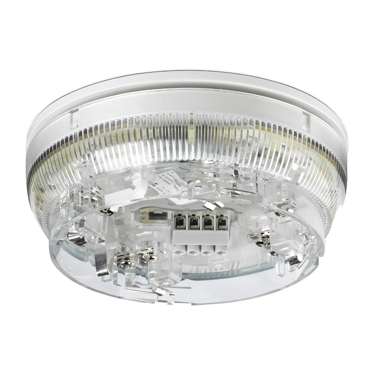
SDR-RINT Internal Radio Sounder
Installation Instructions
Introduction
The Eaton SDR-RINT Internal
Radio Sounder produces
sounds to indicate alarms,
entry tones, exit tones and
other conditions. The sounder
is the radio equivalent of the
Eaton Internal Wired Sounder.
The sounder is intended for
use in areas that are out of
audio range of keypads or
panels but where users need
to hear system sounds.
The sounder can
communicate with a radio
expander or a control
unit that has built-in radio
communications. The sounder is compatible with both i-on and
Menvier intrusion systems.
Note:
•The sounder uses four AA batteries.You can use an optional 12Vdc
external supply to extend battery life.
•The maximum number of internal sounders you can use is
dependent on the intrusion system. For details of system limits,
please refer to the appropriate engineering guide.
•The sounder requires control unit software v4.05 or higher and if
applicable, radio expander software v2.09 or higher.
•If you are using expanders, it is advisable to distribute both internal
and external sounders across different expanders to maintain good
response times.
This product must be installed by qualified service personnel.

Page 2
Installing the sounder
Step 1: Choose a location
Make sure the device is not located:
•Closer than one metre to mains wiring,
metal water or gas pipes, or other metal
structures.
•Inside metal enclosures.
•Next to computers, photocopiers, radio
equipment, CAT 5 data lines or industrial
mains equipment.
•Near sources of electromagnetic or
radio interference.
Step 2: Check the signal strength
Before installation, you should carry out
a radio signal-strength survey using the
Eaton DET-RSURV01 Radio Survey Tool at
all locations where you intend to install
radio devices.
If the tool is not available, you can use the
Signal Strength
option at the control unit
(Step 7).
For advice about the installation of radio
devices, please refer to the document
titled “Guidance Notes for Wireless Alarm
System Installations”.
Step 3: Fit the batteries
ote:N
•You must fit the supplied AA batteries,
even if you power the sounder
externally. The batteries prevent loss
of operation in the event of a power
failure.
•Batteries and the unit itself must be
disposed of in accordance with WEEE
regulations and any other local and
national regulations.
•The sounder sends a “Low Battery”
message to the control unit when the
battery is low.
To fit the batteries, remove the front cover
(see Figure 1) and insert the batteries in the
cradles (see Figure 2).
The LEDs flash to indicate the firmware
version number (see “LED operation” on
page 4).
Leave the cover off until Step 7.
1
Flip down the screw covers
and remove the screws
2
Lift the cover off its hinges
Figure 1. Removing the front cover
LEDs
Battery cradles
Figure 2. Battery cradles and LEDs
Step 4: Add the sounder
Before you start this step:
•Ensure that the intrusion system is
powered up and that you have carried
out initial configuration.
•Place the sounder near a keypad that is
within radio range of the control unit or
expander.
To add the internal sounder, select the
appropriate Installer option that adds an
internal sounder, as described in your
Engineering Guide. For example, if you are
using an i-on Next Generation control unit:
1. Choose
Detectors/Devices, Internal
Sounders, Add/Del Sounder
:
INTERNAL SOUNDERS
Add/Del Sounder >

Page 3
2. If prompted, select the expander you
want the sounder to communicate with.
3. If you are using more than one
sounder, use uor nand press to
choose a sounder number (name):
ADD/DEL SOUNDER
Int. SNDR 01 >
(A * character is displayed to the left
of the name if the sounder is already
known to the system.)
4. When prompted, press the sounder’s
tamper switch:
Activate
Sounder Tamper >
After a few seconds, you see:
ADD/DEl SOUNDER
Sounder added SS: 9
The value on the second line indicates
the signal strength (1-9).
5. Press .You have now added the
sounder and the system knows its
identity.
If you need to remove the sounder from
the system, repeat the process, but choose
to delete the sounder when prompted.
Step 5: Edit the properties
If you wish to change the name of the
sounder, assign it to partitions\wards or
change the volume, use the appropriate
Edit option. For example, if you are using
i-on Next Generation, use
Detectors/
Devices, Internal Sounders, Edit Sounder
.
Step 6: Mount the sounder
Fix the backplate to the wall or backbox
(Figure 3). If you are using an external
12Vdc power supply, connect it to the
terminal block (Figure 1).
Refit the cover and secure with the screws.
Cable-entry hole
(and on each side)
Use the supplied 3mm x 19mm
(No4) screw for the tamper block
Minimum 3
off 4mm x
25mm (No8)
countersunk
screws for
backplate
Figure 3. Mounting the backplate
Step 7: Confirm signal strength
Test signal strength using the appropriate
Installer option, as described in your
Engineering Guide. For example, if you are
using an i-on Next Generation control unit:
1. Select
Test, Signal Strengths, Internal
Sounders
.
2. If you are using more than one
sounder, press uor nto select the
sounder.
The signal strength is displayed at the
end of the second line:
SIGNAL STRENGTHS
Int. SNDR 01 9(8)
In this example, the reading is 9, with a
lowest recorded value of 8.
A reading of 9 is the highest. 5 or
above is good, 3 to 4 is marginal and 2
or below is not acceptable.
The value is updated when the tamper
switch changes state, the external
supply is switched on or off, every 10
seconds when the sounder is making
a sound, and every 4 minutes at other
times.
If you wish to test sounder operation,
choose
Test, Sirens & Sounders, Internal
Sounders
.

Page 4
LED operation
When you connect the batteries, the
number of flashes of the red and green
LEDs indicate the firmware version
number. For example, one flash of red and
two of green indicates version 1.2.
The LEDs also indicate signal strength at
the start of a sounder test or when the
sounder receives a message, providing
the tamper switch is activated (that is,
the cover is off). The signal strength is
indicated as follows:
•Red, amber and green lit: good
•Red and amber lit: adequate
•Only red lit: not satisfactory
Using an external supply
If fitted, an external power supply provides
all power for radio activity and disables
battery-saving features, such as to prevent
long-running tones. An external power
supply is not a substitute for the internal
batteries, since these are required in the
event of a power failure.
Specications
Type of Warning Device: Internal, self-powered,
tone output.
External Supply (optional): 6-15Vdc, 150mA,
compliant with EMC:2014/30/EU, Low voltage:
2014/35/EU. Ensure correct polarity when
connecting.
Current consumption: Active current 100mA.
Quiescent current 30 uA when powered by
batteries, or 12 mA when powered externally.
Sound Output: 80 dB(A) @ 1m.
Radio Frequency: 868.6625 MHz narrowband.
Radio Power: 10mW.
Range: Min. of 500m in free space.
Cut-off Period: Auto-silences after 3 minutes if
powered only by batteries.
Case Material: Polycarbonate.
Intrusion Standards: PD6662:2010,
EN50131-4:2009.
Certification Body: Telefication.
Security Grade: Grade 2.
Environmental Class: Class II.
Battery: 4 x 1.5Vdc AA alkaline. Nominal voltage:
6Vdc. Low-level warning: 4.5Vdc.
End of life: 3.75Vdc. Battery life:Typically 12
months when powered only by batteries,
assuming a total of 80 seconds per day of entry/
exit tones.
Weight: 275g (with batteries).
Operating Temp. Range: -10°C to +55°C.
Relative Humidity: 0 to 95% non-condensing.
Dimensions: 127mm(h) x 127mm(w) x 40mm(d).
SIMPLIFIED EU DECLARATION OF CONFORMITY
Hereby, Eaton Electrical Products Ltd declares
that the radio equipment type SDR-RINT is in
compliance with Directive 2014/53/EU.
The full text of the EU declaration of conformity
is available at the following internet address:
www.touchpoint-online.com
The information, recommendations, descriptions and safety
notations in this document are based on Eaton Corporation’s
(“Eaton”) experience and judgment and may not cover all
contingencies. If further information is required, an Eaton sales office
should be consulted. Sale of the product shown in this literature is
subject to the terms and conditions outlined in appropriate Eaton
selling policies or other contractual agreement between Eaton and
the purchaser.
THERE ARE NO UNDERSTANDINGS, AGREEMENTS, WARRANTIES,
EXPRESSED OR IMPLIED, INCLUDING WARRANTIES OF FITNESS
FOR A PARTICULAR PURPOSE OR MERCHANTABILITY, OTHER
THAN THOSE SPECIFICALLY SET OUT IN ANY EXISTING CONTRACT
BETWEEN THE PARTIES. ANY SUCH CONTRACT STATES THE ENTIRE
OBLIGATION OF EATON. THE CONTENTS OFTHIS DOCUMENT
SHALL NOT BECOME PART OF OR MODIFY ANY CONTRACT
BETWEEN THE PARTIES.
In no event will Eaton be responsible to the purchaser or user in
contract, in tort (including negligence), strict liability or other-wise
for any special, indirect, incidental or consequential damage or loss
whatsoever, including but not limited to damage or loss of use of
equipment, plant or power system, cost of capital, loss of power,
additional expenses in the use of existing power facilities, or claims
against the purchaser or user by its customers resulting from the use
of the information, recommendations and descriptions contained
herein. The information contained in this manual is subject to change
without notice.
© 2016 Eaton.
Eaton, Security House, Vantage Point Business Village,
Mitcheldean, GL17 0SZ. www.touchpoint-online.com
Product Support (UK) Tel: +44 (0) 1594 541978 available
08:30 to 17:00 Monday to Friday.
email: securitytec[email protected]
Part number 12700575
Issue 4 10/07/2016
Other Eaton Marine Equipment manuals

Eaton
Eaton X10 DC User manual

Eaton
Eaton Crouse-hinds series User manual

Eaton
Eaton DEV20 User manual

Eaton
Eaton MEDC DB3BM User manual

Eaton
Eaton X 10 DC User manual

Eaton
Eaton ULCAS380 User manual

Eaton
Eaton DB3P User manual

Eaton
Eaton MEDC EV24 User manual

Eaton
Eaton X10 User manual

Eaton
Eaton DB3B User manual
Popular Marine Equipment manuals by other brands

Furuno
Furuno MU-192HD Operator's manual

Argus Security
Argus Security SGRBS100/L quick start guide

IMAGENEX
IMAGENEX 852-GS user manual

Lone Star Marine
Lone Star Marine HAULMASTER 1500 quick start guide

Furuno
Furuno FCV-1150 Specifications

Seastar Solutions
Seastar Solutions HA1230 installation instructions