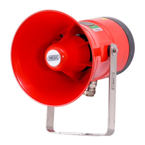
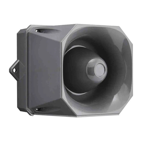
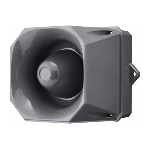
Eaton MEDC EV21 User manual

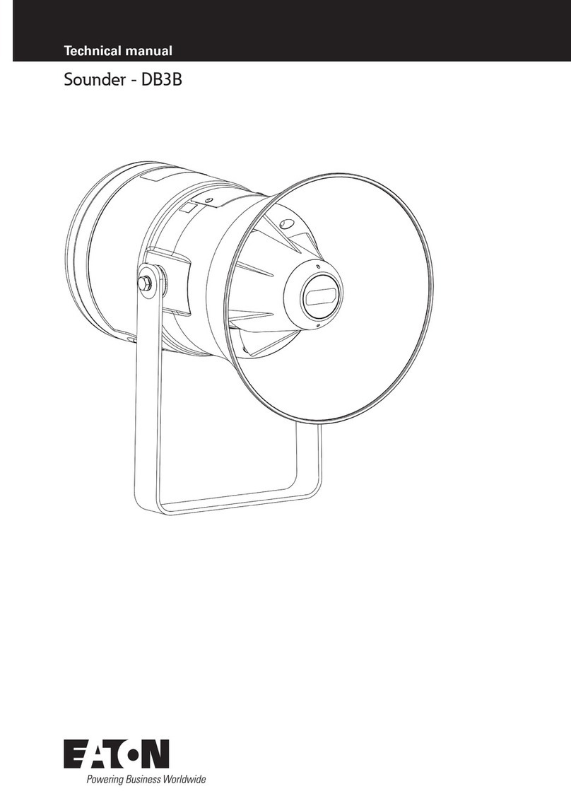
EV21 Sounder Technical Manual
Eaton MEDC technical manual

2EV21 SOUNDER TECHNICAL MANUAL TMF0048.A www.eaton.com
DISCLAIMER OF WARRANTIES AND LIMITATION OF LIABILITY
ENGLISH
The information, recommendations, descriptions and safety notations in this document are based on Eaton Corporation’s
(“Eaton”) experience and judgment and may not cover all contingencies. If further information is required, an Eaton sales
office should be consulted. Sale of the product shown in this literature is subject to the terms and conditions outlined in
appropriate Eaton selling policies or other contractual agreement between Eaton and the purchaser.
THERE ARE NO UNDERSTANDINGS, AGREEMENTS, WARRANTIES, EXPRESSED OR IMPLIED, INCLUDING
WARRANTIES OF FITNESS FOR A PARTICULAR PURPOSE OR MERCHANTABILITY, OTHER THAN THOSE
SPECIFICALLY SET OUT IN ANY EXISTING CONTRACT BETWEEN THE PARTIES. ANY SUCH CONTRACT STATES THE
ENTIRE OBLIGATION OF EATON. THE CONTENTS OF THIS DOCUMENT SHALL NOT BECOME PART OF OR MODIFY
ANY CONTRACT BETWEEN THE PARTIES.
In no event will Eaton be responsible to the purchaser or user in contract, in tort (including negligence), strict liability or
other-wise for any special, indirect, incidental or consequential damage or loss whatsoever, including but not limited to
damage or loss of use of equipment, plant or power system, cost of capital, loss of power, additional expenses in the
use of existing power facilities, or claims against the purchaser or user by its customers resulting from the use of the
information, recommendations and descriptions contained herein. The information contained in this manual is subject to
change without notice.
DEUTSCH
Die Informationen, Empfehlungen, Beschreibungen und Sicherheitshinweise in dieser Dokumentation basieren auf
den Erfahrungen und der Bewertung der Eaton Corporation („Eaton“) und sind unter Umständen nicht allumfassend.
Wenden Sie sich bitte für weitere Informationen an eine Vertriebsniederlassung von Eaton. Der Verkauf des in dieser
Informationsschrift gezeigten Produkts unterliegt den Allgemeinen Geschäftsbedingungen in den entsprechenden Eaton-
Verkaufsrichtlinien oder sonstigen vertraglichen Vereinbarungen zwischen Eaton und dem Käufer.
ES BESTEHEN KEINE VEREINBARUNGEN, VERTRÄGE ODER GEWÄHRLEISTUNGEN, EINSCHLIESSLICH GARANTIEN
DER GEBRAUCHSTAUGLICHKEIT FÜR EINEN BESTIMMTEN ZWECK ODER MARKTFÄHIGKEIT, AUSSER DEN KONKRET
IN EINEM ZWISCHEN DEN VERTRAGSPARTNERN BEREITS BESTEHENDEN VERTRAG DEFINIERTEN. JEDER DIESER
VERTRÄGE BENENNT ALLE PFLICHTEN VON EATON. DER INHALT DES VORLIEGENDEN DOKUMENTS WIRD NICHT
TEIL EINES VERTRAGES ZWISCHEN DEN PARTEIEN UND ÄNDERT DIESEN AUCH NICHT.
In keinem Fall ist Eaton gegenüber dem Käufer oder Benutzer vertraglich, aus unerlaubter Handlung (einschließlich
Fahrlässigkeit), verschuldensunabhängiger Haftung oder anderweitig für besondere, indirekte, zufällige oder Folgeschäden
oder -verluste jeglicher Art verantwortlich, einschließlich, aber nicht beschränkt auf Schäden oder Nutzungsausfall von
Geräten, technischen Anlagen oder Stromversorgungssystemen, Kapitalkosten, Stromausfall, zusätzliche Ausgaben bei der
Nutzung vorhandener Stromanlagen oder Ansprüche gegen den Käufer oder Benutzer durch seine Kunden, die sich aus der
Nutzung der hierin enthaltenen Informationen, Empfehlungen und Beschreibungen ergeben. Eaton behält sich Änderungen
der Angaben in diesem Handbuch ohne vorherige Ankündigung vor.
FRANCAIS
Les renseignements, recommandations, descriptions et consignes de sécurité mentionnés dans le présent document
s’appuient sur l’expérience et le discernement d’Eaton Corporation («Eaton») et peuvent ne pas couvrir toutes les
éventualités. Pour obtenir des informations supplémentaires, consultez un bureau de vente Eaton. La vente du produit
présenté dans le présent document est soumise aux conditions générales indiquées dans la politique de vente Eaton
concernée ou dans tout autre accord contractuel entre Eaton et l’acquéreur.
IL N’EXISTE AUCUN ACCORD, ENTENTE NI GARANTIE, EXPRESSE OU IMPLICITE, Y COMPRIS LES GARANTIES DE
CONFORMITÉ À UN USAGE PARTICULIER OU DE VALEUR MARCHANDE, AUTRES QUE CEUX EXPRESSÉMENT
ÉNONCÉS DANS UN CONTRAT EXISTANT ENTRE LES PARTIES. TOUT CONTRAT DE CE TYPE DÉCRIT L’ENSEMBLE DES
OBLIGATIONS D’EATON. LE CONTENU DE CE DOCUMENT NE DOIT PAS FAIRE PARTIE D’UN CONTRAT ENTRE LES
PARTIES NI LE MODIFIER.
En aucun cas Eaton ne saura être tenu responsable par l’acheteur ou par l’utilisateur partie au contrat, à tort (négligence
comprise) d’une responsabilité stricte ni de tout autre dommage ou perte particulier, indirect, accidentel ou conséquentiel,
de quelque type que ce soit, y compris sans y être limité tout dommage ou perte d’utilisation de l’équipement, de l’usine
ou du système d’alimentation, du coût de capital, de la perte de puissance, des dépenses supplémentaires engendrées
par l’utilisation de systèmes d’alimentation existants, ni de toute réclamation par des clients à l’acheteur ou à l’utilisateur
résultant de l’utilisation des présentes informations, recommandations et descriptions. Les informations contenues dans le
présent manuel sont susceptibles d’être modifiées sans notification préalable.
3
Table of Contents
EV21 SOUNDER TECHNICAL MANUAL TM276.A www.eaton.com
Table of contents
Sounder EV 21 / EV 24 ............................................................................4
Operation and Design .............................................................................4
Mounting .......................................................................................4
Wiring ..........................................................................................4
Choosing the signal tones 1-5 ......................................................................4
Choosing the tones 6-21...........................................................................4
Changing the Continuous tone frequency ............................................................4
Control .........................................................................................4
Changing the sound level pressure ..................................................................4
EMC-Directive ...................................................................................5
Dimensions .....................................................................................5
Circuit diagram ..................................................................................5
Connections .....................................................................................5
Technical data ...................................................................................6
Table 1 (Signals)..................................................................................6
Table 1 (Signals)..................................................................................7
User information .................................................................................8

4
EV21 Sounder Technical Manual
EV21 SOUNDER TECHNICAL MANUAL TMF0048.A www.eaton.com
Sounder EV 21 / EV 24
• Compact indoors and outdoors sounder for universal use
• 21 signal tones, switchable
• Emergency signal according to DIN 33404/3
• Sound pressure level SPL: approx. 105 dB(A)
• Suited for direct and alternating current
• Lid terminals version for security installations
• 24 VDC with 500 mA inrush current limiter for operation with PLC
• Approval VdS for automatic fire alarm installations (24 VDC) being prepared
Operation and Design
The sounder EV 21 / EV 24 is a signal generator for use indoors as well as outdoors. The robust design allows the EV
21 to be used even under difficult environmental circumstances. The device digitally generates 21 different signal tones,
which may be set by the operator. Every 3 tones build a tone group, the tones in witch may be adjusted individually in
the device itself or switched externally using voltage-free contacts.
Mounting
Mount on a firm surface. The loudspeaker front opening should not be directed upwards. This is especially
important outdoors.
Wiring
Loosen both fastening screws of the loudspeaker lid and remove the lid. Insert the feed cable and terminate on 1 and 2. The
terminals 3 and 4 can be used for looping the feed voltage. The neutral conductor should be connected with (“earth”).
Choosing the signal tones 1-5
The tones may be adjusted with the 10-pole DIP switch S1-S10 and the 3-pole terminal A-B-C.
Example: You want to choose the tones 1, 2 and 4. Choose them according to table 2, in this case using tone combination
pos. 1. Set the DIP switches 1-4 as shown. Then bridge the tone switch terminals to choose the tones you want:
Tone 1 = Bridge A-B
Tone 2 = Bridge B-C
Tone 3 = Bridge A-B + B-C
If you want to switch the tones externally, this can be done by using a 3-conductor control cable from the terminals
A-B-C and voltage-free contacts.
Choosing the tones 6-21
Use the DIP switches S1-S9 to set the tones 6-21.
Example: You want to switch tone 14.
1. Set the switches S1-S4 according to table 2, for instance like pos. 10, option 3.
2. Set the switches S5-S9 according to table 3, tone 14.
Changing the Continuous tone frequency
(Changing tone 4 to for instance 800 Hz)
Set the switches according to table 2 to generate the continuous tone. Now set the switches S5-S9 to 800 Hz according
to table 3.
Control
If the tone switch terminals A-B-C are permanently wired, the device is activated by turning on the feed voltage. If
external tone switching is used, the device may be activated by using the tone switch terminals A-B-C. In this case the
feed voltage is always on. The terminals A-B or C should not be bridged, if no tone is wanted.
Changing the sound level pressure
The switch S10 may be used to adjust the sound pressure level of the broadcast signal (see above).

5
EV21 Sounder Technical Manual
EV21 SOUNDER TECHNICAL MANUAL TMF0048.A www.eaton.com
EMC-Directive
The device complies with the requirements of the new MC-directive 2004/108/EC and the low voltage directive
2006/95/EC.
The conformity with the above directives is confirmed by the CE sign.
Dimensions
Circuit diagram
Tonumschaltung / Tone switching /
Commutation de son
Selektionsschalter / Dip switch /
Commutateur de sélection S1-S10
1 2 3 4
ABC
UB
Anwahl /Option/Commande 1
Anwahl /Option/Commande 2
Anwahl /Option/Commande 3
Klemmen offen / Terminals open / Bornes ouvertes
kein Ton / no tone / pas de son
Hohe Lautstärke /
High SPL / Puis sance
sonore élevée
Niedrige Lautstärke /
Low SPL / Puissance
sonore bas
S10
1 10
Operational voltage termination
Tonumschaltung / Tone switching /
Commutation de son
Selektionsschalter / Dip switch /
Commutateur de sélection S1-S10
1 2 3 4
ABC
U
B
Anwahl /Option/Commande 1
Anwahl /Option/Commande 2
Anwahl /Option/Commande 3
Klemmen offen / Terminals open / Bornes ouvertes
kein Ton / no tone / pas de son
Hohe Lautstärke /
High SPL / Puis sance
sonore élevée
Niedrige Lautstärke /
Low SPL / Puissance
sonore bas
S10
1 10
Tone switching
Option 1
Option 2
Option 3
Terminals open / no tone
Tonumschaltung / Tone switching /
Commutation de son
Selektionsschalter / Dip switch /
Commutateur de sélection S1-S10
1 2 3 4
ABC
U
B
Anwahl /Option/Commande 1
Anwahl /Option/Commande 2
Anwahl /Option/Commande 3
Klemmen offen / Terminals open / Bornes ouvertes
kein Ton / no tone / pas de son
Hohe Lautstärke /
High SPL / Puis sance
sonore élevée
Niedrige Lautstärke /
Low SPL / Puissance
sonore bas
S10
1 10
Dip switch S1-S10
High SPL
Low SPL
Connections
Type Operational voltage UBTolerance UBCurrent consumption Device protection fuse link 5x20
EV 21 12/24 VAC 50-60 Hz 10 – 25 V 0,04 A T 1,25 / 250 C
EV 21 D 12/24 VAC 50-60 Hz 10 – 25 V 0,04 A T 1,25 / 250 C
EV 21 12/24 VDC 10 – 30 V 0,10 A T 1,25 / 250 C
EV 21 D 12/24 VDC 10 – 30 V 0,10 A T 1,25 / 250 C
EV 21 115 VAC 50-60 Hz +15/-15 % 0,05 A M 0,1 / 250 C
EV 21 230 VAC 50-60 Hz +10/-15 % 0,03 A M 0,1 / 250 C
EV24 12/24 VAC 10 – 25 V 0,04 A T 1,25 / 250 C
EV24 D 12/24 VDC 10 – 25 V 0,10 A T 1,25 / 250 C
EV24 115 VAC 50-60 Hz +15/-15 % 0,05 A M 0,1 / 250 C
EV24 230 VAC 50-60 Hz +10/-15 % 0,03 A M 0,1 / 250 C

6
EV21 Sounder Technical Manual
EV21 SOUNDER TECHNICAL MANUAL TMF0048.A www.eaton.com
Table 1 (Signals)
Tone 1 Emergency Signal acc. to DIN 33404/EN457 T3 Descending Signal 1200/500 Hz/1 Hz
1200
500
1s 2s 3s
Tone 2 Hooter Signal 720 Hz/700 ms On // 0 Uz/300 ms Off
700
0
1s 2s 3s
Tone 3 4-tone Gong 660 Hz/1,2 s + 550 Hz/1,2 s + 440 Hz/1,2 s + 330 Hz/1,6 s + 0,7 s pause
660
55
0
44
0
33
0
2,4s1,2s 3,6s 5,25s5,9s
Tone 4 Continuos Signal frequency in 50 Hz steps adjustable between 300 Hz and 1850 Hz.
1850
300+
(n*5 0)
n=0…31
300
Tone 5 Descending Signal 1300/700 Hz/0,5 Hz
1300
700
1s 2s 3s
Tone 6 Descending Signal 800/500 Hz/0,7 Hz
800
50
0
1s 2s 3s
Tone 7 Increasing Signal 500/800 Hz/0,7 Hz
800
50
0
1s 2s 3s
Tone 8 Wail 450/650 Hz/2 Hz
85
0
45
0
00,5s1s
Tone 9 Hooter Signal 650/0 Hz/2 Hz
65
0
00,5s1s
Tone 10 Siren Signal 270/500 Hz/1 Hz
50
0
27
0
01s2s
Tone 11 Siren Signal 800/970 Hz/1 Hz
97
0
80
0
01s2s
Technical data
Case Saltwater-proof aluminium epoxy coated surface, Colour: light grey
Loudspeaker Dynamic sleeve loudspeaker, shock-resistant, ABS material; rigidly mounted on the casing
Loudness max. 105 dB(A), distance 1m
Signals 21 signal tones switchable 3-tone selection external control possible
Tone 1 Emergency Signal acc. to DIN 33404
} as delivered conditions
Tone 2 Hooter signal
Tone 3 4-tone Gong
Insulation class I
Protection type IP 54 acc. to DIN 40050 (IEC529)
Cable gland 1x M20 x 1.5 for cables of 8 to 12 mm (second cable gland may be retrofitted)
Temperature range EV 21 EV 24
Operation -25°C bis +60°C -50°C bis +60°C
Storage -30°C bis +70°C -50°C bis +70°C
Duty cycle Continuous operation as per IEC34; DIN EN 60034-1; VDE 0530 Level S1
Operating position Preferably horizontal with cable entry from below
Operating conditions for indoor or outdoor use
Terminals Cable cross-section: 2.5 mm2single core / 1.5 mm2fine strand
Weight approx. 1.7 kg

7
EV21 Sounder Technical Manual
EV21 SOUNDER TECHNICAL MANUAL TMF0048.A www.eaton.com
Table 1 (Signals)
Tone 12 Siren Signal 2400/2850 Hz/7 Hz
2
850
2
400
0142ms 254ms
Tone 13 Siren Signal 2400/2850 Hz/1 Hz
2850
2400
01
s2
s
Tone 14 Wail 2400/2850 Hz/2 Hz
2
850
2
400
00,5s1s
Tone 15 Hooter Signal 970/0 Hz/2 Hz
97
0
00,5s1s
Tone 16 Hooter Signal 660/0 Hz/3,3 Hz
97
0
00,5s1s
Tone 17 Siren Signal 700/1300 Hz/0,5 Hz
1300
700
02s4s
Tone 18 Siren Signal 700/1300 Hz/1 Hz
1
300
700
01s2s
Tone 19 ISO8201 EVACUATION 970/0 Hz
97
0
00,5s1s1,5s2s
Tone 20 ISO8201 EVACUATION 2850/0 Hz
2
850
00,5s1s1,5s2s
Tone 21 American Patrol
1300
700
01s2s3s4s
Table 2 Table 3
Dipschalter
1 - 4 Anwahl 1 Anwahl 1 Anwahl 1 Dipschalter
5 - 9 Ton Dauerton
(Ton 4) Dipschalter
5 - 9 Ton Dauerton
(Ton 4)
0Tone 1 Tone 2 Tone 3 Tone 6 300 Hz Tone 6 1100 Hz
1Tone 1 Tone 2 Tone 4 Tone 7 350 Hz Tone 7 1150 Hz
2Tone 1 Tone 2 Tone 5 Tone 8 400 Hz Tone 8 1200 Hz
3Tone 1 Tone 3 Tone 4 Tone 9 450 Hz Tone 9 1250 Hz
4Tone 1 Tone 3 Tone 5 Tone 10 500 Hz Tone 10 1300 Hz
5Tone 1 Tone 4 Tone 5 Tone 11 550 Hz Tone 11 1350 Hz
6Tone 2 Tone 3 Tone 4 Tone 12 600 Hz Tone 12 1400 Hz
7Tone 2 Tone 3 Tone 5 Tone 13 650 Hz Tone 13 1450 Hz

8
EV21 Sounder Technical Manual
EV21 SOUNDER TECHNICAL MANUAL TMF0048.A www.eaton.com
Table 2 Table 3
Dipschalter
1 - 4 Anwahl 1 Anwahl 1 Anwahl 1 Dipschalter
5 - 9 Ton Dauerton
(Ton 4) Dipschalter
5 - 9 Ton Dauerton
(Ton 4)
8Tone 2 Tone 4 Tone 5 Tone 14 700 Hz Tone 14 1500 Hz
9Tone 3 Tone 4 Tone 5 Tone 15 750 Hz Tone 15 1550 Hz
10 Tone 1 Tone 2 Tone 6-21* Tone 16 800 Hz Tone 16 1600 Hz
11 Tone 1 Tone 3 Tone 6-21* Tone 17 850 Hz Tone 17 1650 Hz
12 Tone 1 Tone 6-21 Tone 5 Tone 18 900 Hz Tone 18 1700 Hz
13 Tone 2 Tone 3 Tone 6-21* Tone 19 950 Hz Tone 19 1750 Hz
14 Tone 2 Tone 6-21 Tone 5 Tone 20 1000 Hz Tone 20 1800 Hz
15 Tone 3 Tone 6-21 Tone 5 Tone 21 1050 Hz Tone 21 1850 Hz
Control with S5-S9 Additional tones upon request
User information
1. The appliance was designed in compliance with insulation class I and may only be connected to and operated with
the specified voltage. Specifications of polarity have to be observed.
Ensure that the ground wire is properly connected.
2. Ensure that the casing of the appliance is not damaged.
3. When operating the appliance in industrial facilities, the relevant codes of Practise and Trade Association requirements
for save operation have to be observed.
4. Removal of covers or of parts may uncover live parts. Before opening the appliance for alignment, maintenance work,
repair or replacement of parts the appliance must be disconnected from all power supplies.
Alignment, maintenance or repair works which have to be carried through while electrical power is connected may be
carried out by trained and skilled personnel only.
5. Capacitors may still be charged after disconnecting the appliance from all power supplies.
6. The appliance may only be operated in the ambient conditions specified. Unfavourable ambient conditions may
damage the appliance which then may become a risk for the user’s life.
Unfavourable ambient conditions are as follows:
• air humidity too high (>75% relative , condensing)
• moisture, dust (observe protection type)
• inflammable gases, vapours, solvents
• ambient temperature too high (>60°C)
7. Make sure that the appliance is installed in the correct operating position.
8. The ambient temperature may not fall short of or exceed the specified range during operation.
9. The appliance is destined for indoor and outdoor using.
10. Only trained and skilled personnel is allowed to connect the appliance and to set it up for operation, and, if necessary,
to carry out repair work using genuine spare parts only. Use of non genuine spare parts may cause damage to
property or injury to persons.
11. The loudness level of the appliance is very high. In order to prevent auditory damage, do not stand close to the
loudspeaker when it is in operating condition.
12. Replacement of safety fuse: a defective primary fuse is only to be replaced by a fuse of equal value.
Subject to alterations or errors

9
EV21 Sounder Technical Manual
EV21 SOUNDER TECHNICAL MANUAL TMF0048.A www.eaton.com
Inhaltsverzeichnis
Schallgeber EV 21 / EV 24 ........................................................................10
Anwendung und Aufbau ..........................................................................10
Montage .......................................................................................10
Verdrahtung ....................................................................................10
Wahl der Signaltöne 1-5 ..........................................................................10
Wahl der Töne 6-21. . . . . . . . . . . . . . . . . . . . . . . . . . . . . . . . . . . . . . . . . . . . . . . . . . . . . . . . . . . . . . . . . . . . . . . . . . . . . . .10
Veränderung der Dauertonfrequenz ................................................................10
Ansteuerung....................................................................................10
Verändern der Lautstärke .........................................................................10
EMV-Richtlinie ..................................................................................11
Maßbild .......................................................................................11
Anschlussplan ..................................................................................11
Anschlussklemmenplan ..........................................................................11
Technische Daten ................................................................................12
Tabelle 1 (Signaltöne) ............................................................................12
Tabelle 1 (Signaltöne) ............................................................................13
Benutzerinformation .............................................................................14

10
EV21 Sounder Technical Manual
EV21 SOUNDER TECHNICAL MANUAL TMF0048.A www.eaton.com
Schallgeber EV 21 / EV 24
• Kompakter Schallgeber für universellen Einsatz in Räumen oder im Freien
• 21 Signaltöne, umschaltbar
• Notsignal nach DIN 33404/3
• Lautstärke: ca. 105 dB(A)
• Für Gleich- u. Wechselspannung
• Ausführung mit Deckelkontakt für Sicherheitsanlagen
• 24 VDC mit = 500 mA-Einschaltstrombegrenzung für Betrieb mit SPS
• VdS-Anerkennung für auto - matische Brandmeldeanlagen (24 VDC) in Vorbereitung
Anwendung und Aufbau
Der Schallgeber EV 21 / EV 24 ist ein Signalgeber für den Einsatz in Räumen und im Freien. Der robuste Aufbau erlaubt
die Verwendung auch unter schwierigen Umweltbedingungen. Das Gerät erzeugt digital 21 verschiedene Signaltöne,
die vom An wen der selbst eingestellt werden. Je 3 Töne sind zu einer Gruppe zusammenge-fasst, wobei diese Töne
entweder einzeln im Gerät fest eingestellt oder über potentialfreie Kontakte von extern umgeschaltet werden können.
Montage
Die Montage erfolgt auf einem festen Untergrund, die Lautsprecheröffnung darf insbesondere im Freien nicht nach oben
gerichtet sein.
Verdrahtung
Lautsprecherdeckel durch Lösen der beiden Befestigungsschrauben entfernen. Zuleitungskabel einführen und auf
Klemmen 1 und 2 auflegen. (Klemmen 3 und 4 dienen zum Durchschleifen der Versorgungsspannung). Der Schutzleiter
ist auf Klemme zu legen.
Wahl der Signaltöne 1-5
Die Einstellung der Töne erfolgt über den 10-poligen DIP Schalter S1-S10 und der 3-poligen Klemme A-B-C
Beispiel: Sie wollen die Töne 1,2,4 anwählen. Die Auswahl erfolgt gemäß Tabelle 2, in diesem Fall mit Tonkombination
Pos.1. Die DIP Schalter 1-4 sind entsprechend der Darstellung zu setzen. Anschließend legen Sie durch Brücken der
Tonumschaltklemmen den gewünschten Ton endgültig fest:
Ton 1 = Brücke A-B
Ton 2 = Brücke B-C
Ton 4 = Brücke A - B + B - C
Wollen Sie die Töne extern umscha lten, so erfolgt dies durch eine 3-adrige Steuerleitung von den Klemmen A-BC über
potentialfreie Kontakte.
Wahl der Töne 6-21
Diese Einstellungen erfolgen über die DIP Schalter S1-S9
Beispiel: Sie wollen Ton 14 einstellen.
1. Stellen Sie die Schalter S1-S4 gemäß Tabelle 2 ein, z.B. wie Pos. 10, Anwahl 3.
2. Stellen Sie die Schalter S5-S9 gemäß Tabelle 3, Ton 14 ein.
Veränderung der Dauertonfrequenz
(Ton 4 z.B. auf 800 Hz)
Die Schalter sind entsprechend Tabelle 2 auf Dauerton eingestellt. Stellen Sie jetzt die Schalter S5-S9 gemäß Tabelle 3
auf 800 Hz ein.
Ansteuerung
Bei fest verdrahteten Tonumschaltungsklemmen A-B-C erfolgt die Aktivierung des Gerätes durch Anlegen der
Versorgungsspannung. Bei externer Tonumschaltung besteht die Möglichkeit, das Gerät über die Tonumschaltklemmen
A-B-C zu aktivieren. Die Versorgungsspannung liegt jetzt immer an. Klemme A-B oder C werden nicht gebrückt, wenn
kein Ton abgestrahlt werden soll.
Verändern der Lautstärke
Mit Schalter S 10 lässt sich die Lautstärke des abgestrahlten Signals einstellen.

11
EV21 Sounder Technical Manual
EV21 SOUNDER TECHNICAL MANUAL TMF0048.A www.eaton.com
EMV-Richtlinie
Das Gerät erfüllt die Anforderungen der neuen EMV-Richtlinie 2004/ 108/EG und der Niederspannungs-Richtlinie 2006/95/EG.
Die Konformität mit den oben genannten Richtlinien wird durch das CE-Zeichen bestätigt.
Maßbild
Anschlussplan
Tonumschaltung / Tone switching /
Commutation de son
Selektionsschalter / Dip switch /
Commutateur de sélection S1-S10
1 2 3 4
ABC
UB
Anwahl /Option/Commande 1
Anwahl /Option/Commande 2
Anwahl /Option/Commande 3
Klemmen offen / Terminals open / Bornes ouvertes
kein Ton / no tone / pas de son
Hohe Lautstärke /
High SPL / Puis sance
sonore élevée
Niedrige Lautstärke /
Low SPL / Puissance
sonore bas
S10
1 10
Anschluss der Betriebsspannung
Tonumschaltung / Tone switching /
Commutation de son
Selektionsschalter / Dip switch /
Commutateur de sélection S1-S10
1 2 3 4
ABC
U
B
Anwahl /Option/Commande 1
Anwahl /Option/Commande 2
Anwahl /Option/Commande 3
Klemmen offen / Terminals open / Bornes ouvertes
kein Ton / no tone / pas de son
Hohe Lautstärke /
High SPL / Puis sance
sonore élevée
Niedrige Lautstärke /
Low SPL / Puissance
sonore bas
S10
1 10
Tonumschaltung
Anwahl 1
Anwahl 2
Anwahl 3
Klemmen offen
kein Ton
Tonumschaltung / Tone switching /
Commutation de son
Selektionsschalter / Dip switch /
Commutateur de sélection S1-S10
1 2 3 4
ABC
U
B
Anwahl /Option/Commande 1
Anwahl /Option/Commande 2
Anwahl /Option/Commande 3
Klemmen offen / Terminals open / Bornes ouvertes
kein Ton / no tone / pas de son
Hohe Lautstärke /
High SPL / Puis sance
sonore élevée
Niedrige Lautstärke /
Low SPL / Puissance
sonore bas
S10
1 10
Selektionsschalter S1-S10
Hohe Lautstärke
Niedrige Lautstärke
Anschlussklemmenplan
Typ Betriebsspannung UBToleranz UBStrom-verbrauch Geräteschutz-sicherungseinsatz 5x20
EV 21 12/24 VAC 50-60 Hz 10 – 25 V 0,04 A T 1,25 / 250 C
EV 21 D 12/24 VAC 50-60 Hz 10 – 25 V 0,04 A T 1,25 / 250 C
EV 21 12/24 VDC 10 – 30 V 0,10 A T 1,25 / 250 C
EV 21 D 12/24 VDC 10 – 30 V 0,10 A T 1,25 / 250 C
EV 21 115 VAC 50-60 Hz +15/-15 % 0,05 A M 0,1 / 250 C
EV 21 230 VAC 50-60 Hz +10/-15 % 0,03 A M 0,1 / 250 C
EV24 12/24 VAC 10 – 25 V 0,04 A T 1,25 / 250 C
EV24 D 12/24 VDC 10 – 25 V 0,10 A T 1,25 / 250 C
EV24 115 VAC 50-60 Hz +15/-15 % 0,05 A M 0,1 / 250 C
EV24 230 VAC 50-60 Hz +10/-15 % 0,03 A M 0,1 / 250 C

12
EV21 Sounder Technical Manual
EV21 SOUNDER TECHNICAL MANUAL TMF0048.A www.eaton.com
Tabelle 1 (Signaltöne)
Ton 1Notsignal nach DIN 33404/ EN457 T3 Fallender Ton 1200/500 Hz/1 Hz
1200
500
1s 2s 3s
Ton 2 Hupton 720 Hz/700 ms Ein // 0 Uz/300 ms Aus
700
0
1s 2s 3s
Ton 34 Ton Gong 660 Hz/1,2 s + 550 Hz/1,2 s + 440 Hz/1,2 s + 330 Hz/1,6 s + 0,7 s Pause
660
55
0
44
0
33
0
2,4s1,2s 3,6s 5,25s5,9s
Ton 4Dauerton Frequenz in 50 Hz-Schritten ab 300 Hz bis 1850 Hz einzustellen.
1850
300+
(n*5 0)
n=0…31
300
Ton 5Fallender Ton 1300/700 Hz/0,5 Hz
1300
700
1s 2s 3s
Ton 6Fallender Ton 800/500 Hz/0,7 Hz
800
50
0
1s 2s 3s
Ton 7Steigender Ton 500/800 Hz/0,7 Hz
800
50
0
1s 2s 3s
Ton 8 Wechselton 450/650 Hz/2 Hz
85
0
45
0
00,5s1s
Ton 9 Hupton 650/0 Hz/2 Hz
65
0
00,5s1s
Ton 10 Heulton 270/500 Hz/1 Hz
50
0
27
0
01s2s
Ton 11 Heulton 800/970 Hz/1 Hz
97
0
80
0
01s2s
Technische Daten
Gehäuse Seewasserbeständiges Aluminium, Oberfläche Epoxybeschichtet, Farbe: hellgrau
Lautsprecher Dynamischer Druckkammerlautsprecher, schlagfester ABS-Kunststoff; fest auf dem Gehäuse montiert
Lautstärke max. 105 dB(A), 1m Abstand
Signaltöne 21 Töne über Schalter einstellbar, Anwahl von 3 Tönen, auch extern umschaltbar
Ton 1 Notsignal n. DIN 33404 } Auslieferungszustand
Ton 2 Hupton
Ton 3 4-Ton-Gong
Schutzklasse I
Schutzart IP54 nach DIN 40050 (IEC529)
Kabeleinführung 1x M20 x 1,5 für Leitungen 8-12 mm (zweite Kabeleinführung ist nachrüstbar)
Temperaturbereich EV 21 EV 24
Betrieb -25°C bis +60°C -50°C bis +60°C
Lagerung -30°C bis +70°C -50°C bis +70°C
Betriebsart Dauerbetrieb nach IEC34; DIN EN 60034-1; VDE 0530 Niveau S1
Betriebsgebrauchslage vorzugsweise horizontal, Kabeleinführung nach unten
Betriebsbedingungen in Räumen oder im Freien
Anschlussklemmen Klemmvermögen: 2,5 mm2 eindrähtig / 1,5 mm2 feindrähtig
Gewicht ca. 1,7 kg

13
EV21 Sounder Technical Manual
EV21 SOUNDER TECHNICAL MANUAL TMF0048.A www.eaton.com
Tabelle 1 (Signaltöne)
Ton 12 Heulton 2400/2850 Hz/7 Hz
2
850
2
400
0142ms 254ms
Ton 13 Heulton 2400/2850 Hz/1 Hz
2850
2400
01
s2
s
Ton 14 Wechselton 2400/2850 Hz/2 Hz
2
850
2
400
00,5s1s
Ton 15 Hupton 970/0 Hz/2 Hz
97
0
00,5s1s
Ton 16 Hupton 660/0 Hz/3,3 Hz
97
0
00,5s1s
Ton 17 Heulton 700/1300 Hz/0,5 Hz
1300
700
02s4s
Ton 18 Heulton 700/1300 Hz/1 Hz
1
300
700
01s2s
Ton 19 ISO8201 EVACUATION 970/0 Hz
97
0
00,5s1s1,5s2s
Ton 20 ISO8201 EVACUATION 2850/0 Hz
2
850
00,5s1s1,5s2s
Ton 21 American Patrol
1300
700
01s2s3s4s
Tabelle 2 Tabelle 3
Dipschalter
1 - 4 Anwahl 1 Anwahl 1 Anwahl 1 Dipschalter
5 - 9 Ton Dauerton
(Ton 4) Dipschalter
5 - 9 Ton Dauerton
(Ton 4)
0Ton 1 Ton 2 Ton 3 Ton 6 300 Hz Ton 6 1100 Hz
1Ton 1 Ton 2 Ton 4 Ton 7 350 Hz Ton 7 1150 Hz
2Ton 1 Ton 2 Ton 5 Ton 8 400 Hz Ton 8 1200 Hz
3Ton 1 Ton 3 Ton 4 Ton 9 450 Hz Ton 9 1250 Hz
4Ton 1 Ton 3 Ton 5 Ton 10 500 Hz Ton 10 1300 Hz
5Ton 1 Ton 4 Ton 5 Ton 11 550 Hz Ton 11 1350 Hz
6Ton 2 Ton 3 Ton 4 Ton 12 600 Hz Ton 12 1400 Hz
7Ton 2 Ton 3 Ton 5 Ton 13 650 Hz Ton 13 1450 Hz

14
EV21 Sounder Technical Manual
EV21 SOUNDER TECHNICAL MANUAL TMF0048.A www.eaton.com
Tabelle 2 Tabelle 3
Dipschalter
1 - 4 Anwahl 1 Anwahl 1 Anwahl 1 Dipschalter
5 - 9 Ton Dauerton
(Ton 4) Dipschalter
5 - 9 Ton Dauerton
(Ton 4)
8Ton 2 Ton 4 Ton 5 Ton 14 700 Hz Ton 14 1500 Hz
9Ton 3 Ton 4 Ton 5 Ton 15 750 Hz Ton 15 1550 Hz
10 Ton 1 Ton 2 Ton 6-21* Ton 16 800 Hz Ton 16 1600 Hz
11 Ton 1 Ton 3 Ton 6-21* Ton 17 850 Hz Ton 17 1650 Hz
12 Ton 1 Ton 6-21 Ton 5 Ton 18 900 Hz Ton 18 1700 Hz
13 Ton 2 Ton 3 Ton 6-21* Ton 19 950 Hz Ton 19 1750 Hz
14 Ton 2 Ton 6-21 Ton 5 Ton 20 1000 Hz Ton 20 1800 Hz
15 Ton 3 Ton 6-21 Ton 5 Ton 21 1050 Hz Ton 21 1850 Hz
*Anwahl mit S5-S9 Weitere Töne auf Anfrage
Benutzerinformation
1. Das Gerät ist in Schutzklasse I aufgebaut und darf nur an der vorgeschriebenen Spannung angeschlossen und
betrieben werden. Die Polaritätsangaben sind zu beachten.
Es ist auf einen ordnungsgemäßen An schluss des Schutzleiters zu achten.
2. Es ist darauf zu achten, dass das Gehäuse nicht beschädigt wird.
3. Bei Betrieb des Gerätes in gewerblichen Einrichtungen sind die Unfallverhütungsvorschriften des Verbandes der
gewerblichen Berufsgenossenschaften für elektrische An-lagen und Betriebsmittel zu beachten.
4. Beim Öffnen von Abdeckungen oder Entfernen von Teilen können spannungsführende Teile freigelegt werden. Vor
einem Abgleich, einer Wartung, einer Instandsetzung oder einem Austausch von Teilen muss das Gerät von allen
Spannungsquellen getrennt sein, wenn ein Öffnen des Gerätes erforderlich ist.
Wenn ein Abgleich, eine Wartung oder eine Reparatur am geöffneten Gerät unter Spannung unvermeidbar ist, darf
das nur durch eine unterwie-sene Fachkraft geschehen.
5. Kondensatoren im Gerät können noch aufgeladen sein, selbst wenn das Gerät von allen Spannungsquellen ge trennt ist.
6. Das Gerät darf nur unter den angegebenen Umgebungsbedingungen betrieben werden. Widrige Umgebungsbedingungen
können zur Beschädigung des Gerätes führen und damit zu einer evtl. Gefahr für das Leben des Benutzers.
Solche widrige Umgebungsbedingungen können sein:
• zu hohe Luftfeuchtigkeit (>75% rel. , kondensierend)
• Nässe, Stäube (Schutzart be-achten)
• brennbare Gase, Dämpfe, Lösungsmittel
• zu hohe Umgebungstemperaturen (>60°C)
7. Die empfohlene Betriebsgebrauchslage des Gerätes ist zu berücksichtigen.
8. Der für das Gerät angegebene Umgebungstemperaturbereich darf während des Betriebes weder unter- noch über -
schritten werden.
9. Das Gerät ist für den Betrieb in Räumen oder im Freien bestimmt.
10. Der Anschluss und die Inbetriebnahme des Gerätes darf nur durch autorisiertes Fachpersonal erfolgen, ebenso wie
eventuelle Reparaturen mit Originalersatzteilen. Die Verwendung abweichender Ersatzteile kann zu Sach- und/oder
Personenschäden führen.
11. Das Gerät verfügt über eine hohe Lautstärke. Der Aufenthalt in unmittelbarer Nähe des Lautsprechers im aktiviertem
Zustand ist zu vermeiden, um Gehörschäden auszuschließen.
12. Austausch der Geräteschutzsi-cherung: Bei Defekt der Primär-sicherung darf diese nur durch einen wertgleichen Typ
ersetzt werden.
Änderungen und Irrtum vorbehalten

15
EV21 Sounder Technical Manual
EV21 SOUNDER TECHNICAL MANUAL TMF0048.A www.eaton.com
Table des matières
SirèneEV21/EV24 ..............................................................................16
Fonctionnement et conception ....................................................................16
Montage .......................................................................................16
Câblage........................................................................................16
Choix des tonalités de signal 1 à 5. . . . . . . . . . . . . . . . . . . . . . . . . . . . . . . . . . . . . . . . . . . . . . . . . . . . . . . . . . . . . . . . . .16
Choix des tonalités 6 à 21.........................................................................16
Modification de la fréquence de tonalité continue.....................................................16
Commande.....................................................................................16
Modification de la puissance sonore ................................................................17
Directive relative à la compatibilité électromagnétique ................................................17
Dimensions ....................................................................................17
Schéma........................................................................................17
Raccordements .................................................................................17
Caractéristiques techniques .......................................................................18
Tableau1 (signaux) ..............................................................................18
Tableau1 (signaux) ..............................................................................19
Informations utilisateur ..........................................................................20

16
EV21 Sounder Technical Manual
EV21 SOUNDER TECHNICAL MANUAL TMF0048.A www.eaton.com
SirèneEV21/EV24
• Sirène compacte d’intérieur et d’extérieur pour une utilisation universelle
• 21tonalités de signal, commutables
• Signal d’urgence conforme à la normeDIN33404/3
• Puissance acoustique SPL: env. 105dB(A)
• Compatible avec les courants continu et alternatif
• Version avec bornes à couvercle pour les installations de sécurité
• 24VCC avec limiteur de courant d’enclenchement de 500mA pour fonctionnement avec API
• Homologation VdS pour les installations d’alarme incendie automatique (24VCC) en cours de préparation
Fonctionnement et conception
La sirèneEV21/EV24 est un générateur de signaux pour une utilisation en intérieur comme en extérieur. Sa
conception robuste permet d’utiliser l’EV21 même dans des conditions environnementales difficiles. L’appareil génère
numériquement 21tonalités de signal différentes, qui peuvent être définies par l’opérateur. Toutes les 3tonalités forment
un groupe de tonalités; les tonalités de l’interrupteur peuvent être réglées individuellement dans l’appareil lui-même ou
commutées en externe à l’aide de contacts sans tension.
Montage
Monter sur une surface ferme. L’ouverture avant du haut-parleur ne doit pas être orientée vers le haut. C’est
particulièrement important à l’extérieur.
Câblage
Desserrez les deux vis de fixation du couvercle du haut-parleur et retirez le couvercle. Insérez le câble d’alimentation
et terminez sur 1 et 2. Les bornes 3 et 4 peuvent être utilisées pour boucler la tension d’alimentation. Le contrôle
d’isolement doit être connecté à («terre»).
Choix des tonalités de signal 1 à 5
Les tonalités peuvent être réglées à l’aide du commutateurDIP à 10pôles S1-S10 et de la borne A-B-C à 3pôles.
Exemple: Vous souhaitez choisir les tonalités 1, 2 et 4. Choisissez-les conformément au tableau2, dans ce cas en
utilisant la position de combinaison de tonalités1. Réglez les commutateursDIP 1 à 4 comme illustré. Ensuite, reliez
les commutateurs de tonalité pour choisir les tonalités que vous souhaitez:
Tonalité1 = Pont A-B
Tonalité2 = Pont B-C
Tonalité3 = Pont A-B + B-C
Si vous souhaitez commuter les tonalités en externe, vous pouvez le faire à l’aide d’une ligne de commande
à 3conducteurs provenant des bornes A-B-C et de contacts sans tension.
Choix des tonalités 6 à 21
Utilisez les commutateursDIP S1-S9 pour régler les tonalités 6 à 21.
Exemple: Vous souhaitez changer la tonalité14.
1. Réglez les commutateurs S1 à S4 conformément au tableau2, par exemple la position10, option3.
2. Réglez les commutateurs S5 à S9 conformément au tableau3, tonalité14.
Modification de la fréquence de tonalité continue
(Modification de la tonalité4 à 800Hz, par exemple)
Réglez les commutateurs conformément au tableau2 pour générer la tonalité continue. Réglez à présent les
commutateursS5-S9 sur 800Hz conformément au tableau3.
Commande
Si les commutateurs de tonalité A-B-C sont câblés en permanence, l’appareil est activé par la tension d’alimentation.
En cas de commutation de tonalité externe, l’appareil peut être activé à l’aide des bornes A-B-C. Dans ce cas, la tension
d’alimentation est toujours activée. Les bornes A-B ou C ne doivent pas être reliées si aucune tonalité n’est souhaitée.
Modification de la puissance sonore
Le commutateurS10 peut être utilisé pour régler le niveau de puissance du signal de diffusion (voir ci-dessus).

17
EV21 Sounder Technical Manual
EV21 SOUNDER TECHNICAL MANUAL TMF0048.A www.eaton.com
Directive relative à la compatibilité électromagnétique
L’appareil est conforme aux exigences de la nouvelle directive2004/108/CE relative à la compatibilité électromagnétique
et de la directive2006/95/CE relative à la basse tension.
La conformité aux directives mentionnées ci-dessus est garantie par le marquage CE.
Dimensions
Schéma
Tonumschaltung / Tone switching /
Commutation de son
Selektionsschalter / Dip switch /
Commutateur de sélection S1-S10
1 2 3 4
ABC
UB
Anwahl /Option/Commande 1
Anwahl /Option/Commande 2
Anwahl /Option/Commande 3
Klemmen offen / Terminals open / Bornes ouvertes
kein Ton / no tone / pas de son
Hohe Lautstärke /
High SPL / Puis sance
sonore élevée
Niedrige Lautstärke /
Low SPL / Puissance
sonore bas
S10
1 10
Fin de la tension d’utilisation
Tonumschaltung / Tone switching /
Commutation de son
Selektionsschalter / Dip switch /
Commutateur de sélection S1-S10
1 2 3 4
ABC
U
B
Anwahl /Option/Commande 1
Anwahl /Option/Commande 2
Anwahl /Option/Commande 3
Klemmen offen / Terminals open / Bornes ouvertes
kein Ton / no tone / pas de son
Hohe Lautstärke /
High SPL / Puis sance
sonore élevée
Niedrige Lautstärke /
Low SPL / Puissance
sonore bas
S10
1 10
Changement de tonalité
Option1
Option2
Option3
Bornes ouvertes/pas
de tonalité
Tonumschaltung / Tone switching /
Commutation de son
Selektionsschalter / Dip switch /
Commutateur de sélection S1-S10
1 2 3 4
ABC
U
B
Anwahl /Option/Commande 1
Anwahl /Option/Commande 2
Anwahl /Option/Commande 3
Klemmen offen / Terminals open / Bornes ouvertes
kein Ton / no tone / pas de son
Hohe Lautstärke /
High SPL / Puis sance
sonore élevée
Niedrige Lautstärke /
Low SPL / Puissance
sonore bas
S10
1 10
CommutateurDIPS1-S10
Puissance élevée
Puissance faible
Raccordements
Type Tension d’utilisation UBTolérance UBConsommation de
courant Cartouche fusible de protection de
l’appareil 5x20
EV21 12/24VAC 50 - 60Hz 10 – 25V 0,04A T1,25/250C
EV21D 12/24VAC 50 - 60Hz 10 – 25V 0,04A T1,25/250C
EV21 12/24VCC 10 – 30V 0,10A T1,25/250C
EV21D 12/24VCC 10 – 30V 0,10A T1,25/250C
EV21 115VCA 50 - 60Hz +15/-15% 0,05A M0,1/250C
EV21 230VCA 50 - 60Hz +10/-15% 0,03A M0,1/250C
EV24 12/24VCA 10 – 25V 0,04A T1,25/250C
EV24D 12/24VCC 10 – 25V 0,10A T1,25/250C
EV24 115VCA 50 - 60Hz +15/-15% 0,05A M0,1/250C
EV24 230VCA 50 - 60Hz +10/-15% 0,03A M0,1/250C

18
EV21 Sounder Technical Manual
EV21 SOUNDER TECHNICAL MANUAL TMF0048.A www.eaton.com
Tableau1 (signaux)
Tonalité1 Signal d’urgence conforme à la norme DIN33404/
EN457 T3 Signal descendant 1200/500Hz/1Hz
1200
500
1s 2s 3s
Tonalité 2 Signal du
sifflet 720Hz/700ms On//0Hz/300ms Off
700
0
1s 2s 3s
Tonalité 3 Gong 4tons 660Hz/1,2s + 550Hz/1,2s + 440Hz/1,2s + 330Hz/1,6s + pause de
0,7s
660
55
0
44
0
33
0
2,4s1,2s 3,6s 5,25s5,9s
Tonalité 4 Fréquence de signal continue par incréments de 50Hz réglable entre 300Hz et
1850Hz.
1850
300+
(n*5 0)
n=0…31
300
Tonalité 5 Signal descendant 1300/700Hz à 0,5Hz
1300
700
1s 2s 3s
Tonalité 6 Signal descendant 800/500Hz à 0,7Hz
800
50
0
1s 2s 3s
Tonalité 7 Signal croissant 500/800Hz à 0,7Hz
800
50
0
1s 2s 3s
Tonalité 8 Signal faible 450/650Hz à 2Hz
85
0
45
0
00,5s1s
Tonalité 9 Signal du sifflet 650/0Hz à 2Hz
65
0
00,5s1s
Tonalité 10 Signal de la sirène 270/500Hz à 1Hz
50
0
27
0
01s2s
Tonalité 11 Signal de la sirène 800/970Hz à 1Hz
97
0
80
0
01s2s
Caractéristiques techniques
Boîtier Surface en aluminium à revêtement époxy résistant à l’eau salée, Couleur: gris clair
Haut-parleur Haut-parleur à douille dynamique, résistant aux chocs, matériau ABS; solidement fixé sur le boîtier
Niveau sonore max. 105dB(A), distance 1m
Signaux 21tonalités de signal commutables sélection de 3tonalités commande externe possible
Tonalité1 Signal d’urgence conforme à la
norme DIN33404
} conditions de livraison
Tonalité2 Signal du sifflet
Tonalité3 Gong 4tons
Classe d’isolation I
Indice de protection IP54 conformément à la norme DIN40050
(CEI529)
Presse-étoupe 1M20x1,5 pour câbles de 8 à 12mm (un deuxième presse-étoupe peut être rétromonté)
Plage de température EV21 EV24
Fonctionnement -25°C à +60°C -50°C à +60°C
Stockage -30°C à +70°C -50°C à +70°C
Cycle de service Fonctionnement continu conformément à CEI34; DIN EN 60034-1; VDE 0530 niveauS1
Position de fonctionnement De préférence à l’horizontale avec passage de câble par le dessous
Conditions de fonctionnement pour une utilisation en intérieur ou en extérieur
Bornes Section du câble: conducteur à âme massive de 2,5mm2/fil fin de 1,5mm2
Poids env. 1,7kg

19
EV21 Sounder Technical Manual
EV21 SOUNDER TECHNICAL MANUAL TMF0048.A www.eaton.com
Tableau1 (signaux)
Tonalité 12 Signal de la sirène 2400/2850Hz à 7Hz
2
850
2
400
0142ms 254ms
Tonalité 13 Signal de la sirène 2400/2850Hz à 1Hz
2850
2400
01
s2
s
Tonalité 14 Signal faible 2400/2850Hz à 2Hz
2
850
2
400
00,5s1s
Tonalité 15 Signal du sifflet 970/0Hz à 2Hz
97
0
00,5s1s
Tonalité 16 Signal du sifflet 660/0Hz à 3,3Hz
97
0
00,5s1s
Tonalité 17 Signal de la sirène 700/1300Hz à 0,5Hz
1300
700
02s4s
Tonalité 18 Signal de la sirène 700/1300Hz à 1Hz
1
300
700
01s2s
Tonalité 19 ÉVACUATION ISO8201 970/0Hz
97
0
00,5s1s1,5s2s
Tonalité 20 ÉVACUATION ISO8201 2850/0Hz
2
850
00,5s1s1,5s2s
Tonalité 21 Patrouille américaine
1300
700
01s2s3s4s
Tableau2 Tableau3
CommutateurDIP
1 - 4 Sélection1 Sélection1 Sélection1
CommutateurDIP
5 - 9 Tonalité
Tonalité
continue
(Tonalité4)
CommutateurDIP
5 - 9 Tonalité
Tonalité
continue
(Tonalité4)
0 Tonalité1 Tonalité2 Tonalité3 Tonalité6 300Hz Tonalité6 1100Hz
1 Tonalité1 Tonalité2 Tonalité4 Tonalité7 350Hz Tonalité7 1150Hz
2 Tonalité1 Tonalité2 Tonalité5 Tonalité8 400Hz Tonalité8 1200Hz
3 Tonalité1 Tonalité3 Tonalité4 Tonalité9 450Hz Tonalité9 1250Hz
4 Tonalité1 Tonalité3 Tonalité5 Tonalité10 500Hz Tonalité10 1300Hz
5 Tonalité1 Tonalité4 Tonalité5 Tonalité11 550Hz Tonalité11 1350Hz
6 Tonalité2 Tonalité3 Tonalité4 Tonalité12 600Hz Tonalité12 1400Hz
7 Tonalité2 Tonalité3 Tonalité5 Tonalité13 650Hz Tonalité13 1450Hz

20
EV21 Sounder Technical Manual
EV21 SOUNDER TECHNICAL MANUAL TMF0048.A www.eaton.com
Tableau2 Tableau3
CommutateurDIP
1 - 4 Sélection1 Sélection1 Sélection1
CommutateurDIP
5 - 9 Tonalité
Tonalité
continue
(Tonalité4)
CommutateurDIP
5 - 9 Tonalité
Tonalité
continue
(Tonalité4)
8 Tonalité2 Tonalité4 Tonalité5 Tonalité14 700Hz Tonalité14 1500Hz
9 Tonalité3 Tonalité4 Tonalité5 Tonalité15 750Hz Tonalité15 1550Hz
10 Tonalité1 Tonalité2 Tonalité6-21* Tonalité16 800Hz Tonalité16 1600Hz
11 Tonalité1 Tonalité3 Tonalité6-21* Tonalité17 850Hz Tonalité17 1650Hz
12 Tonalité1 Tonalité6-21 Tonalité5 Tonalité18 900Hz Tonalité18 1700Hz
13 Tonalité2 Tonalité3 Tonalité6-21* Tonalité19 950Hz Tonalité19 1750Hz
14 Tonalité2 Tonalité6-21 Tonalité5 Tonalité20 1000Hz Tonalité20 1800Hz
15 Tonalité3 Tonalité6-21 Tonalité5 Tonalité21 1050Hz Tonalité21 1850Hz
Contrôle avec S5-S9 Tonalités supplémentaires sur demande
Informations utilisateur
1. Cet appareil a été conçu conformément à la classe d’isolation I et ne peut être raccordé et utilisé qu’à la tension
spécifiée. Les spécifications de polarité doivent être respectées.
Assurez-vous que le câble de terre est connecté correctement.
2. Assurez-vous que le boîtier de l’appareil n’est pas endommagé.
3. Lors de l’utilisation de cet appareil dans des sites de production, les codes de pratique et les exigences des
associations commerciales applicables pour assurer un fonctionnement sûr doivent être respectés.
4. La dépose de couvercles ou de pièces peut révéler des pièces sous tension. Avant d’ouvrir l’appareil pour procéder
à des travaux d’alignement, de maintenance, de réparation ou au remplacement de pièces, il doit être débranché de
toutes les alimentations électriques.
Les travaux d’alignement, de maintenance ou de réparation qui doivent être effectués alors que l’alimentation
électrique est branchée ne peuvent être effectués que par du personnel formé et qualifié.
5. Les condensateurs peuvent encore être chargés après la déconnexion de l’appareil de toutes les alimentations
électriques.
6. L’appareil ne doit être utilisé que dans les conditions ambiantes spécifiées. Des conditions ambiantes défavorables
peuvent endommager l’appareil, ce qui peut entraîner un risque pour la vie de l’utilisateur.
Des conditions ambiantes défavorables peuvent être les suivantes:
• humidité de l’air excessive (>75%, relative, condensation)
• humidité, poussière (respecter la classe de protection)
• gaz, vapeurs et solvants inflammables
• température ambiante trop basse (>60°C)
7. Assurez-vous que l’appareil est installé dans la bonne position de fonctionnement.
8. Pendant le fonctionnement, la température ambiante ne doit pas atteindre les seuils supérieur et inférieur de la plage
spécifiée.
9. L’appareil est conçu pour des applications en intérieur comme en extérieur.
10. Seul du personnel formé et qualifié est autorisé à connecter l’appareil et à le configurer pour le faire fonctionner, et,
si nécessaire, à effectuer des travaux de réparation avec des pièces de rechange d’origine uniquement. L’utilisation de
pièces de rechange qui ne sont pas d’origine peut entraîner des dommages matériels ou des blessures corporelles.
11. Le niveau sonore de l’appareil est très élevé. Afin d’éviter tout dommage auditif, ne vous tenez pas à proximité du
haut-parleur lorsqu’il fonctionne.
12. Remplacement du fusible de sécurité: un fusible primaire défectueux ne doit être remplacé que par un fusible de
même valeur.
Sous réserve de modifications ou d’erreurs
Table of contents
Languages:
Other Eaton Marine Equipment manuals

Eaton
Eaton MEDC DB3BM User manual

Eaton
Eaton SQG3 Series Instruction manual

Eaton
Eaton X 10 DC User manual

Eaton
Eaton DB3P User manual

Eaton
Eaton MEDC EV24 User manual

Eaton
Eaton CASBB394 User manual

Eaton
Eaton SDR-RINT User manual

Eaton
Eaton X10 User manual

Eaton
Eaton DEV20 User manual

Eaton
Eaton X10 User manual