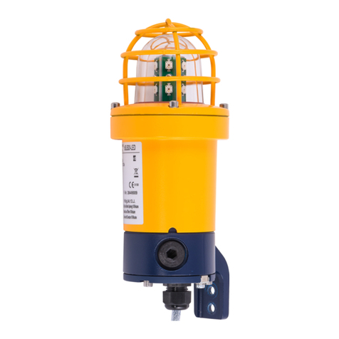
Eaton XB10 User manual

Technical manual
Xenon beacon - XB10

ii Xenon beacon - Xb10 TM102.L May 2022 www.eaton.com
DISCLAIMER OF WARRANTIES AND LIMITATION OF LIABILITY
The information, recommendations, descriptions and safety notations in this document are based on Eaton Corporation’s
(“Eaton”) experience and judgment and may not cover all contingencies. If further information is required, an Eaton sales
office should be consulted. Sale of the product shown in this literature is subject to the terms and conditions outlined in
appropriate Eaton selling policies or other contractual agreement between Eaton and the purchaser.
THERE ARE NO UNDERSTANDINGS, AGREEMENTS, WARRANTIES, EXPRESSED OR IMPLIED, INCLUDING
WARRANTIES OF FITNESS FOR A PARTICULAR PURPOSE OR MERCHANTABILITY, OTHER THAN THOSE
SPECIFICALLY SET OUT IN ANY EXISTING CONTRACT BETWEEN THE PARTIES. ANY SUCH CONTRACT STATES THE
ENTIRE OBLIGATION OF EATON. THE CONTENTS OF THIS DOCUMENT SHALL NOT BECOME PART OF OR MODIFY
ANY CONTRACT BETWEEN THE PARTIES.
In no event will Eaton be responsible to the purchaser or user in contract, in tort (including negligence), strict liability or
other-wise for any special, indirect, incidental or consequential damage or loss whatsoever, including but not limited to
damage or loss of use of equipment, plant or power system, cost of capital, loss of power, additional expenses in the
use of existing power facilities, or claims against the purchaser or user by its customers resulting from the use of the
information, recommendations and descriptions contained herein. The information contained in this manual is subject to
change without notice.

iii
Xenon beacon - XB10
English
Xenon beacon - Xb10 TM102.L May 2022 www.eaton.com
Contents
1.0 INTRODUCTION........................1
2.0 INSTALLATION................................................1
General ..........................................................1
Cable termination ..................................................1
General ..........................................................1
Exd unit ..........................................................1
Exde unit .........................................................1
3.0 OPERATION .........................................................................2
4.0 MAINTENANCE ......................................................................2
Removing/replacing xenon tube ................................................................ 2
5.0 CERTIFICATION/APPROVALS ...........................................................3
lECEx units ................................................................................ 3
ATEX units ................................................................................. 3
6.0 SPECIAL CONDITIONS FOR SAFE USE...................................................3
These units also have the following approvals ..................................................... 3

iv Xenon beacon - Xb10 TM102.L May 2022 www.eaton.com

1
Xenon beacon - XB10
English
Xenon beacon - Xb10 TM102.L May 2022 www.eaton.com
1.0 Introduction
These compact and lightweight 10 & 15 joule beacons
have been designed for use in potentially explosive
atmospheres and harsh environmental conditions.
The beacon housing, including the flamepaths, is
manufactured completely from a UV stable glass
reinforced polyester which is ideally suited for use
offshore and onshore, where light weight combined with
corrosion resistance is required.
Stainless steel screws and mounting bracket are
incorporated ensuring a totally corrosion free unit.
Anadditional body clamp is available for high
vibrationenvironments.
2.0 Installation
General
When installing and operating explosion-protected
equipment, requirements for selection, installation
and operation should be referred to e.g. IEEWiring
Regulations and the ‘National Electrical Code’ in North
America. Additional national and/or local requirements
may apply.
Ensure that all nuts, bolts and fixings are secure.
Ensure that only the correct listed or certified stopping
plugs are used to blank off unused gland entry points and
that the NEMA/IP rating of the unit is maintained. MEDC
recommend the use of a sealing compound such as
HYLOMAR PL32 on the threads of glands and stopping
plugs in order to maintain the IP rating of the unit.
The beacon is mounted via the 3 off Ø9mm mounting
holes in the standard L-shaped bracket fixed to the base of
the unit. The holes have been designed to accept an M8
screw or bolt.
MEDC recommend the use of stainless steel fixings.
Note that if the beacon is to be used in high amplitude
vibration applications, a secondary restraint would be
advisable. Please contact MEDC for details.
Cable termination
CAUTION: Before removing the cover assembly,
ensure that the power to the unit is isolated.
General
Cable termination should be in accordance with
specifications applying to the required application. MEDC
recommends that all cables and cores should be correctly
identified. Please refer to the wiring diagram provided
with the product.
Ensure that only the correct listed or certified cable
glands are used and that the assembly is shrouded and
correctlyearthed.
All cable glands should be of an equivalent NEMA/IP
rating to that of the beacon and integrated with the unit
such that this rating is maintained.
The internal earth terminal, where fitted, must be used
for the equipment grounding connection and the external
terminal is for a supplementary bonding connection
where local codes or authorities permit or require such
aconnection.
Ensure there is not too much slack of cable cores within
the unit due to space limitations.
Exd unit
Unscrew the set screw in the cover assembly one full
turn (2.0mm A/F hexagon key). Carefully unscrew and
remove the cover assembly (using a 120mm hook wrench
if required). Once the cover assembly has been removed,
slide the PCB assembly out of the unit until the terminals
clear the enclosure body.
After cable termination has been completed, the PCB can
be fully inserted into the enclosure, ensuring the spacer
on the bottom of the PCB snaps into the retaining clip on
the boss inside the enclosure base. Be aware of correct
PCB orientation, illustrated by the label adhered to the
inside wall of the enclosure body.
To replace the cover, use the same procedure as above
but in reverse manner, ensuring the O-ring is in good
condition and fitted in the correct location at the top of
the cover threads. Ensure the cover is screwed down
tightly and that there is no damage to the thread surfaces
or mating faces of the cover and enclosure. There should
be a maximum gap of 0.2mm between the faces of the
cover and enclosure to ensure correct o-ring compression.
Exde unit
Unscrew and remove the 2 off M5 screws (4.0mm A/F
hexagon key) and lift the Exe cover away from the base of
the unit.
Terminate the field wiring as shown on the wiring diagram
supplied with the unit.
Not more than one single or multiple strand lead shall be
connected into either side of any terminal, unless multiple
conductors have been joined in a suitable manner, e.g.
two conductors into a single insulated crimped boot
laceferrule.
Leads connected to the terminals shall be insulated for
the appropriate voltage and this insulation shall extend to
within 1mm of the metal of the terminal throat.
All terminal screws, used and unused, shall be tightened
down to between 0.5Nm and 0.6Nm. Conductive
metalwork (inc. cable glands) must be a minimum of
5mm away from the terminals After cable termination
has been completed, replace the Exe cover onto the
enclosure, ensuring there is no damage to the mating
faces and that the O-ring is correctly seated in its groove
to maintain the IP rating of the unit. Replace and tighten
the 2 off M5 cover screws (4.0mm A/F hexagon key).
DONOT over tighten the cover screws as this may cause
damage to the unit.
To maintain the IP rating of the unit, the recommended
torque on the cover screws is between 2.5 – 3.0Nm.

2Xenon beacon - Xb10 TM102.L May 2022 www.eaton.com
Xenon beacon - XB10
English
3.0 Operation
The operating voltage of the unit is stated on the unit label. The beacon can be powered directly or initiated via a
telephone ringing signal, depending on electronic configuration supplied.
General arrangement
Ex de VERSION
Ex eCOVER SCREWS
2POSITIONS
58±2mm
Ø123.5±2mm
45°±0.5°
357±5mm
GLANDENTRY
2POSITIONS
84±2mm
85±2mm
50±2mm
35±1mm
17.5±1mm
FIXING HOLE
Ø4.5±1mm
3POSITIONS
299±4mm
227±2mm
Ø
122±2mm
95±2mm
37±1mm
DO NOTOVER-TIGHTENSCREWS
ExeT
ERMINAL CHAMBER
ExdVERSION
4.0 Maintenance
During the working life of the unit, it should require little
or no maintenance. GRP will resist attack by most acids,
alkalis and chemicals and is as resistant to concentrated
acids and alkalis as most metal products. However, if
abnormal or unusual environmental conditions occur due
to plant damage or accident etc., then visual inspection
is recommended. If the unit requires cleaning, then only
clean exterior with a damp cloth to avoid electro-static
charge build up.
The replacement of the xenon tube (see below) can be
carried out by competent site personnel. Other repairs
should be undertaken by returning the unit to MEDC.
If a unit fault should occur, then the unit can be repaired
by MEDC. All parts of the unit are replaceable. If
you acquired a significant quantity of units, then it is
recommended that spares are also made available.
Pleasediscuss your requirements with the Technical Sales
Engineers at MEDC.
During maintenance, if the cover/lens assembly grease
needs to be re-applied, a PFPE (Perfluoropolyether) based
grease such as Krytox GPL203 by DuPont or Perfluorolube
22/6 by Performance Fluids Ltd should be used, to
prevent damage to the O-ring.
Removing/replacing xenon tube
CAUTION: Before removing the cover assembly,
ensure that the power to the unit is isolated.
ote:N These units each contain two separate xenon tubes
which should both be replaced at the same time.
Unscrew the setscrew on the cover one full turn
(2.0mm A/F hexagon key). Carefully unscrew and
remove the cover assembly (using a 120mmhook
wrench if required).
Remove the old tubes by unscrewing the terminal block
fixings. The replacement xenon tubes can now be fitted
(see the xenon tube installation sheet, which is supplied
with the replacement tube).
To replace the cover, use the same procedure as above
but in reverse manner, ensuring the cover is screwed
down tightly and ensuring there is no damage to
the thread surfaces or mating faces of the cover and
enclosure. There should be a maximum gap of 0.2mm
between the faces of the cover and enclosure to ensure
correct o-ring compression and maintain the IP rating of
the unit.

3Xenon beacon - Xb10 TM102.L May 2022 www.eaton.com
Xenon beacon - XB10
English
5.0 Certication/approvals
IECEx units
Ex d unit (IEC certification No. IECEx BAS 10.0086X)
10J:- Ex d IIB T4 (-55°C to +65°C) Gb
15J:- Ex d IIB T4 (-55°C to +50°C) Gb
Ex de unit (IEC certification No. IECEx BAS 10.0087X)
10J: Ex db eb IIB T4 (-50°C to +65°C) Gb
15J: Ex db eb IIB T4 (-50°C to +50°C) Gb
The IECEx certificate and product label carry the IECEx
equipment protection level marking
Gb
Where Gb signifies suitability for use in a Zone 1 surface
industries area in the presence of gas.
ATEX units
Ex d unit (ATEX certification No. BAS00ATEX2204X)
10J:- Ex d IIB T4 (-55°C to +65°C) Gb
15J:- Ex d IIB T4 (-55°C to +50°C) Gb
Ex de unit (ATEX certification No. BAS00ATEX2226X)
10J: Ex db eb IIB T4 (-50°C to +65°C) Gb
15J: Ex db eb IIB T4 (-50°C to +50°C) Gb
The ATEX certificate and product label carry the ATEX
group and category marking:
II 2 G
Where:
Signifies compliance with ATEX
II Signifies suitability for use in surface industries
2 Signifies suitability for use in a zone 1 area
G Signifies suitability for use in the presence of gases
6.0 Special conditions for safe use
A. Exd units: Certificates BAS00ATEX2204X & IECEx
BAS 10.0086X
I. The mating thread of any cable entry device unused
with this apparatus must exceed 12mm in length.
II. Painting and surface finishes, other than those
applied by the manufacturer, are not permitted.
B. Exde units: Certificates BAS00ATEX2226X & IECEx
BAS 10.0087X
I. Not more than one single or multiple strand lead shall
be connected into either side of any terminal, unless
multiple connectors have been joined in a suitable
manner, e.g. two conductors into a single insulated
crimped boot lace ferrule.
II. Leads connected to the terminal shall be insulated
for the appropriate voltage and this insulation shall
extend to within 1mm of the metal of the terminal
throat.
III. All terminal screws, used and unused, shall be fully
tightened down.
IV. Minimum creepage and clearance distances between
the terminals and adjacent conductive parts (including
cable entry devices) must be at least 5mm.
V. Painting and surface finishes, other than those
applied by the manufacturer, are not permitted.
These units also have the following approvals
Main Harmonics (AC) to EN61000-6-3:2007/
IEC61000-3-2:2006
Conducted Emissions (DC) to EN61000-6-3:2007
Radiated Field Immunity (DC and AC) to EN61000-6-
2:2005/IEC61000-4-3:2002 + A1:2002
Electrical Fast Transients/Bursts (DC and AC) to
EN61000-6-2:2005/IEC61000-4-4:2004
Dips and Interruptions (AC) to EN61000-6-2:2005/
IEC61000-4-11:2004
Ingress protection IP66 to BS EN 60529:1992
Ingress protection IP67 to BS EN 60529:2001

4
Xenon beacon - XB10
Francais
Xenon beacon - Xb10 TM102.L May 2022 www.eaton.com
Contents
1.0 INTRODUCTION........................5
2.0 INSTALLATION................................................5
Généralités .......................................................5
Connexion des câbles ...............................................5
Généralités .......................................................5
Unité Exd.........................................................5
Unité Ex de .......................................................5
3.0 FONCTIONNEMENT ..................................................................6
4.0 MAINTENANCE ......................................................................6
Retirer/remplacer le tube xénon ................................................................ 6
5.0 CERTIFICATION/HOMOLOGATIONS .....................................................7
Unités IECEx ............................................................................... 7
Unités ATEX................................................................................ 7
6.0 CONDITIONS SPÉCIALES POUR UNE UTILISATION EN TOUTE SÉCURITÉ .....................7
Ces unités disposent également des conformités suivantes .......................................... 7

5
Xenon beacon - XB10
Francais
Xenon beacon - Xb10 TM102.L May 2022 www.eaton.com
1.0 Introduction
Ces feux légers et compact 10 et 15 joules ont été conçus
pour pouvoir être utilisés en milieux potentiellement
explosifs et dans des conditions environnementales
difficiles. Le boîtier du feu et les chemins de flammes
sont fabriqués dans un polyester en verre traité anti-UV,
stable et renforcé, idéalement conçu pour la mer comme
la terre, lorsque des qualités de légèreté, de résistance à
la corrosion sont impératives.
Les vis en acier inoxydable et le support de fixation
préviennent entièrement d’une quelconque corrosion de
l’unité. Une pince d’ensemble supplémentaire est fournie
pour faire face aux environnements à fortes vibrations.
2.0 Installation
Généralités
Pour toute installation et mise en oeuvre d’un équipement
électrique antidéflagrant, la réglementation applicable,
comme celle sur les installations électriques de l’IEE
Wiring Regulations (réglementation IEE du câblage) et le
National Electrical Code (« code électrique national »), doit
être respectée. D’autres règlementations nationales et/ou
locales sont susceptibles de s’appliquer.
Vérifiez que les écrous, boulons et fixations sont
correctement serrés.
Veillez à obturer les points d’entrée non utilisés à l’aide
de bouchons certifiés du type approprié et prenez soin
de maintenir le niveau de classification NEMA/IP de
l’unité. Afin de maintenir le niveau de classification
NEMA/IP, MEDC recommande d’enduire le filetage des
presse-étoupes et des bouchons d’une pâte d’étanchéité
(HYLOMAR PL32, par exemple).
Le feu est monté au moyen des 3 orifices de fixation de
Ø9mm de diamètre du support standard en forme de L
situé à la base de l’unité. Ces orifices peuvent recevoir
une vis ou un boulon de type M8.
MEDC recommande d’utiliser des fixations en
acierinoxydable.
Nous recommandons une seconde fixation si le feu venait
à supporter des vibrations de grande amplitude. Veuillez
contacter MEDC pour plus d’informations.
Connexion des câbles
ATTENTION : Avant de déposer le couvercle, vérifiez
que l’unité est hors circuit.
Généralités
La connexion des câbles doit être conforme aux
spécifications pertinentes au vu de l’application. MEDC
recommande d’identifier clairement tous les câbles et
conducteurs. Veuillez vous reporter au schéma de câblage
fourni avec le produit.
Veillez à utiliser des presse-étoupes certifiés du type
approprié et vérifiez que l’ensemble est protégé et
correctement mis à la terre.
Tous les presse-étoupes doivent présenter un indice
NEMA/IP équivalent à celui du feu et être intégrés à
l’unité de façon à assurer le maintien de sa classification.
La borne interne de mise à la terre doit être utilisée pour
mettre l’équipement à la terre. La borne externe est
destinée à une connexion de protection supplémentaire et
doit être utilisée lorsque la réglementation locale autorise
ou impose une telle connexion.
L’espace dans l’unité étant restreint, veillez à ne pas
laisser trop de jeu parmi les câbles et conducteurs.
Unité Exd
Dévissez d’un tour complet et retirez la vis du couvercle
(clé Allen 2,0mm). Dévissez et retirez doucement
le couvercle (au moyen d’une clé à ergot 120mm si
nécessaire). Faites ensuite glisser le circuit imprimé pour
le retirer de l’unité et libérer le boîtier des terminaux.
Une fois les raccordements effectuées, le circuit imprimé
peut être réinséré dans le boîtier en s’assurant qu’il soit
de nouveau clipsé à la base du boîtier. Le circuit imprimé
ayant un sens, pensez à vérifier l’étiquette correspondante
à l’intérieur du boîtier.
La même procédure inversée est utilisée pour remplacer
le couvercle, en veillant à ce que le joint torique soit
en bonne condition et correctement placé en haut des
filetages du couvercle. Prendre soin de serrer fermement
le couvercle en veillant à ne pas abîmer les surfaces de
filetages et de contact du couvercle et du boîtier. Vérifiez
que l’écartement entre les faces du couvercle et le boîtier
ne dépasse pas un maximum de 0,2mm pour conserver
une bonne compression du joint torique.
Unité Ex de
Dévissez et retirer les deux vis M5 (clé Allen 4,0mm A/F)
et ôter le couvercle Exe de la base de l’unité Terminez les
raccordements en suivant le schéma de câblage fourni
avec l’unité.
Un seul brin ou brin multiple de plomb doit être connecté
au terminal sans la présence appropriée de plusieurs
conducteurs, par ex. deux conducteurs dans une cosse
sertie isolée.
Tous les câbles connectés aux terminaux doivent être
isolés à la tension appropriée sans toutefois s’écarter de
plus d’1mm du métal du terminal.
Toutes les vis de serrage, utilisées ou non, doivent être
resserrées à 0,5 – 0,6 Nm.
Tout métal conducteur (dont presse-étoupes) doit être
gardé à plus de 5mm des terminaux.
Une fois les raccordements effectués, remettez
soigneusement le couvercle Exe sur le boîtier, en veillant
à ne pas abîmer les surfaces de contact et en vérifiant
que le joint torique soit parfaitement positionné dans
son logement pour maintenir l’indice de protection IP.
Resserrez à fond les deux vis M5 du couvercle (clé Allen
4,0mm A/F). NE serrez PAS les vis du couvercle plus qu’il
n’est nécessaire sous peine d’endommager l’unité.
Pour maintenir l’indice de protection de l’appareil, le
couple de serrage recommandé pour les vis du couvercle
est de 2,5 – 3,0 Nm.
6Xenon beacon - Xb10 TM102.L May 2022 www.eaton.com
Xenon beacon - XB10
Francais
3.0 Fonctionnement
La tension d’alimentation de l’unité est indiquée sur l’étiquette. En fonction de la configuration électronique, le feu peut
être directement alimenté ou initié par téléphone.
Schéma general
VERSION Ex de
VisdecouverclesExe
2POSITIONS
58±2mm
Ø123,5±2mm
45°±0,5°
357±5mm
ENTRÉE DE
PRESSE-ÉTOUPE
2POSITIONS 84±2mm
85±2mm
50±2mm
35±1mm
17,5±1mm
TROUSDEFIXATION
Ø4,5±1mm
3POSITIONS
299±4mm
227±2mm
122±2m
m
95±2mm
37±1mm
NE PASTROPSERRERLES VIS
CHAMBRE DE BORNEExe
VERSION Ex d
4.0 Maintenance
Durant toute sa durée de vie, l’unité ne nécessite aucune
ou peu de maintenance. Le GRP sera non seulement
résistant aux acides, alcalis et composants chimiques
mais également aux mêmes acides concentrés et alcalis
que la plupart des produits métalliques.
Toutefois, lorsque les conditions environnementales
peuvent avoir un effet sur l’équipement (machine
endommagée, accident, etc.), il est recommandé de
procéder à une inspection visuelle.
Si un nettoyage s’avère nécessaire, veillez à nettoyer
uniquement l’extérieur avec un chiffon légèrement
humide afin d’éviter l’accumulation d’électricité statique.
Le remplacement du tube xenon (voir ci-dessous) peut
être effectué par un technicien compétent local. Pour les
autres réparations, l’unité doit être renvoyée à MEDC.
En cas de défaillance de l’équipement, celui-ci peut être
réparé par MEDC. Toutes les pièces sont remplaçables.
Lorsqu’un nombre significatif d’unités ont été acquises,
ilest recommandé de disposer d’unités de rechange. Les
technico-commerciaux de MEDC sont à la disposition
de la clientèle pour toute étude des besoins. Pendant
l’entretien, si la graisse d’assemblage couvercle/
lentille doit être ré-appliquée, une graisse de type PFPE
(perfluoropolyéther) comme la Krytox GPL203 de DuPont
ou Perfluorolube 22/6 de Performance Fluids Ltd doivent
être utilisées afin d’éviter d’endommager le joint torique.
Retirer/remplacer le tube xénon
ATTENTION : Avant de déposer le couvercle, vérifiez
que l’unité est hors circuit.
Remarque : Certaines unités sont pourvues de deux
tubes xénon distincts qui doivent être
remplacés concomitamment.
Dévissez d’un tour complet et retirez la vis du couvercle
(clé Allen 2,0mm). Dévissez et retirez doucement
le couvercle (au moyen d’une clé à ergot 120mm
sinécessaire).
Retirez doucement les tubes en dévissant les fixations
du terminal. Vous pouvez maintenant déposer les tubes
xénon de rechange (consultez la notice d’installation du
tube xénon fourni avec le tube de rechange). Lamême
procédure inversée est utilisée pour remplacer le
couvercle, en veillant à serrer fermement le couvercle
sans abîmer les surfaces de filetages et de contact du
couvercle et du boîtier. Vérifiez que l’écartement entre
les faces du couvercle et le boîtier ne dépasse pas
un maximum de 0,2mm pour conserver une bonne
compression du joint torique et maintenir le niveau de
classification IP de l’unité.

7Xenon beacon - Xb10 TM102.L May 2022 www.eaton.com
Xenon beacon - XB10
Francais
5.0 Certications/homologations
Unités IECEx
Unité Ex d (certification IEC n° IECEx BAS 10.0086X)
10J : - Ex d IIB T4 (de -55 °C à +65 °C) Gb
15J : - Ex d IIB T4 (de -55 °C à +50 °C) Gb
Unité Ex de (certification IEC n° IECEx BAS 10.0087X)
10J: Ex db eb IIB T4 (de -50°C à +65°C) Gb
15J: Ex db eb IIB T4 (de -50°C à +50°C) Gb
Le certificat IECEx et l’étiquette du produit portent le
niveau de protection du matériel de marquage IECEx
Gb
Où Gb signifie que l’équipement est adapté à une
utilisation dans les industries de surface, en zone 1,
enprésence du gaz.
Unités ATEX
Unité Ex d (certification ATEX n° BAS00ATEX2204X)
10J : - Ex d IIB T4 (de -55 °C à +65 °C) Gb
15J : - Ex d IIB T4 (de -55 °C à +50 °C) Gb
Unité Ex de (certification ATEX n° BAS00ATEX2226X)
10J: Ex db eb IIB T4 (de -50°C à +65°C) Gb
15J: Ex db eb IIB T4 (de -50°C à +50°C) Gb
Le certificat ATEX et l’étiquette du produit portent le
groupe ATEX et la catégorie de marquage :
II 2 G
Où :
Signifie que l’équipement est conforme à la
règlementation ATEX
II Signifie que l’équipement est adapté à une
utilisation dans les industries de surface
2 Signifie que l’équipement est adapté à une
utilisation en zone 1
G Signifie que l’équipement est adapté à une
utilisation en présence de gaz
6.0 Conditions spéciales pour une
utilisation en toute sécurité
A. Unités Exd : Certificats BAS00ATEX2204X & IECEx
BAS 10.0086X
I. Le filtetage de contact de tout périphérique d’entrée
de câble inutilisé avec cette appareil doit mesurer
plus de 12mm.
II. Toutes peintures ou finitions de surface autres
que celles appliquées par le fabricant ne sont pas
autorisées.
B. Unités Exde : Certificats BAS00ATEX2226X & IECEx
BAS 10.0087X
I. Un seul brin ou brin multiple de plomb doit être
connecté au terminal sans la présence appropriée
de plusieurs connecteurs, par ex. deux conducteurs
dans une cosse sertie isolée.
II. Tous les câbles connectés au terminal doivent être
isolés à la tension appropriée sans toutefois s’écarter
de plus d’1mm du métal du terminal.
III. Qu’elles soit utilisées ou non, toutes les vis du
terminal doivent être serrées à fond.
IV. Le cheminement minimum et la distance requise
entre les terminaux et les pièces conductrices
adjacentes (dont les périphériques d’entrée de câble)
doivent être supérieurs à 5mm.
V. Toutes peintures ou finitions de surface autres
que celles appliquées par le fabricant ne sont
pasautorisées.
Ces unités disposent également des
conformités suivantes
Harmoniques principales (CA) EN61000-6-3:2007/
IEC61000-3-2:2006
Émissions conduites (CC) EN61000-6-3:2007
Immunité aux champs rayonnés (CC et CA) EN61000-6-2:
2005/IEC61000-4-3:2002 + A1:2002
Immunité aux décharges transitoires électriques rapides
(CC et CA) EN61000-6-2:2005/IEC61000-4-4:2004
Creux et interruption (CA) EN61000-6-2:2005/
IEC61000-4-11:2004
Ingress protection (IP66) BS EN 60529:1992
Ingress protection (IP67) BS EN 60529:2001

8
Xenon beacon - XB10
Deutsch
Xenon beacon - Xb10 TM102.L May 2022 www.eaton.com
Contents
1.0 EINLEITUNG...........................9
2.0 INSTALLATION................................................9
Allgemeines.......................................................9
Kabelenden .......................................................9
Allgemeines.......................................................9
Exd-gerät .........................................................9
Exde-gerät ........................................................9
3.0 BETRIEB ...........................................................................10
4.0 WARTUNG .........................................................................10
Entfernung/Erneuerung der Xenon-Röhren ....................................................... 10
5.0 ZERTIFIZIERUNG/GENEHMIGUNGEN...................................................11
Iecex einheiten .............................................................................11
ATEX Einheiten .............................................................................11
6.0 SPEZIELLE BEDINGUNGEN FÜR DIE SICHERE VERWENDUNG..............................11
Diese Geräte besitzen auch die folgenden Genehmigungen ..........................................11

9
Xenon beacon - XB10
Deutsch
Xenon beacon - Xb10 TM102.L May 2022 www.eaton.com
1.0 Einleitung
Diese leichten, kompakten 10 & 15 Joule Signalleuchten
sind für den Einsatz in explosionsgefährdeten Bereichen
und erschwerten Umgebungsbedingungen ausgelegt.
Das Gehäuse, einschließlich Flammenpfad, ist komplett
aus mit Glasfaser verstärktem, UV-beständigen Polyester
gefertigt und eignet sich sowohl für den Einsatz an Land
als auch auf See, wenn geringes Gewicht und hohe
Korrosionsbeständigkeit erforderlich sind.
Verschraubungen und Befestigungsbügel aus Edelstahl
gewährleisten einen vollständigen Korrosionsschutz.
Eine zusätzliche Gehäuseklammer ist für den Einsatz in
starkvibrationsgefährdeter Umgebung erhältlich.
2.0 Installation
Allgemeines
Bei Installation und Betrieb explosionsgeschützter
Komponenten finden Sie Informationen zu den
Anforderungen für Auswahl, Installation und
Betrieb z. B. in Nordamerika in den EE Wiring
Regulations (Verdrahtungsrichtlinien der IEE) und im
“National Electrical Code“ (Sicherheitsstandard für
Elektroinstallationen). Möglicherweise gelten weitere
lokale und/oder nationale Bestimmungen.
Stellen Sie sicher, dass alle Muttern, Schrauben und
Befestigungen gesichert sind.
Stellen Sie sicher, dass nur die richtigen oder
zertifizierten Stopfen verwendet werden, um ungenutzte
Eingangspunkte zu verschließen und dass die NEMA/
IP-Einstufung der Einheit erhalten bleibt. MEDC empfiehlt
den Einsatz eines Dichtmittels, wie z. B. HYLOMAR PL32,
an den Gewinden der Durchführungen und Stopfen, um
die IP-Einstufung der Einheit zu erhalten.
Die Blitzleuchte ist mit drei Durchgangsbohrungen mit
Ø9mm über den standardmäßige L-förmigen Bügel am
Sockel des Geräts angebracht. Die Öffnungen wurden für
eine M8-Schraube oder einen Bolzen konzipiert.
MEDC empfiehlt die Verwendung von
Befestigungselementen aus Edelstahl.
Bitte beachten Sie, dass bei einer Verwendung der
Blitzleuchte für Anwendungen mit Schwingungen
hoher Amplitude der Einsatz einer zweiten
schwingungsdämpfenden Klammer ratsam ist.
Bitte kontaktieren Sie MEDC, um Genaueres hierzu
zuerfahren.
Kabelenden
ACHTUNG: Stellen Sie vor dem Abnehmen der
Abdeckungseinheit sicher, dass der Energiefluss durch
die Einheit isoliert ist.
Allgemeines
Die Terminierung der Kabel muss entsprechend der
Anforderungen der jeweiligen Anwendung erfolgen.
MEDC empfiehlt die korrekte Identifizierung aller Kabel
und Kerne. Informationen hierzu finden Sie im Schaltplan
des Produkts.
Stellen Sie sicher, dass nur die richtig gelisteten oder
zertifizierten Kabeldurchführungen verwendet werden und
dass die Baugruppe korrekt verkleidet und geerdet ist.
Alle Kabeldurchführungen müssen über eine NEMA/
IP-Einstufung verfügen, die der des Blinklichts entspricht
und in die Einheit integriert ist, sodass diese Einstufung
erhalten bleibt.
Die interne Erdungsklemme (sofern vorhanden) muss
für den Erdungsanschluss der Komponente verwendet
werden. Die externe Klemme ist für eine zusätzliche
Verbindung vorgesehen, sofern lokale Vorschriften oder
Behörden eine solche Verbindung zulassen.
Sorgen Sie dafür, dass die Kabeladern im Gerät nicht zu
viel überschüssige Länge haben, da der Platz begrenzt ist.
Exd-gerät
Lösen Sie die Feststellschraube an der Abdeckung eine
volle Drehung (2,0mm AF-Sechskantschlüssel). Lösen und
entfernen Sie die Abdeckung vorsichtig (wenn erforderlich
mit einem 120mm Hakenschlüssel). Ziehen Sie nach
Entfernung der Abdeckung die Platine so weit aus dem
Gerät heraus, dass die Klemmen frei vom Gehäuse sind.
Nach Fertigstellung des Kabelabschlusses kann die
Platine vollständig in das Gehäuse eingeschoben werden,
wobei darauf zu achten ist, dass der Distanzhalter auf der
Unterseite der Platine im Halteclip am Vorsprung auf der
Gehäuseinnenseite einrastet. Achten Sie auf die richtige
Ausrichtung der Platine, die auf dem Etikett auf der
Innenwand des Gehäuses nachgeprüft werden kann.
Zur Wiederanbringung des Deckels verwenden Sie
dasselbe Verfahren in umgekehrter Reihenfolge und
stellen Sie sicher, dass sich der O-Ring in einem guten
Zustand befindet und an der korrekten Position an den
Gewinden der Abdeckung angebracht ist. Stellen Sie
sicher, dass der Deckel fest angeschraubt ist und die
Gewindeoberflächen an den Kontaktstellen der Abdeckung
und des Gehäuses keine Schäden aufweisen. Zwischen
den Stirnflächen des Gehäuses und des Deckels sollte ein
Abstand von 0,2mm sein, um zu gewährleisten, dass der
O-Ring korrekt zusammengedrückt wird.
Exde-gerät
Lösen Sie die zwei M5-Schrauben (4,0mm
A/F-Sechskantschlüssel) und heben Sie die Exe-Abdeckung
vom Sockel des Geräts ab.
Schließen Sie die Feldverdrahtung wie im mitgelieferten
Schaltplan ab.
Höchstens eine Einleiter- oder Vieldrahtlitzenleitung ist
auf einer der beiden Klemmenseiten anzuschließen, es
sei denn mehrere Leiter wurden auf geeignete Weise
zusammengeführt, z.B. zwei Leiter in einer isolierten
Doppelader-Quetschhülse.
Die an die Klemmen angeschlossenen Leitungen müssen
für die jeweilige Spannung ausreichend isoliert sein, und
diese Isolierung muss sich bis innerhalb eines Millimeters
vor dem Metall des Klemmenhalses erstrecken Alle
gebruikte en ongebruikte schroefklemmen, moeten
worden vastgedraaid tussen 0,5Nm en 0,6Nm. Leitende
Metallteile (einschl. Kabeldurchführungen) müssen
mindestens 5mm Abstand von den Klemmen haben

10 Xenon beacon - Xb10 TM102.L May 2022 www.eaton.com
Xenon beacon - XB10
Deutsch
Nach Fertigstellung des Kabelanschlusses setzten Sie
die Abdeckung wieder auf das Gehäuse. Stellen Sie
sicher, dass die Kontaktstellen nicht beschädigt sind,
und dass der O-Ring ordnungsgemäß in der Nut sitzt,
damit die korrekte IP-Klasse erhalten bleibt. Ziehen
Sie die zwei M5-Schrauben der Abdeckung (4,0mm
A/F-Sechskantschlüssel) wieder fest. Ziehen Sie die
Schrauben an der Abdeckung NICHT ZU FEST an, da dies
Schäden am Gerät zur Folge haben kann.
Voor het handhaven van de IP-classificatie van de
unit, is de aanbevolen koppel op de afdekschroeven
tussen 2,5 – 3,0Nm.
3.0 Betrieb
Die Betriebsspannung der Einheit wird auf dem Typenschild angegeben. Die Xenon-Blitzleuchte kann abhängig von der
gelieferten Elektronikkonfiguration direkt angetrieben oder über ein Telefon-Rufzeichen aktiviert werden.
Aufbau
Ex de-VERSION
Ex e-ABDECKSCHRAUBEN
2STELLEN
58±2mm
Ø123,5±2mm
45°±0,5°
357±5mm
KABELEINFÜHRUNG
2STELLEN 84±2mm
85±2mm
50±2mm
35±1mm
17,5±1mm
BEFESTIGUNGSBOHRUNG
Ø4,5±1mm
3STELLEN
299±4mm
227±2mm
1
22±2mm
95±2mm
37±1mm
NICHT ZUFEST ANZIEHEN
Exe-ANSCHLUSSKASTEN
SCHRAUBEN
Ex d-VERSION
4.0 Wartung
Die Einheit benötigt im Nutzungszeitraum kaum oder gar
keine Wartung. Glasfaserverstärkter Kunststoff hält den
Angriffen der meisten Säuren, Alkalien und Chemikalien
stand und ist wie die meisten Metalle widerstandsfähig
gegenüber konzentrierter Säuren und Alkalien.
Sollte es aufgrund von Anlagenschäden, Unfällen
etc. zu unnormalen oder ungewöhnlichen
Umgebungsbedingungen kommen, wird eine
Sichtprüfungempfohlen.
Muss die Einheit gereinigt werden, reinigen Sie nur die
Außenseite mit einem feuchten Tuch, um elektrostatische
Aufladung zu vermeiden.
Der Austausch der Xenon-Röhren kann durch
kompetentes Personal vor Ort erfolgen (siehe unten).
Weitere Reparaturen erfordern die Einsendung der Einheit
an MEDC.
Tritt ein Fehler auf, kann die Einheit von MEDC repariert
werden. Alle Teile der Einheit sind austauschbar. Wenn Sie
eine größere Stückzahl dieser Einheit erworben haben,
wird empfohlen, auch Ersatzteile bereitzustellen.
Besprechen Sie Ihre Anforderungen mit den technischen
Vertriebsmitarbeitern von MEDC.
Falls bei Wartungsarbeiten die Schmierung der
Abdeckungs-/Linsenbaugruppe erneuert werden muss,
ist ein Schmiermittel auf PFPE (Perfluorpolyether)-Basis
wie z. B. Krytox GPL203 von DuPont oder Perfluorolube
22/6 von Performance Fluids Ltd zu verwenden, um eine
Beschädigung des O-Rings zu vermeiden.
Entfernung/Erneuerung der Xenon-Röhren
ACHTUNG: Stellen Sie vor dem Abnehmen der
Abdeckungseinheit sicher, dass der Energiefluss durch
die Einheit isoliert ist.

11Xenon beacon - Xb10 TM102.L May 2022 www.eaton.com
Xenon beacon - XB10
Deutsch
Hinweis: Diese Geräte enthalten jeweils zwei separate
Xenon-Röhren. Es wird empfohlen, alle Röhren
gleichzeitig auszutauschen.
Lösen Sie die Feststellschraube an der Abdeckung eine
volle Drehung (2,0mm AF-Sechskantschlüssel). Lösen und
entfernen Sie die Abdeckung vorsichtig (wenn erforderlich
mit einem 120mm Hakenschlüssel). Entfernen Sie die
alten Röhren, indem Sie die Klemmenblockbefestigungen
lösen. Die neuen Xenon-Röhren können nun angebracht
werden (siehe Installationsanleitung für die Xenon-Röhren,
welche zusammen mit der Ersatzröhre geliefert wird).
Zur Wiederanbringung des Deckels verwenden Sie
dasselbe Verfahren in umgekehrter Reihenfolge
und stellen Sie sicher, dass der Deckel fest
angeschraubt ist. Stellen Sie außerdem sicher, dass die
Gewindeoberflächen an den Kontaktstellen der Abdeckung
und des Gehäuses keinen Schaden aufweisen. Zwischen
den Stirnflächen des Gehäuses und des Deckels sollte ein
Abstand von 0,2mm sein, um zu gewährleisten, dass der
O-Ring korrekt zusammengedrückt wird und der IP-Wert
der Einheit erhalten wird.
5.0 Zertizierung/genehmigungen
IECEx-einheiten
Ex d-Einheit (IEC-Zertifizierungs-Nr. IECEx BAS 10.0086X)
10J:- Ex d IIB T4 (-55°C bis +65°C) Gb
15J:- Ex d IIB T4 (-55°C bis +50°C) Gb
Ex de-Einheit (IEC-Zertifizierungs-Nr. IECEx BAS 10.0087X)
10J: Ex db eb IIB T4 (-50°C bis +65°C) Gb
15J: Ex db eb IIB T4 (-50°C bis +50°C) Gb
Das IECEx-Zertifikat und das Typenschild sind mit der
IECEx-Schutzstufe versehen
Gb
Gb steht für die Eignung in einem Oberflächenbereich der
Zone 1 bei Vorhandensein von Gas.
ATEX-einheiten
Ex d-Einheit (ATEX-Zertifizierungs-Nr. BAS00ATEX2204X)
10J:- Ex d IIB T4 (-55°C bis +65°C) Gb
15J:- Ex d IIB T4 (-55°C bis +50°C) Gb
Ex de-Einheit (ATEX-Zertifizierungs-Nr. BAS00ATEX2226X)
10J: Ex db eb IIB T4 (-50°C bis +65°C) Gb
15J: Ex db eb IIB T4 (-50°C bis +50°C) Gb
Das ATEX-Zertifikat und das Typenschild sind mit der
ATEX-Gruppe und der Kategorie-Kennzeichnung versehen:
II 2 G
Hierbei gilt:
Steht für die ATEX-Kompatibilität
II Steht für die Eignung in Oberflächenbranchen
2 Steht für die Eignung in einem Bereich der Zone 1
G Steht für die Eignung bei Vorhandensein von Gasen
6.0 Spezielle bedingungen für die sichere
verwendung
A. Exd-Einheiten: Zertifikate BAS00ATEX2204X & IECEx
BAS 10.0086X
I. Das im Eingriff befindliche Gewinde jeder mit diesem
Gerät verwendeten Kabeleinführungsvorrichtung
muss länger als 12mm sein.
II. Eine andere Lackierung oder Oberflächenbehandlung
als die bereits vom Hersteller gelieferte ist
nichtzulässig.
B. Exde-Einheiten: Zertifikate BAS00ATEX2226X & IECEx
BAS 10.0087X
I. Höchstens eine Einleiter- oder Vieldrahtlitzenleitung ist
auf einer der beiden Klemmenseiten anzuschließen,
es sei denn mehrere Leiter wurden auf geeignete
Weise zusammengeführt, z.B. zwei Leiter in einer
isolierten Doppelader-Quetschhülse.
II. Die an der Klemme angeschlossenen Leitungen
müssen für die jeweilige Spannung ausreichend
isoliert sein, und diese Isolierung muss sich bis
innerhalb eines Millimeters vor dem Metall des
Klemmenhalses erstrecken.
III. Alle Klemmenschrauben (benutzte und unbenutzte)
sind anzuziehen.
IV. Kriechstrecken und Sicherheitsabstände zwischen
den Klemmen und benachbarten leitenden Teilen (ein
schließlich Kabeleinführungsvorrichtungen) müssen
mindestens 5mm betragen.
V. Eine andere Lackierung oder Oberflächenbehandlung
als die bereits vom Hersteller gelieferte ist
nichtzulässig.
Diese Geräte besitzen auch die folgenden
Genehmigungen
Oberschwingungsemission (Wechselstrom) gemäß
EN61000-6-3:2007 / IEC61000-3-2:2006
Leitungsgebundene Störungsaussendungen (Gleichstrom)
gemäß EN61000-6-3:2007
Strahlungsfeldimmunität (Gleich- und Wechselstrom)
gemäß EN61000-6-2:2005 / IEC61000-4-3:2002 + A1:2002
Elektrische schnelle Transienten/Impulspakete
(Gleich- und Wechselstrom) gemäß EN61000-6-2:2005 /
IEC61000-4-4:2004
Spannungsschwankungen und -unterbrechungen
(Wechselstrom) gemäß EN61000-6-2:2005 /
IEC61000-4-11:2004
Schutzklasse IP66 gemäß BS EN 60529:1992
Schutzklasse IP67 gemäß BS EN 60529:2001

Eaton is a registered trademark.
All trademarks are property
of their respective owners.
Eaton
EMEA Headquarters
Route de la Longeraie 7
1110 Morges, Switzerland
Eaton.eu
© 2022 Eaton
All Rights Reserved
Publication No. TM102.L
May 2022
Changes to the products, to the information contained in this
document, and to prices are reserved; so are errors and omissions.
Only order confirmations and technical documentation by Eaton is
binding. Photos and pictures also do not warrant a specific layout or
functionality. Their use in whatever form is subject to prior approval
by Eaton. The same applies to Trademarks (especially Eaton, Moeller,
and Cutler-Hammer). The Terms and Conditions of Eaton apply, as
referenced on Eaton Internet pages and Eaton order confirmations.
Table of contents
Languages:
Other Eaton Security System manuals

Eaton
Eaton i-on30R+ User manual

Eaton
Eaton XB11 User manual

Eaton
Eaton Scantronic i-on10 User manual

Eaton
Eaton XB12 User manual

Eaton
Eaton 415-TF Manual

Eaton
Eaton Crouse-hinds series User manual

Eaton
Eaton i-on30R User manual

Eaton
Eaton Symphoni LX Base User manual

Eaton
Eaton TWIN LED User manual

Eaton
Eaton PH1 User manual

Eaton
Eaton i-on1000EX User manual

Eaton
Eaton i-on160EX User manual

Eaton
Eaton i-on16 User manual

Eaton
Eaton MENVIER30 User manual

Eaton
Eaton Crouse-hinds series User manual

Eaton
Eaton Menvier 20 User manual

Eaton
Eaton Funke+Huster Fernsig TWIN-EExll User manual

Eaton
Eaton 423-TF Manual

Eaton
Eaton BG User manual

Eaton
Eaton i-on40H+ User manual