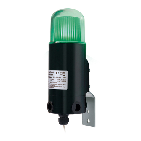
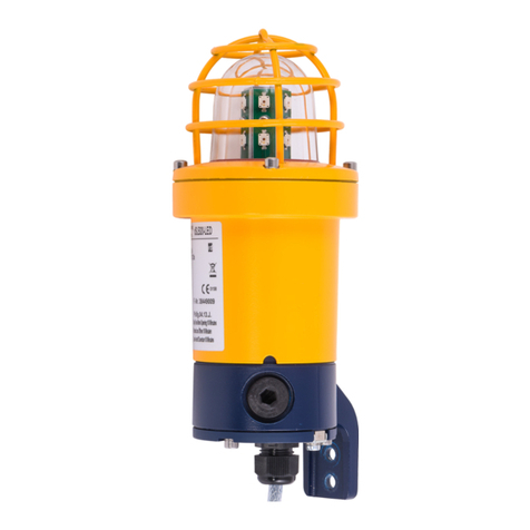
Eaton TWIN LED User manual

TWIN LED Technical Manual
Telefon Zweit- und Signalmelder/Secondary
telephone call and signal indicator TWIN LED

2
TWIN LED Technical Manual
TWIN LED TECHNICAL MANUAL TMF001 July 2019 www.eaton.com
TWIN LED Abmessungen/Dimensions
Hinweis
Vor Installation des Gerätes ist diese Gebrauchsanleitung
sorgfältig zu lesen. Bei eventuellen Schäden und Ansprü-
chen gelten die „Allgemeinen Lieferbedingungen für
Erzeugnisse und Leistungen der Elektroindustrie“ in ihrer
jeweils letzten Fassung.
Verwendungszweck
Der Telefon Zweit- und Signalmelder Typ TWIN LED ist
ein Gerät, das zum Anschluss an analoge, öffentliche Tele-
fonnetze und Nebenstellenanlagen vorgesehen ist. Beim
Empfang eines Tonrufsignals auf dem Telefonanschluss
sendet das Gerät optische und akustische Signale. Die
bestimmungsgemäße Gebrauchslage des Gerätes ist
beliebig.
Recycling
Die Komplettentsorgung der Geräte erfolgt über den
Elektronikabfall. Bei Demontage des Gerätes sind die
Komponenten Kunststoff, Metalle und Elektronik separat
zu entsorgen.
Note
Before installing the device, these instructions are to be
read carefully. In the event of any damages and claims,
the “General Terms of Delivery for Products and Services
of the Electrical Industry” shall apply in their respective
valid version.
Intended purpose
The secondary telephone call and signal indicator, TWIN
LED type, is a device intended for connection to analogue
public telephone networks and private extension systems.
When a tone call signal is received on the telephone
connection, the device sends optical and acoustic signals.
The position of normal use is unrestricted.
Recycling
The devices are disposed of entirely via electronic waste.
If a device is disassembled, the plastic, metal and elec-
tronics components are to be disposed of separately.
Anschlussraum / Terminal room
PA
TCP2
TCP1
PE
N / V-
L/ V+

3
TWIN LED Technical Manual
TWIN LED TECHNICAL MANUAL TMF001 July 2019 www.eaton.com
Montage
Der TWIN LED ist für die Wand- und Deckenmontage
geeignet. Die Anbaumaße sind dem Maßbild zu
entnehmen. Befestigungselemente und Untergrund
müssen das Gewicht des Gerätes tragen können.
Anschließen
Achtung: Zum Öffnen des Gerätes muss es spannungs-
frei geschaltet sein!
Das Anschließen und Einstellen des Gerätes darf nur
durch unterwiesenes Fachpersonal erfolgen. Es sind die
Vorschriften und Hinweise des jeweiligen Landes zum
Anschalten an das öffentliche Telefonnetz bzw. an private
Nebenstellenanlagen zu beachten. Die Klemmenbezeich-
nungen und zulässigen Spannungsversorgungen sind den
unten stehenden technischen Daten zu entnehmen.
Bei den werkseitig bestückten KLE ist die beigefügte
Betriebsanleitung zu beachten.
Hinweise zur Installation
Um zu verhindern, dass ein sich aus der
Anschlussklemme versehentlich gelöstes und nicht iso-
liertes Leitungsende, unkontrolliert Kontakt zu anderen
Bauteilen bekommt, muss es gesichert werden. Dazu
wird ein Kabelbinder je Anschlussleitung, in ca. 2,5cm
Abstand von der Anschlussklemme, fest um alle
Einzeladern gebunden.
Wahl der Betriebsarten
Telefonzweitmelder:
Für die Spannungsversorgung sind die Klemmen L
/ V+, N / V- und PE auf der rechten Seite im Gerät
vorgesehen. Für das Telefonnetz sind die Klemmen TCP1,
TCP2 auf der linken Seite im Gerät vorgesehen. Der
linke Kontakt im Schiebeschalter muss in der Position
„Telefonzweitmelder“ stehen (siehe „Einstellen des
Schiebeschalters“).
Signalmelder:
Für die Spannungsversorgung sind die Klemmen L
/ V+, N / V- und PE auf der rechten Seite im Gerät
vorgesehen. Der linke Kontakt im Schiebeschalter muss
in der Position „Signalmelder“ stehen (s. „Einstellen des
Schiebeschalters“).
Wahl der Melodie und der Lautstärke
Mit den drei rechten Kontakten des Schiebeschalters
lässt sich die Melodie und die Lautstärke des akustischen
Signales verändern (s. „Einstellen des Schiebeschalters“).
Einstellen des Schiebeschalters
Hinweis: In den Abbildungen Anschlussraum sind alle
Schieber in Stellung OFF. Die Position von Schieber 4 ist
der Schieber ganz links.
Einstellung Telefonzweitmelder: Schieber 4 = ON
Einstellung Signalmelder: Schieber 4 = OFF
Assembly
The TWIN LED is suitable for wall and ceiling assembly.
The mounting dimensions can be found on the dimen-
sional drawing. The fastening elements and the surface
beneath the device must be able to bear its weight.
Connection
Important: Power to the device must be switched off
before it is opened!
The connection and setting of the device may only be
carried out by instructed specialist personnel. The regu-
lations and instructions of the respective country for
connecting to the public telephone network or to private
extension systems are to be considered. The terminal
designations and permissible voltage supplies are shown
in the technical data below.
For the factory-assembled cable glands, the enclosed
operating instructions must be considered.
Installation instructions
Thus it is prevented, that one off the terminal block acci-
dentally loosened and non-isolated cable end, gets uncon-
trolled contact to other components, must it be backed
up. For this purpose, one cable tie is used per connection
cable, at a distance of about 2.5cm from the terminal
block. Fixed and tight bound to all single wires.
Selecting modes of operation
Secondary telephone call indicator:
The terminals L / V+, N / V- and PE in the device on the
right-hand side are provided for the voltage supply.
The terminals TCP1 and TCP2 in the device on the
left-hand side are provided for the telephone network.
The left-hand contact in the sliding switch must be in
the position “secondary telephone call indicator” (see
“Setting the sliding switch”).
Signal indicator:
The terminals L / V+, N / V- and PE in the device on
the right-hand side are provided for the voltage supply.
The left-hand contact in the sliding switch must be in
the position “signal indicator” (see “Setting the sliding
switch”).
Selecting the melody and volume
The melody and the volume of the acoustic signal can be
changed using the three right-hand contacts of the sliding
switch (see “Setting the sliding switch”).
Setting the sliding switch
Note: In the connection compartment illustrations, are
sliders are shown in OFF position. The position of slider 4
is the slider on the far left-hand side.
Setting of secondary telephone call indicator:
Slider 4 = ON
Setting of signal indicator: Slider 4 = OFF
CE-Zeichen
Wir erklären hiermit, dass sich dieses Produkt in Übereinstimmung mit den
grundlegenden Anforderungen und anderen relevanten Vorschriften der
EMV-Richtlinien 2014/30/EU, der Niederspannungsrichtlinien 2014/35/EU,
der Richtlinie 2006/25/EG (künstliche optische Strahlung) und der RoHS-
Richtlinie 2011/65/EU befindet.
Die entsprechenden Normen entnehmen Sie bitte den
Konformitätserklärungen auf unserer Website.
CE Marking
We hereby declare this product is in compliance with the essential
requirements and other relevant provisions of EMC Directive 2014/30/EU,
Low Voltage Directive 2014/35/EU, Directive 2006/25/EC (artificial optical
radiation) and RoHS Directive 2011/65/EU.
The appropriate standards you can take from the conformity declarations on
our Website.
4
TWIN LED Technical Manual
TWIN LED TECHNICAL MANUAL TMF001 July 2019 www.eaton.com
Schieber 1
Slider 1 Schieber 2
Slider 2 Schieber 3
Slider 3 Lautstärke
Volume Töne
Tones Tonfolge
Tone sequence ca. Lautstärke (dB(A) /1m)
approx. Volume (dB(A) /1m)
ON ON ON laut / loud 28,3 Hz 99
OFF ON ON laut / loud 225 Hz 101
ON OFF ON laut / loud 35,6 Hz 100
OFF OFF ON laut / loud 33,9 Hz 99
ON ON OFF leise / quiet 28,3 Hz 92
OFF ON OFF leise / quiet 225 Hz 91
ON OFF OFF leise / quiet 35,6 Hz 92
OFF OFF OFF leise / quiet 33,9 Hz 92
Technische Daten
Betriebsarten
Telefon Zweit- wahlweise Signalmelder Über Schiebeschalter wählbar
Telefon Zweitmelder Signalisierung erfolgt bei Anruf aus dem analogen Telefonnetz
– hierzu muss die Netzspannung anliegen
Signalmelder Signalisierung erfolgt nach Einschalten der Netzspannung
Anschlussdaten
Kabel- und Leitungseinführungen 2 Stück M20 x 1,5
Klemmvermögen 0,2 – 2,5 mm² Litze
0,2 – 4 mm² massiv
Netzanschluss
Klemmenbezeichnung Bei AC-Versorgung: L, N, PE, zusätzlich PA außen
Bei DC-Versorgung: V+, V-, PA außen
Spannungsversorgung AC Überspannungskategorie CAT II (gemäß EN60664-1)
115 - 230 V; 0,08 - 0,04 A; 50 - 60 Hz
Zulässige minimale Spannung = 100 VAC
Zulässige maximale Spannung = 253 VAC
Nominaldaten bei 230 VAC:
INS = 0,02 A (Ruhestrom)
IN= 0,042 A (Arbeitsstrom)
IICL = 0,4 APeak (Einschaltstoßstrom)
PN= 5 W (Wirkleistung)
SN= 8 VA (Scheinleistung)
λ= 0,62 (Leistungsfaktor)
Nominaldaten bei 115 VAC:
INS = 0,02 A (Ruhestrom)
IN= 0,084 A (Arbeitsstrom)
IICL = 0,4 APeak (Einschaltstoßstrom)
PN= 5 W (Wirkleistung)
SN= 9 VA (Scheinleistung)
λ= 0,62 (Leistungsfaktor)
Spannungsversorgung DC DC 24 V; 0,18 A
Zulässige minimale Spannung = 19,2 VDC
Zulässige maximale Spannung = 26,4 VDC
Nominaldaten bei 24 VDC:
INS = 0,06 A (Ruhestrom)
IN= 0,18 A (Arbeitsstrom)
IICL = 0,3 APeak (Einschaltstoßstrom)
PN= 4 W (Wirkleistung)
Betriebsdauer Für Dauerbetrieb geeignet

5
TWIN LED Technical Manual
TWIN LED TECHNICAL MANUAL TMF001 July 2019 www.eaton.com
Technische Daten
Telefonanschluss
Klemmenbezeichnung TCP1, TCP2
Kombination 1:
Rufwechselspannung 24 VAC … 100 VAC
Überlagerte Speisespannung ≤ 66 VDC
Ruffrequenz 20 Hz ... 68 Hz
Kombination 2:
Rufwechselspannung 24 VAC … 150 VAC
Überlagerte Speisespannung ≤… 56 VDC
Ruffrequenz 20 Hz … 68 Hz
Impedanz bei 25 Hz Z ≥ 16 kΩ @ 30 … 70 V
Impedanz bei 50 Hz Z ≥ 8 kΩ @ 30 … 70 V
Akustische Signalisierung
Schallwandler Rocking Armature Transducer
Akustisches Signal 8 unterschiedliche Einstellungen (über Schiebeschalter wählbar)
Lautstärkeeinstellung 4 laute Melodien wählbar
4 leisere Melodien wählbar
Maximale Lautstärke ca.101 dB(A) in 1m Abstand
Minimale Lautstärke ca. 91 dB(A) in 1m Abstand
Optische Signalisierung
Optischer Signalmelder 3 x LEDs
Farbwahl farbige Kalotte
Blitzdauer 80 ms
Blitzfrequenz 1 Hz
Signalisierung nach Rufende (Rufpausenüberbrückung) ca. 4s
Gehäuse
Material Aluminiumdruckguss mit pulverbeschichteter Oberfläche Kalotte UV – beständiges Polycarbonat
in den Farben weiß, blau, grün, rot oder orange
Gewicht ca. 1,7 kg
Betriebsgebrauchslage beliebig
Umweltbedingungen
Betriebsumgebungstemperatur -40°C … +65°C
Transport- und Lagertemperatur -40°C … +85°C gemäß IEC60721
Schutzgrad IP66 gemäß IEC 60529
Schutzklasse I (PE Anschluss vorhanden)
Anschlussplan
Telefonnetz Polaritätsunabhängig parallel zum Telefon anschließen (TCP1, TCP2).
Versorgungsnetz Bei Gleichstromnetzen ist die Polarität zu beachten. Bei Wechselstromnetzen ist der Außenleiter
auf L, der Neutralleiter auf N und der Schutzleiter auf PE anzuschließen.
Potentialausgleich Ist bei allen Ausführungen – auch bei DC-Versorgung – anzuschließen. Der Anschluss befindet
sich außen am Gehäuse.

6
TWIN LED Technical Manual
TWIN LED TECHNICAL MANUAL TMF001 July 2019 www.eaton.com
Technical data
Modes of operation
Secondary telephone call indicator or
signal indicator Can be selected using sliding switches
Secondary telephone call indicator Signalling takes place when a call is made from the analogue telephone network – the mains
voltage must be applied for this purpose
Signal indicator Signalling takes place once the mains voltage has been switched on
Connection data
Cable and line inlets 2 pcs M20 x 1,5
Clamping capacity 0,2 – 2,5 mm² strand
0,2 – 4 mm² solid
Mains connection
Terminal designation For AC supply: L, N, PE, plus PA on the outside
For DC supply: V+, V-, PA on the outside
Voltage supply AC Overvoltage category CAT II (in accordance with EN60664-1)
115 - 230 V; 0.08 - 0.04 A; 50 - 60 Hz
Permissible minimum tension = 100 VAC
Permissible maximum tension = 253 VAC
Nominal data at 230 VAC:
INS = 0,02 A (No-Signal Current)
IN= 0,042 A (Nominal Active Current)
IICL = 0,4 APeak (Inrush Current Limit)
PN= 5 W (Nominal Active Power)
SN= 8 VA (Nominal Apparent Power)
λ= 0,62 (Power Factor)
Nominal data at 115 VAC:
INS = 0,02 A (No-Signal Current)
IN= 0,084 A (Nominal Active Current)
IICL = 0,4 APeak (Inrush Current Limit)
PN= 5 W (Nominal Active Power)
SN= 9 VA (Nominal Apparent Power)
λ= 0,62 (Power Factor)
Voltage supply DC DC 24 V; 0,18 A
Permissible minimum tension = 19,2 VDC
Permissible maximum tension = 26,4 VDC
Nominal data at 24 VDC:
INS = 0,06 A (No-Signal Current)
IN= 0,18 A (Nominal Active Current)
IICL = 0,3 APeak (Inrush Current Limit)
PN= 4 W (Nominal Active Power)
Operating duration Suitable for continuous operation
Telephone connection
Terminal designation TCP1, TCP2
Combination 1:
Call AC voltage 24 VAC … 100 VAC
Superimposed feed voltage ≤… 66 VDC
Call frequency 20 Hz … 68 Hz
Combination 2:
Call AC voltage 24 VAC … 150 VAC
Superimposed feed voltage ≤… 56 VDC
Call frequency 20 Hz … 68 Hz
Impedance at 25 Hz Z ≥ 16 kΩ @ 30 … 70 V
Impedance at 50 Hz Z ≥ 8 kΩ @ 30 … 70 V

7
TWIN LED Technical Manual
TWIN LED TECHNICAL MANUAL TMF001 July 2019 www.eaton.com
Acoustic signalling
Sound transducer Rocking Armature Transducer
Acoustic signal 8 different settings (can be selected using sliding switch)
Volume setting 4 loud melodies selectable
4 quieter melodies selectable
Maximum volume approx. 101 dB(A) at a distance of 1m
Minimum volume approx. 91 dB(A) at a distance of 1m
Optical signalling
Optical signal indicator 3 x LEDs
Colour choice Coloured spherical cap
Flash duration 80 ms
Flash frequency 1 Hz
Signalling after end of call (call break bypass) approx. 4s
Housing
Material Aluminium die casting with powder-coated surface Spherical cap made of UV-resistant
polycarbonate in the colours white, blue, green, red or orange
Weight approx. 1.7 kg
Normal operating position any
Environmental conditions
Operating ambient temperature -40°C … +65°C in accordance with IEC60721
Transport and storage temperature -40°C … +85°C in accordance with IEC 60529
Protection class IP66
Safety class I (PE connection available)
Connection plan
Telephone network Connect in parallel to the telephone, independently of polarity (TCP1, TCP2).
Power supply network With direct current networks, the polarity is to be considered.
With alternating current networks, the outer conductor is to be connected to L, the neutral
conductor to N and the protective earth conductor to PE.
Potential equalisation Is to be connected for all executions – including DC supply. The connection on the outside of
the housing.

Eaton
FHF Funke + Huster Fernsig GmbH
Gewerbeallee 15-19
D-45478 Mülheim an der Ruhr
Telefon +49-208-82 68-0
Telefax +49-208-82 68-286
http://www.fhf.de
e-mail: info@fhf.de
© 2019 Eaton
All Rights Reserved
Printed in the UK
Publication No. TMF001 / Issue A
July 2019
Eaton is a registered trademark.
All trademarks are property
of their respective owners.
TWIN LED tech manuals
Benutzerinformation
Bei diesem Gerät handelt es sich um ein Signalgerät speziell für den Betrieb
in rauer Industrieumgebung.
Nachstehende Warn- und Sicherheitshinweise sind zu beachten:
1. Das Gerät dient der Rufsignalisierung an analogen Telefonanschlüssen,
indem es optische und akustische Signale erzeugt. Es ist nicht zur
Verwendung in sicherheitsgerichteten Anwendungen vorgesehen.
2. Das Gerät ist in Schutzklasse I aufgebaut und darf nur an der
vorgeschriebenen Spannung angeschlossen und betrieben werden. Es ist
auf einen ordnungsgemäßen Anschluss zu achten. Die Anschlussleitung
ist so zu verlegen, dass keine Stolpergefahr besteht.
3. Der Betrieb ohne Potentialausgleich, auch bei Gleichstromversorgung,
ist unzulässig.
4. Das Gerät darf nur unter den angegebenen Umgebungsbedingungen
betrieben werden (siehe Kapitel “Technische Daten“). Widrige
Umgebungsbedingungen, wie z.B. zu hohe oder zu niedrige Umgebungs-
temperaturen sind nicht zulässig, weil dadurch der Ausfall elektronischer
Bauteile begünstigt wird.
5. Es ist darauf zu achten, dass das Gerät, die Anschlussleitung, usw. nicht
beschädigt sind. Im beschädigten Zustand ist das Betreiben des Gerätes
nicht zulässig.
6. Bei Betrieb des Gerätes sind die gesetzlichen und gewerblichen
Vorschriften, Unfallverhütungsvorschriften, sowie elektrische
Bestimmungen zu beachten.
7. Bei Reparaturen sind nur Originalersatzteile zulässig, die fachgerecht
gewechselt werden müssen. Andere Austauschteile können zu Schäden
führen und die Garantie entfällt. Bei Betrieb ohne Kalotte nicht für
längere Zeit in die Lampe blicken. Kann für die Augen schädlich sein! Das
Gerät entspricht der Risikogruppe 1 (Geringes Risiko) gemäß EN62471
8. Zum Öffnen des Gerätes muss es spannungsfrei geschaltet sein.
9. Im geöffneten Zustand darf kein Staub in das Gerät gelangen.
10. Die für die Dichtheit des Gehäuses notwendige Kalottendichtung
sowie der Kragen am Gehäuseunterteil dürfen bei der Montage und
Demontage nicht beschädigt werden.
11. Bei Instandsetzung des Betriebsmittels zum Einsatz in Staub sollten die
instandgesetzten Teile einer erneuten Stückprüfung unterzogen werden.
12. Änderungen des Produktes, die dem technischen Fortschritt dienen, sind
auch ohne vorherige Ankündigung möglich.
User information
This device is a signalling device especially for use in hazardous industrial
environments.
The following warnings and safety instructions are to be considered:
1. The device serves for call signalling at analogue telephone connections
through producing optical and acoustic signals. It is not intended for use
in safety-related applications.
2. The device is constructed in protection class I and may only be connected
and operated at the prescribed voltage. A correct connection is to be
ensured. The connection line is to be installed in such a way that there is
no stumbling hazard.
3. Operating without potential equalisation is not permissible, even in the
case of direct current supply.
4. The device may only be operated under the ambient conditions indicated
(see chapter “Technical Data”). Adverse ambient conditions (e.g. too
high or too low an ambient temperature) are not permissible since these
encourage the failure of electronic components.
5. It is to be ensured that the device, the connection line etc. are not
damaged. If damaged, operating the device is not permissible.
6. When operating the device, the legal and commercial regulations, the
accident prevention regulations and the electrical codes are to be taken
into consideration.
7. When performing repairs, only original spare parts may be used,
and these must be exchanged in a technically correct manner. Other
replacement parts may lead to damage and to the warranty expiring. If
operating without a spherical cap, do not stare at the lamp for too long.
Doing so can seriously damage eyesight. The device corresponds to risk
group 1 (low risk) according to EN62471
8. Power to the device must be switched off before it is opened.
9. When opened, no dust must get into the device.
10. The spherical cap seal necessary for the tightness of the housing as
well as the collar at the lower part of the housing may not be damaged
during assembly and disassembly.
11. When reconditioning the equipment for use in dust, the reconditioned
parts should undergo another routine check test.
12. Changes to the product which serve for technical advancement may be
made without being announced beforehand.
Table of contents
Other Eaton Security System manuals

Eaton
Eaton DFDAP-M User manual

Eaton
Eaton BDK22 User manual

Eaton
Eaton i-on30EX User manual

Eaton
Eaton Crouse-hinds series User manual

Eaton
Eaton PH1 User manual

Eaton
Eaton Crouse-hinds series User guide

Eaton
Eaton FHF DSLB 20 LED User manual

Eaton
Eaton 403-AP Manual

Eaton
Eaton Symphoni LX Base User manual

Eaton
Eaton Expertline User manual

Eaton
Eaton MENVIER30 User manual

Eaton
Eaton 460-CSA Manual

Eaton
Eaton SDR-WEXT User manual

Eaton
Eaton i-onEX Series User manual

Eaton
Eaton i-on1000EX User manual

Eaton
Eaton BiWire Ultra EF009SB User manual

Eaton
Eaton i-on160EX User manual

Eaton
Eaton i-on30EXL User manual

Eaton
Eaton XB12 User manual

Eaton
Eaton 415-TF Manual