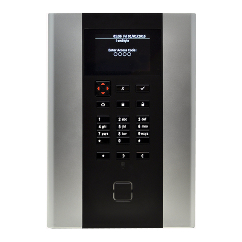
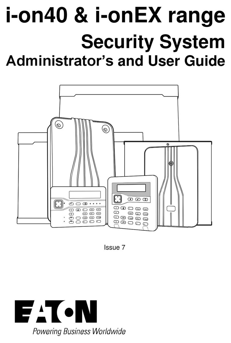
Eaton i-on30R+ User manual

Scantronic
i-on Security System User Guide
For i-on30R+, i-on40H+, i-onG2SM, i-onG3MM and i-onG3LM
(a separate user guide is available for i-on Compact)
About this guide
Thank you for choosing an i-on
alarm system – one of the most
advanced and trusted products
available today to protect people
and property.
This guide provides an
introduction to i-on alarm systems
for users. It describes the main
components, the key features and
how to carry out typical day-to-
day tasks.
If you need additional
information, including details of
the options in the User menu,
please refer to the
Administration
and User Manual
. This and other
publications referred to in this
guide are available from the
Scantronic web site.
Note: Some features described in
this guide may not be available,
depending on configuration.
Please ask your installer if you
would like them to be available.
About i-on alarm
systems
The i-on range of alarm systems
are suitable for domestic and
commercial properties and can
use wired and/or wireless (radio)
detectors, depending on the panel
and peripherals selected.
Support is provided for a wide
range of communication options,
configuration settings and
peripheral devices, which gives
the flexibility needed to customise
the system to match the needs of
the most demanding applications.
Contents
About this guide ............. 1
About i-on alarm systems ..... 1
System components .......... 2
Control unit.......................... 2
Keypads............................. 2
Detectors............................ 2
Scantronic SecureConnect™............ 3
Proximity tags........................ 3
Internal radio sounders ................ 3
External sirens ....................... 3
Network cameras ..................... 3
Remote controls ...................... 3
Hold-up alarm transmitters ............. 3
Output devices ....................... 3
Operational features .......... 4
Comprehensive set/unset flexibility ...... 4
Alarm communication ................. 4
User options ......................... 4
Users and user types .................. 4
HUA/panic alarms .................... 4
Full logging.......................... 4
Test options ......................... 5
Installer remote access ................ 5
Jamming and tamper monitoring ....... 5
Using the system ............ 5
Keypad keys ......................... 5
About the standby screen .............. 6
Setting the system .................... 6
Unsetting the system.................. 6
Managing alarms ..................... 7
Managing alerts ...................... 7
Accessing the User menu .............. 8
Omitting zones ....................... 8

Page 2
Connecting to a network
Your system has a built-in Ethernet port
for optional connection to your home or
office network, and the internet. Optional
modules also allow connection to a Wi-Fi
network, or to access the internet over a
mobile (4G/3G/2G) network.
Connecting your system to a network
enables:
•You to (for example) set, unset and
monitor your system over the internet
from your phone or tablet.
•Your system to be updated
automatically with the latest software
and new features.
•An installer to configure, monitor and
administer your system remotely (if
permitted).
•You to access a virtual keypad through
a web browser.
•Your system to communicate alarms
to an Alarms Receiving Centre (ARC)
over the internet. (Communication via a
landline is also possible.)
System components
This section outlines typical components
that your alarm system may include. Your
installer may have added other items,
depending on your requirements.
If there are components described here
that you would like to add to your system,
please contact your installer.
Control unit
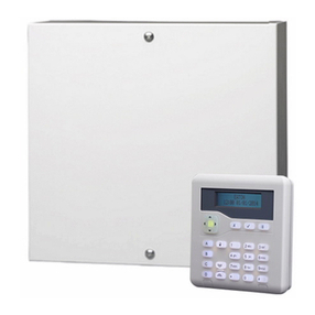
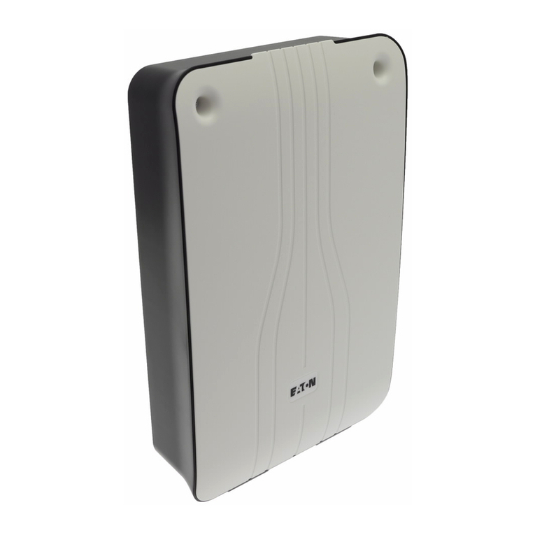
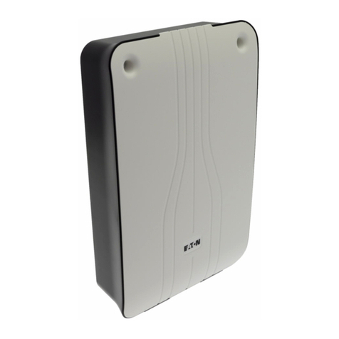
The control unit is the main processing
unit of the alarm system and is usually
located out of sight. Please ensure that it
is accessible for your installer to carry out
periodic maintenance tasks.
The control unit must be opened only
by an installer. If you attempt to do this
yourself, an alarm will be sounded, and
you may need your installer to reset the
system.
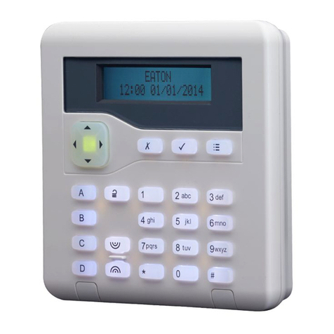
Keypads
Keypads provide the
main means of
operating the system,
such as to set or unset
the system, access
options and
acknowledge alarms.
There are several different types and styles
of keypad, including radio keypads, which
communicate with the system wirelessly.
You can identify yourself to the system
by entering your unique access code at
the keypad. Alternatively, if the keypad
includes a proximity tag reader, you can
simply present your proximity tag.
The LCD display shows messages, prompts
and options that guide you through the
user interface.
Detectors
Detectors are devices that detect alarm
conditions. Some models connect
wirelessly to the system (via radio), others
use physical wire.The following shows
some popular examples.
Passive Infra-Red (PIR)
movement detector.
Pet-tolerant versions are
available.
Dual-technology (PIR and
microwave) movement
detector. These are suitable
for more demanding
environments such as
garages and conservatories
(please ask your installer
for advice).
Smoke detector.
Slimline door contact and/
or shock sensor – to detect
when doors are opened, or
when a door or window is
forced.

Page 3
Perimeter PIR detector – to
monitor external areas such
as gardens. Dual-sensor
technology and pet-tolerant
mode ensure reliable
outside operation.
Note: Other detectors are available –
please contact your installer for details.
Note: Since there is normally only one
detector per zone, the terms “zone” and
“detector” are often used interchangeably.
Scantronic SecureConnect™
The SecureConnect app allows
you to monitor and control
your alarm system over the
internet from your phone or
tablet.
Medical/social care transmitters
These pendants
and wrist-worn
transmitters
allow the wearer
to signal that
medical or social-
care assistance is
needed.
Proximity tags
Each user can have a unique
proximity tag. When presented to a
keypad, the tag performs the same
action as entering an access code.
Proximity tags make it easier for you to set
or unset the system, and there is no need
to remember an access code.
Remote controls
Each user can have a
portable remote control to
set or unset the system or
operate output devices from
a distance.
Internal radio sounders
These are intended for use
in areas that are out of
audio range of a keypad
but where you need to
hear alarms, entry tones,
exit tones and other
sounds.
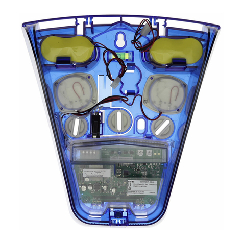
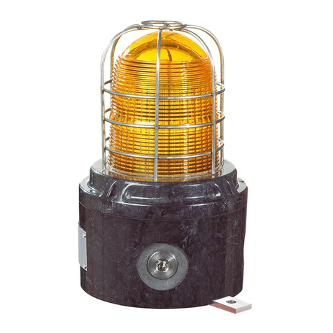
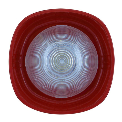
External sirens
These are mounted
externally, high up in
a visible location for
deterrence. They include
a powerful sounder and
strobes. Wired and radio
sirens are available.
Several radio sirens can
be used for strategic
placement around your
property.
Network cameras
Internal and external network cameras are
available. These allow the control unit to
record images when an alarm occurs.
You can view the images through
the system log, including via the
SecureConnect app. SecureConnect can
also send images automatically to an email
address when an alarm occurs.
Hold-up alarm transmitters
Small portable
Hold-Up Alarm (HUA)
transmitters, also
known as Panic Alarms
(PAs), allow you to start
a hold-up alarm from
anywhere in range of
your control unit.
Output devices
Your installer can set up your alarm system
to switch external devices, such as lights or
heating systems, on or off.
Devices can switch on or off automatically,
such as when the system is set or when
an alarm occurs. Alternatively, you can

Page 4
switch them on or off manually from a
keypad, using a remote control or from the
SecureConnect app.
Operational features
This section provides an overview of other
operational features of i-on alarm systems
from a user’s perspective.
Comprehensive set/unset flexibility
There are many options available to
the installer to configure the setting/
unsetting process to match your specific
requirements.
If at any time, your requirements change,
please contact your installer, who may
be able to adjust the set/unset procedure
without making any physical changes.
Your system is configured either as a part-
setting system or as a partitioned system:
Part-setting system
In a part-setting system, the system can set
in one of four ways: either full set or one
of three part sets (part set B, C or D). When
the system is full set, all zones are set.
When the system is part set, only the zones
that belong to the part set are set.
A part set may, for example, set the
downstairs areas, leaving the upstairs
unset (e.g. for use during the night).
Partitioned system
A partitioned system is designed for larger
installations, such as office blocks occupied
by several companies.
A partitioned system consists of several
partitions (perhaps one per company) that
can be individually set or unset without
affecting the others.
In addition, each partition can be set or
part set (part set B, C or D) in exactly the
same way as for a part-setting system.
Alarm communication
When the system detects an alarm, it starts
the external sounder/strobe units and
operates internal sounders, including the
sounder in keypads.
If you wish, your installer can also
configure the system to communicate
alarms externally to:
•An Alarm Receiving Centre (ARC), via
the internet or a fixed-line or mobile
telephone network.
•An email address (via SecureConnect).
•A phone using a text or speech
message.
Note: Communications via the internet
is provided as standard. Connecting the
control unit to a mobile (4G/3G/2G) or
fixed-line (PSTN) phone network requires
the installer to fit a plug-on module.
User options
Authorised users can access a User
menu from a keypad. The menu contains
options to add users, omit zones, view log
information, test the system, configure the
system and switch devices (outputs) on or
off.
You can find full details of the user options
in the
Administration and User Manual
.
Users and user types
i-on gives you the ability to define many
different users, each of which can have a
unique access code, proximity tag, remote
control, medical/social care pendant and
HUA transmitter.
Each user has a user type, such as Normal
User, Admin User or Master User. The user
type determines the privileges that the
user has to the system.
HUA/panic alarms
You can generate Hold-Up Alarm
(HUA), otherwise known as a panic
alarm, from a keypad, a remote
control, hand-held HUA transmitter
or using a separate panic button.
Page 5
Full logging
The control unit logs all actions, alarms
and alerts.You can review the logged
events through the User menu.
Test options
The User menu contains a comprehensive
set of options that you can use to test the
system or to determine the owner of a
device such as a proximity tag or remote
control.
Installer remote access
The installer has a separate Installer menu,
which contains the options needed to
configure your system. The menu can be
accessed through a keypad.
An alternative is to allow the installer
to access your system remotely over
the internet, which may provide service
benefits.
You have the ability to enable or disable
remote access as required through the
User menu.
Jamming and tamper monitoring
i-on alarm systems use advanced
techniques to monitor your system
continuously for possible jamming or
tamper attacks.
Using the system
This section describes typical tasks that
you may need to carry out from time to
time once the system is set up.
Note: For further information about
these and other tasks, please refer to the
Administration and User Manual
.
Keypad keys
Figure 1 shows the layout of keys on a
typical keypad.
The purpose of each key (other than the
numerical keys) is described next.
Figure 1. Typical keypad keys
Navigation key:
Scrolls up, or moves the
cursor left.
Scrolls down, or moves the
cursor right.
Changes the value, displays
further information, or inserts
a space.
Changes the value, or
deletes the character to the
left.
The key glows red or green to
indicate system status (green
= normal; red = alarm/fault).
This key exits an option or
cancels a change.
Confirms an action, such
as selection of an option or
acknowledgement of an alarm.
Pressing this key gives you
access to the user menu
when the standby screen is
displayed (see page 7).
For a part-setting system, this
fully sets of the system*. For a
partitioned system, it fully sets
partition 1*.

Page 6
For a part-setting system,
these set part set B, C or D*.
For a partitioned system, they
fully set partition 2, 3 and 4
respectively*.
Unsets the system.
A Hold Up Alarm (HUA) is
started when both of these
keys are pressed (if enabled
by the installer).
*This is the default action; the installer can
configure these keys perform a different
setting action, or to operate an output.
About the standby screen
When the system is idle (either while set
or unset), the display shows the “standby
screen”. For example:
i-on40H+
10:43 03/12/2021
Setting the system
Readying the system to start an alarm if
someone moves into a protected area is
called “setting” the system.
You can set your system using a variety of
different methods, depending on system
configuration. The following explains a
typical method using a keypad.
Note: Please refer to the
Administration
and User Manual
for full details.
1. Enter your access code or present your
proximity tag at the keypad. If you
enter your access code, the display
shows a * for each completed digit:
Enter Access Code:
(* )
2. If setting options are displayed, you
can press or followed by to
choose the option you require:
Setting Options
Full Set All
•
Full Set/Fulll Set All
: To set the whole
system. Alternatively, press the A
key*.
•
Part Set B\C\D
: To set part set B, C or
D only. Alternatively, press the B, C
or D key*.
•
Partitions
: To set or part set a
partition. Alternatively, press the B, C
or D key to full set a partition*.
*Your installer may have configured
the system to allow you to quick set
using A, B, C or D without entering an
access code or presenting a proximity
tag first.
3. You will hear a continuous exit tone
(unless the system is configured for
silent or instant setting).
The system sets when one of the
following occurs, depending on how
the system is configured:
•Immediately.
•After a period of time.
•When you exit the premises.
The A, B, C or D key illuminates to
indicate the set status (unless disabled
by the installer). For example, in a part-
setting system, the A key is illuminated
if the system is fully set.
Unsetting the system
Disarming the system so that people can
move freely is called “unsetting”.
To unset the system from a keypad:
1. Enter through the designated entry
route. Do not stray from this route –
you may cause an alarm.
2. If you hear a tone, go directly to the
keypad, since you will have limited
time to unset the system before it
generates an alarm.
3. Enter your access code or present your
proximity tag.

Page 7
Managing alarms
If there is an alarm, you will need to
silence the sirens and sounders (if they are
still running), acknowledge the cause of the
alarm and reset the system.
Note: Please refer to the
Administration
and User Manual
for full details.
To silence, acknowledge and reset an
alarm:
1. Make sure that it is safe to enter the
premises.
2. Enter your access code or present your
proximity tag in the normal way.This
silences the alarm (if the sirens and
sounders are still operating).
3. The navigation key glows red and the
display shows, for example:
Press tick to reset
Zone 000
The display alternates between
showing the zone number (e.g. “Zone
000”) and alarm type.
4. If you see “reset” in the message (see
above):
•Press − this acknowledges the
alarm and resets the system. The
system returns to standby and is
ready to set again.The navigation
key returns to its normal (green)
state.
If you see “Call Installer” or “Call ARC”
at the top of the screen:
•Press − this acknowledges the
alarm, but you will need to call the
installer or ARC to reset the system.
Although the system is not reset, you
will still be able to set and unset the
system normally. The navigation key
and applicable set/unset icons stay
red until the alarm is reset.
Managing alerts
An alert is an event that is not directly
related to an intrusion event, such as a low
battery or a communications fault.
An alert does not cause an alarm sound.
Instead, the navigation key on keypads
glows red when the system is unset, and
keypads give a short “beep” approximately
every second if the alert has not been
acknowledged.
To view the cause of the alert:
1. Make sure the system is unset and that
the keypad shows the standby screen.
2. Before entering your access code,
press .
3. Enter your access code or present
your proximity tag to the keypad. The
bottom line displays the most recent
alert. For example:
Tick to continue
Bat Low/Missing
4. Press to acknowledge that you have
read the alert. Repeat this step for any
other alerts that may be active.
5. If you see a message similar to the
following:
RESET FAULTS
Z041 FREEZER
This indicates that the alert has been
caused by a “technical” zone (which
typically is used to monitor equipment
such as a freezer), and the detector
is still active. If you can, rectify the
problem and repeat the procedure.
If you cannot clear the fault, please
contact your installer.
6. The standby screen is displayed and
the beeping stops. The navigation key
continues to glow red until the faults
are rectified.

Page 8
Accessing the User menu
The User menu gives access to user
options such as to omit zones, view log
information and add new users. The range
of options available to you depends on
your user type (privileges).
To access the User menu:
1. Make sure the display shows the
standby screen.
2. Press .
3. Enter your user code:
Enter Access Code:
(* )
The first option is displayed:
MENU
Omit Zones >
Press or to scroll through the
options, followed by to select the
option you require. The options are
fully documented in the
Administration
and User Manual
.
4. To leave the menu and return to the
standby screen, press (if necessary,
several times).
Omitting zones
You can omit a zone before setting the
system. Omitting a zone prevents it from
generating an alarm if the zone is triggered
while the system is set. You may, for
example, want to omit a zone that protects
a garage to enable access without causing
an alarm while the system is set.
Note: The zone returns to normal operation
when the system is unset.
Note: You can omit only those zones that
the installer has specified can be omitted.
To omit zones:
1. Access the User menu, as described in
the previous section.
2. Select the
Omit Zones
option. The first
zone you can omit is displayed. For
example:
OMIT ZONES
Zone 000 I
An “O” is displayed at the end of the
line if the zone is Omitted. An “I” is
displayed if the zone is Included.
3. Press or to display the zone you
wish to omit, then to mark it for
omission. Press again if you made
a mistake and want the zone to be
included.
Repeat this step for any other zones
you wish to omit (or change to be
included).
4. Press to store changes.
This product must be installed and
maintained only by qualified service
personnel.
The information, recommendations, descriptions and safety
notations in this document are based on Eaton Corporation’s
(“Eaton”) experience and judgment and may not cover all
contingencies. If further information is required, an Eaton sales office
should be consulted. Sale of the product shown in this literature is
subject to the terms and conditions outlined in appropriate Eaton
selling policies or other contractual agreement between Eaton and
the purchaser.
THERE ARE NO UNDERSTANDINGS, AGREEMENTS, WARRANTIES,
EXPRESSED OR IMPLIED, INCLUDING WARRANTIES OF FITNESS
FOR A PARTICULAR PURPOSE OR MERCHANTABILITY, OTHER
THAN THOSE SPECIFICALLY SET OUT IN ANY EXISTING CONTRACT
BETWEEN THE PARTIES. ANY SUCH CONTRACT STATESTHE ENTIRE
OBLIGATION OF EATON. THE CONTENTS OFTHIS DOCUMENT
SHALL NOT BECOME PART OF OR MODIFY ANY CONTRACT
BETWEEN THE PARTIES.
In no event will Eaton be responsible to the purchaser or user in
contract, in tort (including negligence), strict liability or other-wise
for any special, indirect, incidental or consequential damage or loss
whatsoever, including but not limited to damage or loss of use of
equipment, plant or power system, cost of capital, loss of power,
additional expenses in the use of existing power facilities, or claims
against the purchaser or user by its customers resulting from the use
of the information, recommendations and descriptions contained
herein. The information contained in this manual is subject to change
without notice.
© 2022 Eaton.
Eaton, Security House, Vantage Point Business Village,
Mitcheldean, GL17 0SZ. www.myscantronic.com
SecureConnect is a trademark of Eaton.
Part number 14199583
Issue 3 24/01/2022
This manual suits for next models
5
Table of contents
Other Eaton Security System manuals

Eaton
Eaton BiWire Ultra User manual

Eaton
Eaton i-on Style User manual

Eaton
Eaton i-on Style User manual

Eaton
Eaton BG User manual

Eaton
Eaton Expertline User manual

Eaton
Eaton i-on16 User manual

Eaton
Eaton PH1 User manual

Eaton
Eaton 401-TF Manual

Eaton
Eaton BiWire Ultra EF009SB User manual

Eaton
Eaton XB12 User manual
Popular Security System manuals by other brands

Voyager
Voyager WVHS43 manual

FingerTec
FingerTec TA100 DIY SERIES user guide

patura
patura 15631 Mounting instructions

Marmitek
Marmitek PROGUARD800 Series user manual

Federal Signal Corporation
Federal Signal Corporation 400HMK-AC instruction sheet

Zerio-Plus
Zerio-Plus EDA-Z5008 Installation & operation manual