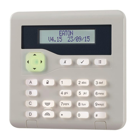
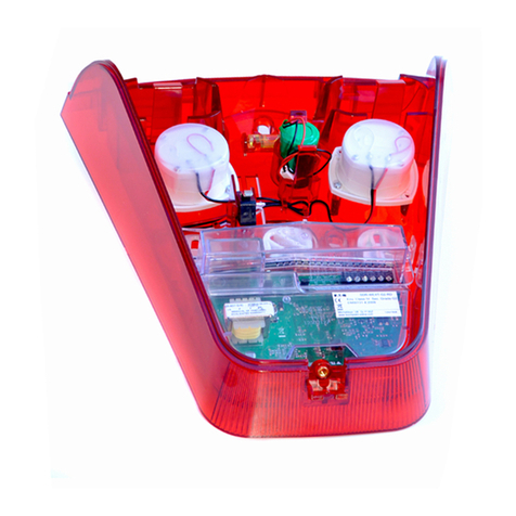
Eaton Scantronic i-on10 User manual

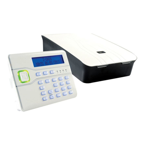
Scantronic
i-on10
Security System
Configuration Guide
Issue 2
Control unit software version 7.01.xx

Page ii
© Eaton 2022
The information, recommendations, descriptions and safety notations in this document are based on Eaton Corporation’s (“Eaton”)
experience and judgment and may not cover all contingencies. If further information is required, an Eaton sales office should be
consulted. Sale of the product shown in this literature is subject to the terms and conditions outlined in appropriate Eaton selling policies
or other contractual agreement between Eaton and the purchaser.
THERE ARE NO UNDERSTANDINGS, AGREEMENTS, WARRANTIES, EXPRESSED OR IMPLIED, INCLUDING WARRANTIES OF
FITNESS FOR A PARTICULAR PURPOSE OR MERCHANTABILITY, OTHER THAN THOSE SPECIFICALLY SET OUT IN ANY
EXISTING CONTRACT BETWEEN THE PARTIES. ANY SUCH CONTRACT STATES THE ENTIRE OBLIGATION OF EATON. THE
CONTENTS OF THIS DOCUMENT SHALL NOT BECOME PART OF OR MODIFY ANY CONTRACT BETWEEN THE PARTIES.
In no event will Eaton be responsible to the purchaser or user in contract, in tort (including negligence), strict liability or other-wise for
any special, indirect, incidental or consequential damage or loss whatsoever, including but not limited to damage or loss of use of
equipment, plant or power system, cost of capital, loss of power, additional expenses in the use of existing power facilities, or claims
against the purchaser or user by its customers resulting from the use of the information, recommendations and descriptions contained
herein. The information contained in this manual is subject to change without notice.
The i-on application includes the mbed TLS library, developed by a third party and licensed under the Apache 2.0 license. The Apache
2.0 license can be found at: http://www.apache.org/licenses/LICENSE-2.0
Guardall is a registered trademark of Guardall Limited.
About this Guide
This guide is for people who need to install and configure an i-on10 intrusion system. The
guide gives an introduction to i-on10, provides pre-installation information, and explains
how to configure the unit using the options in the Installer menu of the user interface.
Detailed installation information is given in the separate i-on10 Installation Instructions.
Other Publications
The following additional publications are available:
i-on10 User Guide –This provides an overview of the i-on10 intrusion system,
including system components, key features and typical day-to-day tasks for end
users.
i-on Series Administration and User Manual –This provides detailed information
about how to set and unset the system, manage alarms and use the User menu
options.
Installation Instructions –Included in the packaging of each hardware device
(such as a control unit or detector) are concise installation instructions that explain
how to install that device.

Page iii
Contents
About this Guide...............................................................................................................ii
Other Publications............................................................................................................ ii
Chapter 1: Introduction to i-on10 ..................................................................6
Summary of features........................................................................................................6
System bus ......................................................................................................................8
Part-setting.......................................................................................................................8
Grade 2 compliance.........................................................................................................8
Peripheral devices............................................................................................................8
Keypads........................................................................................................................8
KEY-EP external proximity tag reader..........................................................................9
Detectors (zones) .......................................................................................................10
Plug-by (digital communicator) ...................................................................................10
Output device..............................................................................................................10
Sounders....................................................................................................................10
Chapter 2: Installing and Maintaining i-on10 ............................................12
Planning the installation .................................................................................................12
Choosing the installation locations..............................................................................12
Checking power availability ........................................................................................12
Detector (zone) wiring types.......................................................................................14
Checking cable requirements .....................................................................................15
Installing the hardware...................................................................................................16
Maintaining the system...................................................................................................17
Chapter 3: Configuring the System − Getting Started ..............................18
Initial Power-up Procedure.............................................................................................18
Entering the Installer menu ............................................................................................20
Saving Changes .........................................................................................................21
Code Lockouts............................................................................................................21
Transferring to another keypad...................................................................................21
Understanding the User Interface...................................................................................21
Selecting Options........................................................................................................21
Changing a Setting.....................................................................................................22
Entering Text ..............................................................................................................22
Exiting the Installer Menu...............................................................................................22
Exiting with Faults.......................................................................................................22
Resetting (Defaulting) the System..................................................................................23
Restoring Control Unit Factory Defaults .....................................................................23
Resetting a keypad's address.....................................................................................23
Resetting Access Codes.............................................................................................23
Chapter 4: Detectors/Devices Menu............................................................25
Detectors........................................................................................................................25
Program Zones...........................................................................................................25
Address Bus Device.......................................................................................................31
Adding a keypad.........................................................................................................32
Re-scanning the bus...................................................................................................32
Wired Keypads...............................................................................................................33
Address Bus Device ...................................................................................................33

Page iv
Edit Keypad................................................................................................................33
Delete Keypad............................................................................................................35
Enable Keypad ...........................................................................................................35
Replace Keypad .........................................................................................................35
Radio Keypads...............................................................................................................36
KEY-RKPZ..................................................................................................................36
Chapter 5: Outputs Menu .............................................................................38
Wired Outputs................................................................................................................38
Plug-By Outputs.............................................................................................................43
Chapter 6: Setting Options Menu................................................................44
Full Set and Part Set options..........................................................................................44
Name..........................................................................................................................44
Exit Mode....................................................................................................................44
Settle Time .................................................................................................................45
Confirm Set.................................................................................................................45
Exit Time.....................................................................................................................46
Entry Time ..................................................................................................................46
Extended Entry Time ..................................................................................................46
Alarm Response.........................................................................................................46
Siren Delay.................................................................................................................46
Siren Time ..................................................................................................................46
Pt.set Final Exit...........................................................................................................46
Pt.set Entry Route.......................................................................................................47
Strobe on Set..............................................................................................................47
Strobe on Unset..........................................................................................................47
Chapter 7: System Options Menu ...............................................................48
User Options..................................................................................................................48
User Access ...............................................................................................................48
User Reset..................................................................................................................49
Keypad Text ...............................................................................................................50
Restore Defaults.............................................................................................................50
Staged Defaults..........................................................................................................50
Factory Defaults..........................................................................................................51
Installer Options.............................................................................................................51
Installer Name.............................................................................................................51
Installer Code..............................................................................................................51
Installer Timeout.........................................................................................................52
Service Date...............................................................................................................52
Service Banner...........................................................................................................52
Confirmation...................................................................................................................52
Confirmation Mode .....................................................................................................52
Confirmation Time ......................................................................................................53
Entry Alarm Delay.......................................................................................................53
After Entry...................................................................................................................53
Entry Keypad Lock......................................................................................................54
Sounder On................................................................................................................54
Siren On .....................................................................................................................55
Unconfirmed Reset.....................................................................................................55
Confirmed Reset.........................................................................................................55
HUA Response...........................................................................................................56

Page v
HUA Confirm Time......................................................................................................56
Tamper as Tamper Only.............................................................................................56
Abort Time..................................................................................................................57
Auto Rearm ................................................................................................................57
Hardware........................................................................................................................57
Panel Name................................................................................................................57
Wired Zone Type........................................................................................................57
Panel Loudspeaker.....................................................................................................57
Mains Fail Delay.........................................................................................................58
Linked Zone Time.......................................................................................................58
Panel Tamper Return .................................................................................................58
Reset Codes Pins.......................................................................................................59
Date and Time................................................................................................................59
Set Time & Date .........................................................................................................59
Updates..........................................................................................................................59
Language....................................................................................................................59
Chapter 8: Communications Menu..............................................................60
Line Fail Response.........................................................................................................60
Line Fail Delay ...............................................................................................................60
Chapter 9: Test Menu....................................................................................61
Sirens and Sounders......................................................................................................61
Wired Sirens...............................................................................................................61
Loudspeakers.............................................................................................................61
Wired Keypads ...........................................................................................................61
KEY-RKPZ..................................................................................................................61
Wired Keypad.................................................................................................................61
Radio Keypads...............................................................................................................61
KEY-RKPZ..................................................................................................................61
Walk Test.......................................................................................................................61
Zone Resistances...........................................................................................................62
Zone Status....................................................................................................................62
Wired Zones...............................................................................................................62
Signal Strengths.............................................................................................................63
Radio Keypads ...........................................................................................................63
Outputs...........................................................................................................................63
Prox Tags.......................................................................................................................63
Locate Bus Device .........................................................................................................63
Chapter 10: View Log Menu .........................................................................64
Log Events.....................................................................................................................64
Chapter 11: About Menu...............................................................................65
Panel..............................................................................................................................65
Bus.................................................................................................................................65
Keypads.........................................................................................................................65
Appendix A: Log Messages .........................................................................66
Introduction ....................................................................................................................66
Log messages................................................................................................................66
Appendix B: Installer Menu Map .................................................................69

Page 6
Chapter 1: Introduction to i-on10
The i-on10 control unit is a grade 2, 10-zone control unit for wired detectors and up to four
keypads. The control unit has been designed to satisfy the most demanding requirements
of alarm-systems professionals for domestic and small commercial applications, and is
both easy to install and robust.
Summary of features
The i-on10 features:
Grade 2 compliance.
On-board connections for up to 10 wired zones, a wired siren/strobe unit, external
loudspeaker, and one open-collector output.
An RS485 bus for connecting up to four keypads.
One 8-output plug-by do port.
Support for one full-set level and up to three part-set levels.
Metal case, fitted with a 1A power supply and space for a 12Vdc 7Ah backup battery.
Back and lid tamper switches.
Support for up to 10 users.
Note: The maximum number of on-board zones is for Fully-Supervised Loop (FSL) or
2-wire Closed Circuit (CC) wiring. If 4-wire CC wiring is used, the maximum number of
on-board zones is halved, unless an optional ADP-10CC board is fitted.
The i-on10 is a member of the i-on range of control units. Table 1 specifies the features
and system limits for each control unit in the i-on range.

Introduction to i-on10
Page 7
Table 1: i-on range feature comparison
Feature
i-on Compact
i-on10
i-on30R+
i-on40H+
i-onG2SM
i-onG3MM
EN 50131 security grade
2
2
2
2
2
3
Zones
Max on-board radio zones
20
0
30
30
0
0
Max on-board wired zones (See note)
0
10
0
10
10
10
Max zones on expanders, keypads, etc.
0
0
30
40
40
190
Max wired and radio zones (system wide)
20
10
60
80
50
200
Bus
RS485 Buses
0
1
1
1
1
2
Max bus devices
0
4
20
20
20
50
Outputs
Max on-board radio outputs
20
0
10
10
0
0
On-board transistor outputs
0
1
2
2
1
2
On-board relay outputs
0
0
0
2
0
2
Max outputs on expanders, keypads, etc.
0
0
30
40
50
200
On-board plug-by outputs
0
12
0
12
12
16
On-board siren\strobe connections
No
Yes
Yes
Yes
Yes
Yes
Max custom outputs
0
0
4
4
5
20
Max outputs (system wide)
20
1
30
40
50
200
Ports
Ethernet port
Yes
No
Yes
Yes
Yes
Yes
Plug-on module port
Yes
No
Yes
Yes
Yes
Yes
USB port
Yes
No
No
No
No
No
On-board loudspeaker connections
0
1
1
1
1
1
Micro SD card slot
Yes
No
Yes
Yes
Yes
Yes
Devices
Max wired keypads (note 1)
0
4
20
20
20
50
Max i-rk01 and KEY-RAS radio keypads
2
0
4
4
5
20
Max external radio siren\strobe units
2
0
4
4
5
20
Max network cameras
2
0
4
4
5
20
Max internal radio sounders
2
0
4
4
5
20
Max Wireless Access Modules
2
0
4
4
5
20
Case
Control unit case
Plastic
Metal
Plastic
Plastic
Metal
Metal
Battery
1 (2.2Ah)
1 (7Ah)
1 (7Ah)
1 (7Ah)
1 (7Ah)
1 (17Ah)
Power Supply Unit (PSU)
0.5A
1.0A
1.0A
1.0A
1.0A
2.0A
PSU current reserved for battery charging
100mA
180mA
180mA
180mA
180mA
750mA
Back and lid tamper
Yes
Yes
Yes
Yes
Yes
Yes
Software
Users
20
10
30
50
50
200
Part sets (including per partition in partitioned mode)
3
3
3
3
3
3
Max partitions
0
0
4
4
5
20
Mandatory log events
250
250
750
750
750
1500
Non-mandatory log events
50
100
250
250
750
1500
Calendar set events
0
0
10
10
10
50
Calendar set exceptions
0
0
30
30
30
30
Max shunt groups
0
0
4
4
5
20
Max simultaneous keypad sessions
1
1
4
4
5
10
Web interface
Yes
No
Yes
Yes
Yes
Yes
SecureConnect and web browser interface
Yes
No
Yes
Yes
Yes
Yes
Firmware update via web interface, cloud auto update,
or SD card
Yes
No
Yes
Yes
Yes
Yes
Firmware update via USB port
Yes
No
No
No
No
No
Multilanguage support (-EU variant)
Yes
No
Yes
Yes
Yes
Yes

Introduction to i-on10
Page 8
Note 1: The maximum number of wired keypads for i-on10 includes KEY-RKPZ keypads.
A KEY-RKPZ is a radio keypad that uses a KEY-RKBS base station wired to the bus. Up
to two KEY-RKPZ keypads can connect to the same base station, but this feature cannot
be used to increase the total number of keypads beyond the limit shown in Table 1.
System bus
i-on10 has a system bus, which is used to connect wired keypads or KEY-RKBS base
stations to the control unit. The devices can connect to the bus using a "daisy chain" or
star layout, as shown in Figure 1.
Figure
1.
Daisy chain and star connections
Each keypad has a unique bus address, which it obtains from the control unit either during
the commissioning stage of a new installation, or when the installer adds the keypad from
the Installer menu. Each keypad stores its address in non-volatile memory.
Part-setting
The i-on10 can set in one of four ways: either full set or one of three part sets (part set B,
C or D). Each zone can belong to one or more part sets (using the Part Set attribute).
When the system is full set, the control unit sets all zones, irrespective of the part set they
belong to. When part set, the control unit sets only those zones that belong to the part set.
Grade 2 compliance
The i-on10 is suitable for use in systems that need to conform to security grade 2
requirements. For grade 2, you must fit an appropriate plug-by communicator.
Default configuration settings are applicable to grade 2. Note that if you certain settings,
the system may no longer comply with grade 2.
Peripheral devices
This section gives an overview of each type of additional hardware device supported.
Keypads
Keypads are used by installers to configure the system, and by users to set or unset the
system. Up to four keypads can be used.
i-on10
i-on10

Introduction to i-on10
Page 9
The keypads supported by i-on10 are listed in Table 2. Many of these include a built-in
proximity reader, which allows users to set or unset the system using a proximity tag.
Note: i-on10 does not support zones and outputs connected to a keypad.
Note: Do not install a proximity reader closer than one meter to any other type of proximity
reader, otherwise the devices may not work correctly.
Table 2: Keypad features
Feature
KEY-K01
i-kp01
KEY-KP01
KEY-KPZ01
KEY-FKPZ
KEY-RKPZ*
Wired keypad
Yes
Yes
Yes
Yes
Yes
No
Radio keypad
No
No
No
No
No
Yes
Built-in proximity reader
No
Yes
Yes
Yes
Yes
Yes
KEY-EP external proximity reader terminals
No
No
Yes
Yes
Yes
No
Zones (not supported with i-on10)
0
0
0
2
2
2
Outputs (not supported with i-on10)
0
0
0
1
1
0
Loudspeaker terminals
0
0
0
0
1
0
Two-line by 20-character backlit LCD
display
Yes
Yes
Yes
Yes
Yes
Yes
Illuminated four-way switch (the “navigation
key”), which is used to navigate through
menus
Yes
Yes
Yes
Yes
Yes
Yes
LEDs behind the navigation key to show the
fault status of the system
Yes
Yes
Yes
Yes
Yes
Yes
Numeric keypad for entering access codes
and keying in text
Yes
Yes
Yes
Yes
Yes
Yes
Dedicated A, B, C and D keys, which can be
programmed to set individual part sets, or
allocated to control an output.
Yes
Yes
Yes
Yes
Yes
Yes
Keys for “yes”, “no” functions
Yes
Yes
Yes
Yes
Yes
Yes
Unset key
Yes
Yes
Yes
Yes
Yes
Yes
Hold-Up Alarm (HUA) keys
Yes
Yes
Yes
Yes
Yes
Yes
User menu key and an automatic timeout
from the user menu
Yes
Yes
Yes
Yes
Yes
Yes
Internal sounder to give setting tones, alarm
sounds, etc
Yes
Yes
Yes
Yes
Yes
Yes
Backlit keys
Yes
Yes
Yes
Yes
Yes
Yes
*The KEY-RKPZ is a two-way battery-powered radio keypad. This keypad communicates
over a radio link to a base station connected to the bus, which acts as a communications
bridge between the keypad and the control unit. You can use a KEY-RKPZ in the same
way as a wired keypad to configure the system, set or unset the system, etc.
KEY-EP external proximity tag reader
A KEY-EP external proximity tag reader can connect to a KEY-KP01, KEY-KPZ01 or
KEY-FKPZ keypad to enable the system to be to set or unset externally.

Introduction to i-on10
Page 10
Detectors (zones)
Detectors are the physical devices that detect alarm conditions. A zone is the lowest-level
item within the intrusion system that can be set or unset.
Detectors supported by i-on10 include:
XCELW
XCELWPT
DETWDT-G2
DET-WDTPT-G2
DET-RSDC
M12
Note: Although it is possible to connect detectors in series and therefore to have more
than one detector in the same zone, it is not normal practice. Instead, there is normally
only one detector per zone and for this reason, detectors are often referred to as "zones"
within the intrusion system.
Wired detectors connect using standard alarm cable to the i-on10. Please refer to page 14
for details of the different wiring methods you can use.
Note: If 4-wire CC wiring is used, this may reduces the available number of zones to 5,
unless an ADP-10CC board is fitted.
All wired detectors with contacts that open and close are supported, as there is no protocol
involved.
Plug-by (digital communicator)
The i-on10 includes an 8-output plug-by communicator port, which allows the system to
communicate externally to an alarms-receiving site using a separate digital communicator
(purchased separately).
By default, the outputs are switched negative (from 12Vdc to 0V) when active. You can
program these outputs to be switched positive (from 0V to 12Vdc) when active.
Output device
A device such as an indicator, lighting system or third-party item of equipment can be
switched on or off using the transistor (open-collector) output available on the i-on10 PCB.
You can configure the output in the Installer menu to control the external device when, for
example there is an alarm in a specified zone.
By default, the output is switched negative (from 12Vdc to 0V) when active; you can
program it to be switched positive (from 0V to 12Vdc).
Sounders
Sounders indicate alarms, entry tones, exit tones and other conditions. There are various
types of sounder:
Keypad sounders −A sounder is built into each keypad.
External wired siren/strobe unit −The i-on10 provides connections to drive a
standard wired siren/strobe unit in Self-Activating Bell (SAB) or Self-Contained Bell
(SCB) mode. The Scantronic SDR-WEXT-G2 siren/strobe unit is supported, as are
other third-party units that have compatible connections.

Introduction to i-on10
Page 11
Loudspeakers −The i-on10 and KEY-FKPZ keypad have connections for a
loudspeaker, which you may want to use to increase the volume or location of
setting and unsetting tones. The loudspeaker must have an impedance of 16 Ohms.
You must not connect two loudspeakers in parallel to the same port.

Page 12
Chapter 2: Installing and Maintaining
i-on10
Planning the installation
Choosing the installation locations
When planning the installation, consider the following recommendations concerning the
locations of where to install the control unit and other devices.
Control unit
The control unit must be located:
Within the protected area (but not in an entry or exit zone).
Upright (battery at the bottom) on a wall or other flat surface to discourage tamper
attempts from the rear.
Out of sight of potential intruders.
Where maximum cable distances will not be exceeded (see page 16).
Keypads and proximity readers
Keypads and proximity readers should be located at a convenient height.
Keypads must be within the area protected by the intrusion system and ideally out of sight
of potential intruders.
Proximity readers or any keypad containing a proximity reader must not be located:
Within 1 metre of another proximity reader (including one located within another
keypad).
Behind a door, coat rack or other covering.
External siren
This must be located out of reach of intruders and vandals, but must be easily visible for
maximum deterrence.
Checking power availability
EN50131-1 or PD6662 Grade 2 requires the backup battery to be able to power the
system for at least 12 hours. The duration must include two 15-minute periods in alarm.
You must make sure that:
a) The control unit's 1.0A power supply has sufficient capacity to power all
connected devices. 180mA is reserved for battery charging.
b) The backup battery can provide sufficient power in the event of a mains failure.
If there is insufficient power available from the control unit or backup battery, consider the
use of additional power supplies.

Installing and Maintaining i-on10
Page 13
When considering the power drawn, include the control unit's PCB and all peripherals
powered by the control unit, including any plug-by communicator, keypads and wired
detectors.
Table 3 gives a summary of the current consumed by the i-on10 PCBs and popular
peripheral devices.
Table 3: Current Consumptions
Device
Current Consumption (In Alarm)
i-on10 PCB
Quiescent: 40mA
In alarm: 70mA
Wired PIR
15mA
KEY-FKPZ keypad
Quiescent: 25mA
In alarm: 65mA
i-kp01 keypad
Quiescent: 30/40/60mA (backlight off/on/bright respectively)
In alarm: 45/45/65mA (backlight off/on/bright respectively)
KEY-KPZ01,
KEY-KP01 or
KEY-K01 keypad
Quiescent: 35mA (backlight off, no external proximity reader)
In alarm: 65mA (backlight on, external proximity reader fitted)
SDR-WEXT
external siren/strobe
Quiescent: 35mA
In alarm: 225mA
Worked example
The following shows a simplified example of checking power availability.
Device (quiescent) Current
Control unit PCB 40mA
10 x PIRs at 15mA each 150mA
2 x KEY_FKPZ at 25mA each (backlights off) 50mA
Plug-by digital communicator 25mA
Siren 35mA
Total 300mA
During an alarm, the current consumptions are:
Device (in alarm) Current
Control unit PCB 70mA
10 x PIRs at 15mA each 150mA
2 x KEY_FKPZ at 65mA each 130mA
Plug-by digital communicator 150mA
Siren 225mA
Total 725mA
Since the control unit's power supply can provide 820mA (excluding battery charging), the
above shows that the power supply is able to power the system during an alarm (725mA).
The total amp-hours required for the battery for Grade 2 is:
(0.3A x 11.5h) + (0.725A x 0.5h) = 3.81Ah
A fully-charged, 7Ah battery can provide the charge required by the above example to
meet Grade 2 requirements.

Installing and Maintaining i-on10
Page 14
Detector (zone) wiring types
Before installation, you need to choose the wiring type (method) to use for any wired
detectors: Fully-Supervised Loop (FSL), 4-wire Closed Circuit (CC), or 2-wire CC, as
described below. You must use the same wiring type for all wired detectors.
You will need to ensure that all detectors are wired correctly and that you select the default
wiring type during the initial power-up procedure.
Fully Supervised Loop (FSL)
This uses a single pair of wires for each detector, with resistors at the end of the line and
across the alarm contact (Figure 2). The resistors allow the system to monitor for short-
circuit or open-circuit conditions to guard against cable tampering.
The End-of-Line (EOL) and alarm contact resistors can be any of the following values
(respectively): 2k2 and 4k7, 1k and 1k, 2k2 and 2k2, or 4k7 and 4k7. The resistance bands
for FSL are as shown in Table 4.
Figure
2.
FSL connections for 2k2/4k7, 1k/1k, 2k2/2k2 and 4k7/4k7
FSL with 8k2/8k2 resistors (for use with Guardall®resistors)
Figure 3 shows the wiring method when using 8k2 and 8k2 resistors.
Figure
3.
FSL connections for 8k2/8k2
Table 4: FSL Resistor Bands
Zone State
2k2/4k7 FSL
1k/1k FSL
2k2/2k2 FSL
4k7/4k7 FSL
8k2/8k2 FSL
Tamper
0k0 –1k759
0k0 - 0k799
0k0 –1k759
0k0 –3k759
0k0 –
Normal
1k76 –4k08
0k8 - 1k4
1k76 - 3k08
3k76 - 6k58
4k1 -
Alarm
4k081 –8k28
1k401 - 2k4
3k081 - 5k28
6k581 - 11k28
8k2 -
Tamper
> 8k28
>2k4
>5k28
>11k28
>9k8
Double Doors
If required, two door contacts can be connected to the same zone using the resistor
configuration shown in Figure 4. In this configuration, the zone must have the Double
EOL
Tamper
Alarm
Tamper
Alarm

Installing and Maintaining i-on10
Page 15
Doors attribute set (see page 31). The zone must use 4k7 shunt resistors and a 2k2 EOL
resistor.
Figure
4.
Two detectors per zone (Double Doors)
4-wire CC
This uses a separate pair of wires for the alarm and tamper contacts. No end-of-line
resistors are used. Selecting 4-wire CC normally halves the maximum number of wired
zones that can connect to the i-on10. However, an ADP-10CC board can be fitted to
convert the ten FSL zones to ten 4-wire CC zones. Without the board fitted, the control unit
supports five 4-wire CC zones. If you are using an ADP-10CC board, select 2-wire FSL
2k2/4k7 as the wiring type.
2-wire CC
This uses a single pair of wires for each detector. No end-of-line resistors are used.
Checking cable requirements
Standard cable type
Normally, the control unit requires standard 7/0.2 un-screened 4-core alarm cable for
wiring to keypads and wired siren/strobe units.
Screened cable
For maximum performance in environments where there is electromagnetic noise, use
twisted-pair screened cable with a characteristic impedance of 100-120 Ohms, such as
Belden 8132 or cable designed for RS485.
If screened cable is required:
1. Avoid earth loops by connecting the screen on the cable to mains earth at the
control unit but not at the keypad.
2. The continuity of the cable screen is most important and screens MUST be
continuous along the full length of the cable.
3. Where the cable enters any metal enclosure, ensure the screen is isolated from
the case.
Cable segregation
Segregate bus cabling to keypads from any other wiring, such as mains cables, telephone
cables, computer network cables and R.F. cables.
Keep cables to keypads clear of cables supplying extension loudspeakers or any high-
current devices.
Mains cable routing
Use separate cable-entry holes in the enclosure for mains and signal cables. Please refer
to the i-on10 Installation Instructions for details of the holes to use for each type of cable.
EOL
Tamper
Tamper
Alarm
Alarm

Installing and Maintaining i-on10
Page 16
Cable length and configuration (star or daisy chain)
You can connect devices either in daisy chain (serially), or in star (parallel) configuration at
the control unit connector (Figure 5). For star configurations, the cable length from control
unit to the most distant keypad should be kept short, and should not exceed 100m.
For a daisy-chain configuration, the total cable length should not exceed 1,000m.
Note that if there are only two arms in a star configuration, this is equivalent to a daisy-
chain configuration.
Bus termination
In some cases, the ends of the bus may need to be terminated to improve performance in
electrically noisy environments or where there are long cable runs. The control unit and
keypads have a termination link on their PCB. Fitting a jumper to the link adds a
termination to the cable.
In a daisy-chain configuration, fit the termination jumpers in the devices at each end of the
chain. In a star configuration, terminate at the two devices on the ends of the longest
cables (Figure 5).
Figure
5.
Bus termination
Installing the hardware
Details of how to install an i-on10 control unit are given in the separate i-on10 Installation
Instructions. Instructions are also provided in the packaging of each peripheral device
purchased.
After installing the hardware, you need to configure the system as described in the
remaining chapters of this guide.
i-on10
i-on10
i-on10

Installing and Maintaining i-on10
Page 17
Maintaining the system
After installation, the system should be inspected once or twice per year as follows:
Check the control unit for obvious signs of damage to the case or its lid.
Check the action of the tamper switch.
Check, and if necessary, replace the standby battery.
Check keypads and other devices for obvious signs of damage.
Test the action of all buttons on all keypads.
Clean the surface and display of each keypad using a clean, soft, dry cloth. Do not
use water, solvents or any proprietary cleaning materials.
Where applicable, check cabling for signs of damage or wear.
Gently clean the lenses of any PIRs with a clean, soft dry cloth. Do not use water,
solvents or any proprietary cleaning materials.
Walk test all detectors.
Test any external sounders and strobes.

Page 18
Chapter 3: Configuring the System −
Getting Started
This chapter explains how to:
Use the initial power-up procedure to configure the basic settings of the control unit.
Enter and exit the Installer menu.
Select options and change settings in the Installer menu.
Reset the control unit.
Note: This chapter assumes that all wiring is complete, as described in the i-on10
Installation Instructions.
Initial Power-up Procedure
WARNING: During initial power-up, sounders and the siren may give an alarm tone. If you
are working at the top of a ladder, make sure that the sudden noise does not startle you
and cause a fall.
Note: The following assumes that the control unit has not been previously configured and
that all keypads have a "null" address (no address previously allocated). If required, please
refer to page 23 for details of how to reset an existing system.
To configure the system for the first time:
1. Connect the control unit's battery.
2. Close the lid of the control unit if there is no need to keep it open.
3. Switch on the mains supply.
Note: Ordinarily, the control unit starts only after the mains supply is switched on,
even if a battery is connected. If you want to operate the control unit temporarily
using only the battery (or a 12VDC supply), start it by briefly shorting the kick-start
link on the PCB.
4. Wait until you see:
This message indicates that the keypad has a "null" address.
5. Go to the keypad you want to use for initial configuration. Obtain an address for this
keypad by pressing and holding A and keys simultaneously for at least three
seconds until you hear a sound. The display shows the address allocated by the
control unit, such as “b1-d01”(bus 1, device 01).
The address is now stored in the keypad.

Configuring the System − Getting Started
Page 19
6. Choose the language:
From this point on, the display operates in the selected language. If you want to
change the language later, use Installer menu –System Options –Updates –
Language.
7. Choose the country version you want to use:
8. Select the wiring type to use for wired zones:
Further information about zone wiring types is given on page 14.
Note: If you are using an ADP-10CC board (to provide ten on-board 4-wire CC zones
instead of ten FSL zones), select 2-wire FSL 2k2/4k7 as the wiring type.
Note: You can change this setting later using Installer menu –System Options.
9. If you selected the UK as the country version, specify the alarm confirmation mode:
Please refer to page 52 if you need information about confirmation modes. You can
change this setting later using Installer menu –System Options –Confirmation –
Confirmation Mode.
10. User codes (e.g. to set or unset the system) can be four or six digits long. Select the
required length:
Note: You can change this setting later using Installer menu –System Options –
Restore Defaults –Staged Defaults –Users.
11. Specify an installer code:
When prompted, confirm the code. DO NOT FORGET THIS CODE!
12. Specify a code for the default master user:
When prompted, confirm the code. DO NOT FORGET THIS CODE!
13. You will see one of the following:
If the lid of the control unit is closed, you will see the standby screen. For
example:
You can change the wiring type by pressing one or more
times. Press to continue.
Press if you want to select six-digit user codes. Press to
continue. (The Follow Panel Grade option sets user codes to the
default length for the panel grade, which for i-on10 is four digits.)
Use the numeric keys to specify the code.
You can change the country by pressing one or more times.
Press to continue.
You can change the language by pressing one or more times.
Press to continue.
You can change the confirmation mode by pressing one or more
times. Press to continue.

Configuring the System − Getting Started
Page 20
If the lid of the control unit is open, you will see:
14. If the standby screen is displayed, enter the installer menu (as described in the next
section). Otherwise, if the "Panel lid open" message is displayed, press to access
the Installer menu.
15. Carry out the required configuration tasks in the Installer menu; for example, to:
Add the other keypads, if used (page 33).
Program zones.
Configure the auxiliary output (if used).
Configure setting options.
Entering the Installer menu
Entering the Installer menu allows you to configure the system using the options provided.
You cannot enter the Installer menu if the system is set.
While you are logged in:
The system will not generate alarms. You are, for example, able to open the lid of
the control unit without generating an alarm. All Hold-Up Alarms (HUAs), fire-alarm
zones, 24-hour zones and tampers are disabled.
Any other user trying to set the system from a keypad or access the user menu will
see the message “Installer on Site”.
To enter the Installer menu:
1. Make sure the system is fully unset and showing the standby screen. For example:
2. Enter the Installer code, as specified when the control unit was first configured:
Note: Only one user can be logged in at any one time. If you or another user is
logged in at another keypad, you will see "System Busy".
3. You may be prompted to enter a user code:
This is displayed if you have not used the Installer menu with the previous 30
minutes, or if the system has been armed and disarmed within that period. You can
disable this feature using System Options –User Options –User Access –User
Code Required (see page 48). You cannot enter a Set Only user code.
4. The bottom line displays Detectors/Devices, which is the first option in the menu:
Refer to the next section for details of how to use the user interface.
Other manuals for Scantronic i-on10
1
Table of contents
Other Eaton Security System manuals

Eaton
Eaton SDR-REXT User manual

Eaton
Eaton i-on40 User manual

Eaton
Eaton i-on30EXL User manual

Eaton
Eaton Crouse-hinds series User manual

Eaton
Eaton 401-TF Manual

Eaton
Eaton i-on160EX User manual

Eaton
Eaton i-on Series User manual

Eaton
Eaton Menvier 20 User manual

Eaton
Eaton 706r User manual

Eaton
Eaton i-on Style User manual

Eaton
Eaton menvier300 User manual

Eaton
Eaton FX6100 User manual

Eaton
Eaton XB10 User manual

Eaton
Eaton 423-TF Manual

Eaton
Eaton i-onEX Series User manual

Eaton
Eaton i-on16 User manual

Eaton
Eaton Expertline User manual

Eaton
Eaton FHF DSLB 20 LED User manual

Eaton
Eaton 414-CTF Manual

Eaton
Eaton MENVIER30 User manual