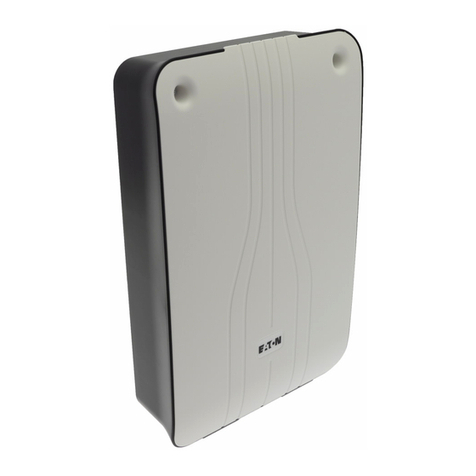
Eaton SDR-REXT User manual

Page 1
SDR-REXT Radio Siren
Installation Guide
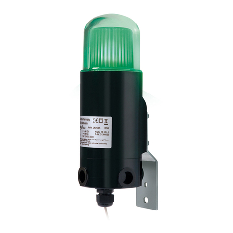
The SDR-REXT is an external siren and strobe unit designed for
use with i-on and Menvier control units. Radio communications
are used between the siren and the control unit, which means that
no fixed wiring between the two is needed.
This product must be installed by qualified service personnel.
Key Features
Easy to install
100 dB(A) sound output
Range of 500m in free space
High-power comfort LEDs
High-power LED strobes
Built-in spirit-level
Self-supporting lid for ease of
installation
Jamming detection
Revolving fixing holes
Engineer (quiet maintenance) mode
Battery voltage monitoring
Lid and rear tamper detection
Selectable cut-off timer
Choice of siren tones
Impact-resistant polycarbonate
construction
Table of Contents
Installing the Siren 1
Quick Reference 3
Installer (Engineer) Mode 4
PCB Jumper Details 4
Set Conf 4
Jam Det 4
Tone 4
Time 4
Comfort LED Operation 4
Fault and Tamper Monitoring 5
Summary of Strobe Operation 5
Maintenance 5
Specifications 5
Installing the Siren
Step 1 –Choose a Location for the Siren
Choose a location that is:
Out of reach of intruders and vandals.
Easily visible for maximum deterrence.
Within radio range of the control
unit/expander (max 500m in free
space). Note: Prior to installation, a
radio signal-strength survey should be
carried out using the optional Eaton
Survey Tool.

Page 2
Do not site the siren:
Within 1m of large metal structures
such as metal doors or frames, water
tanks, fridges and cars.
Within 1m of mains wiring, power
distribution units or metal pipes.
Inside metal enclosures.
Near high-voltage equipment, or near
electronic equipment such as
computers, photocopiers or other radio
devices.
Step 2 –Open the Lid of the Siren
1. With the siren not yet fixed to the wall,
open the hinged cover that gives
access to the lid-retaining screw (see
Figure 2).
2. Loosen the screw and open the lid.
Step 3 –Configure the Siren Jumpers
1. Remove the link/terminal cover (see
Figure 2) by pushing the two retaining
tabs to the side of the unit while lifting
the cover.
2. Set all jumpers in the siren to the
required positions (see Quick
Reference on page 3).
Step 4 –Teach the Control Unit the
Identity of the Siren
1. If not already done, power-up the
control unit. If the siren communicates
through a radio expander, add the radio
expander.
2. Place the siren next to a keypad and also
within range of the radio expander or
control unit that it communicates with.
3. Select: Installer Menu –Detectors/
Devices –External Sirens –Radio
Sirens –Add/Del Siren –<expander> –
<siren address> –Activate Siren
Tamper. Keep this option displayed
while you carry out the next step.
4. Connect both batteries in the siren (see
Figure 1). The control unit should
discover the siren and you should see
"Siren added". If you do not see this, try
again: disconnect the batteries, wait 30
seconds and reconnect.
5. Disconnect the batteries (to prevent a
risk of the siren self-activating). Do not
exit the Installer menu.
Step 5 –Attach the Siren to the Wall
1. Position the siren against the wall using
the built-in spirit level to assist levelling,
and mark all four fixing points.
2. Drill and plug the fixing points using the
screws and plugs provided.
3. Pass wiring through the cable-entry
hole.
4. Screw the siren to the wall. Use the
spirit level and revolving guides to
correct any misalignment.
Step 6 –Power-Up the Siren
Note: The sounder should not activate
during the following process. However, be
prepared in the event that it does
activate; make sure that any very loud
noise produced cannot cause a fall.
1. Re-connect the batteries.
The siren should power up in "silent
startup" mode, which is indicated by the
left-hand comfort LED remaining solidly
lit.
2. The right-hand comfort LED indicates
the state of the comfort LEDs. ON =
comfort LEDs enabled; OFF = comfort
LEDs disabled. To toggle the comfort
LEDs on/off, press the tamper switch
five times.
3. Re-fit the jumper/terminal cover, close
the lid, tighten the lid-retaining screw
and close the screw cover.
Figure 1: Battery
Connector
Page 3
Ten seconds after closing the lid, the
comfort LEDs extinguish, then (if
enabled) flash alternately to show that
the siren is ready. (If you open the lid
again, the siren will self activate.)
4. Fully test the system.
5. Exit the Installer menu. The system is
ready.
Figure 2: SDR-REXT Radio Siren
Quick Reference
Note: See PCB Jumper Details for further information.
Figure 3: Jumpers and Connections
Hinged cover
for lid-retaining
screw
Link/terminal cover
Cover retaining
tab (pull tab
each side to
release cover)
Tamper switch
Spirit level
Battery (1 of 2)
Top fixing hole
Revolving fixing
hole (1 of 3)
Cable entry hole
Time: Choose the sounder cut-off period
Tone: Fit the link or leave open to select the sounder tone
Jam Det: Fit the link to enable
monitoring for jamming
Set Conf: Fit to enable
set/unset confirmation
from the strobe
Bat A/B: Battery connectors

Page 4
Installer (Engineer) Mode
Installer mode activates when you display
the Installer menu at a keypad and
deactivates when you leave the Installer
menu (at every keypad).
Installer mode prevents the sounder and
strobe from activating when the lid is
opened.
When installer mode is activated, both
comfort LEDs switch on continuously for a
few minutes.
PCB Jumper Details
Set Conf
If you want the strobe to make a short-
duration flash when the system is set or
unset, make sure Strobe on Set/Unset is
enabled at the panel, and fit a link across
Set Conf.
The siren ignores a Strobe on Set/Unset
command from the panel if the link is not
fitted. The panel sends the command to all
sirens in the same partition/ward, so you
may want to fit the link on some sirens, but
not others.
Note: Use Strobe on Set/Unset only if there
is a real need. Reducing the number of
commands processed may benefit overall
system performance.
Jam Det
Fit a link across Jam Det (Jam Detection) if
you want the siren to monitor for possible
attempts to jam the radio signal to the
control unit/expander. If jamming is
detected, a "Jamming" message is reported
to the control unit, which may decide to
activate the siren depending on setup.
Note: INCERT certification does not cover
this function.
Note: The System Options –Jamming
option can be set to Off, Fault or Tamper.
Jamming is not reported if Off is selected.
Please refer to the Engineering Guide for
additional information.
Control units, expanders and sirens can
independently monitor for jamming.
Tone
Fit a link across Tone or leave it
disconnected to choose one of two tones
from the sounder. You may want to use this
feature if, for example, you want to be able
to distinguish two sounders that are in close
proximity.
Time
The Time (Cut-Off Timer) jumper
configures the maximum length of time the
sounder operates following an alarm.
Choose 5 seconds, 3 minutes or leave the
link disconnected for a default cut-off time
of 15 minutes.
Comfort LED Operation
If enabled, the comfort LEDs flash
alternately during normal operation when
the siren has power connected to give a
visual indication that the system is
operational.
When installer mode is activated, both
comfort LEDs switch on continuously for a
few minutes. One or both of the comfort
LEDs also switch on continuously during
the silent startup period between
connecting the batteries and 10 seconds
after closing the lid.
The comfort LEDs can be enabled/disabled
during initial power-up (Step 6 on page 2),
or as follows after installation:
a) Enter installer mode at the control unit
(to prevent the siren operating when its
lid is opened).
b) Open the lid of the siren.
c) Unplug the siren batteries.
d) Wait 30 seconds, then follow the
power-up procedure (Step 6 page 2).

Page 5
Fault and Tamper Monitoring
The siren continuously monitors for fault
and tamper conditions and reports any
found to the control unit/expander via the
radio link. The following are monitored:
Tamper switch –The siren's tamper
switch is continuously monitored. The
siren self-activates on a tamper.
Battery voltage –The siren monitors
the battery voltage under load
conditions and reports a fault if the
batteries have approximately one
month of life remaining.
Jamming - If a link is fitted across Jam
Det, the siren monitors for attempted
jamming of the radio signal to the
control unit/expander. See "PCB
Jumper Details".
Summary of Strobe Operation
The strobe operates if the siren self-
activates or if the control unit sends a
command to activate the strobe.
After 15 minutes of the siren being
activated, the strobe flashes at a slower
rate until the alarm is reset.
In i-on/Menvier systems, the strobe can
also be configured using the Set Conf link
and the Strobe on Set/Unset options (see
"PCB Jumper Details").
Maintenance
NOTE: Enter the installer code at a keypad
before opening the lid of the siren. This
should prevent the sounder from activating.
However, be prepared in the event that
the sounder does activate –make sure
that any very loud noise produced
cannot result in a fall.
During routine maintenance, test the siren
for correct operation, check the tamper
switch and for any signs of water or insect
ingress and clean as necessary. Replace
the batteries every two years or as advised
by the control panel (see below). See
Specifications for details of the replacement
battery type needed.
NOTE: Batteries and the unit itself must be
disposed of in accordance with WEEE
regulations and any other local or national
regulations.
NOTE: After removing the existing
batteries, wait 30 seconds before fitting the
new batteries.
To replace the batteries:
1. Enter the installer code at a keypad.
2. Open the hinged cover that gives
access to the lid-retaining screw (see
Figure 2), loosen the screw and open
the lid.
3. Remove the link/terminal cover (see
Figure 2) by pushing the two retaining
tabs to the side of the unit while lifting
the cover.
4. Remove the battery connectors from
the PCB, and remove the batteries.
5. After 30 seconds, insert the new
batteries and connect to the PCB (see
Figure 1).
6. Re-fit the link/terminal cover, close the
lid, tighten the lid-retaining screw and
close the screw cover.
7. Test the system.
Specifications
Type of Warning Device: External, self-
powered
Supply Voltage: 6-7.5V dc; battery low
warning 4.5V
Current Consumption: 0.25mA quiescent
current including comfort LEDs. 225mA
in-alarm current
Sound Output: 100 dB(A)
Radio Frequency: 868.6625MHz narrowband
Radio Power: 10mW
Range: Maximum of 500m in free space
IP Rating: Internal components IP65; Case
IP4X
Strobe Frequency: Double-flash @ approx 1Hz
Case Material: Polycarbonate

Page 6
Intrusion Standards: PD6662:2010,
EN 50131-4:2009,
EN 50131-5-3:2005+A1:2008 (excluding
detection of interference)
Certification Body: ANPI
EN 50131-4 Grade: Grade 2
Environmental Class: Class IV
Battery Type: 2x3V 17Ah Alkaline
Manganese; part number for the set of
two batteries is SDR-R-BAT1.
Battery Life: Typically 2 years.
Weight: 1.2kg (without batteries)
Operating Temperature: -25°C to +60°C
Max Relative Humidity: 95%
Dimensions: 290mm (h) x 277mm (w) x
80mm (d)
SIMPLIFIED EU DECLARATION OF
CONFORMITY
Hereby, Eaton Electrical Products Ltd
declares that the radio equipment type
SDR-REXT is in compliance with Directive
2014/53/EU. The full text of the EU
declaration of conformity is available at the
following internet address:
www.touchpoint-online.com

Page 7
NOTES

Page 8
© Eaton 2017
The information, recommendations, descriptions and
safety notations in this document are based on Eaton
Corporation’s (“Eaton”) experience and judgment and may
not cover all contingencies. If further information is
required, an Eaton sales office should be consulted. Sale
of the product shown in this literature is subject to the
terms and conditions outlined in appropriate Eaton selling
policies or other contractual agreement between Eaton
and the purchaser.
THERE ARE NO UNDERSTANDINGS, AGREEMENTS,
WARRANTIES, EXPRESSED OR IMPLIED, INCLUDING
WARRANTIES OF FITNESS FOR A PARTICULAR
PURPOSE OR MERCHANTABILITY, OTHER THAN
THOSE SPECIFICALLY SET OUT IN ANY EXISTING
CONTRACT BETWEEN THE PARTIES. ANY SUCH
CONTRACT STATES THE ENTIRE OBLIGATION OF
EATON. THE CONTENTS OF THIS DOCUMENT SHALL
NOT BECOME PART OF OR MODIFY ANY CONTRACT
BETWEEN THE PARTIES.
In no event will Eaton be responsible to the purchaser or
user in contract, in tort (including negligence), strict liability
or other-wise for any special, indirect, incidental or
consequential damage or loss whatsoever, including but
not limited to damage or loss of use of equipment, plant or
power system, cost of capital, loss of power, additional
expenses in the use of existing power facilities, or claims
against the purchaser or user by its customers resulting
from the use of the information, recommendations and
descriptions contained herein. The information contained
in this manual is subject to change without notice.
Eaton, Security House, Vantage Point Business Village,
Mitcheldean, GL17 0SZ.
www.touchpoint-online.com
Product Support (UK) Tel: +44 (0) 1594 541978 available
08:30 to 17:00 Monday to Friday.
Part number 12945917 Issue 5, 28/09/17
Table of contents
Other Eaton Security System manuals

Eaton
Eaton i-on16 User manual

Eaton
Eaton FHF DSLB 20 LED User manual

Eaton
Eaton 460-CSA Manual

Eaton
Eaton Menvier 20 User manual

Eaton
Eaton i-on Compact User manual

Eaton
Eaton RTK 725B range User manual

Eaton
Eaton 401-TF Manual

Eaton
Eaton XB11 User manual

Eaton
Eaton BiWire Ultra EF009SB User manual

Eaton
Eaton TWIN LED User manual

Eaton
Eaton DFDAP-M User manual

Eaton
Eaton CU1 Series User manual

Eaton
Eaton 415-TF Manual

Eaton
Eaton MEDC BG2 Exe User manual

Eaton
Eaton MENVIER30 User manual

Eaton
Eaton i-on Style User manual

Eaton
Eaton Activeline GH5 User manual

Eaton
Eaton i-on40H+ User manual

Eaton
Eaton EVT-300 Installation and operation manual

Eaton
Eaton i-on Series User manual