警告表示の意味
注意
・
分解したり内部に触れたりしないでください。
感電の恐れがあります。
・通電中や電源を切った直後は触らないでください。
高温で火傷の恐れがあります。
・端子ネジの締め付けトルクは0.5〜0.6N•mとしてください。
ネジが緩むと発火の恐れがあります。
お願い
(1) 設置・保管環境について
1.温度–25〜+65°C,相対湿度25〜90%で保管してください。
2.高温・高負荷状態(ディレーティング曲線のA部分)では内部素子の劣化・破損を招く恐れ
がありますので使用しないでください。
3.相対湿度25〜85%の場所で使用してください。
4.直射日光の当たる場所では使用しないでください。
5.取り付け加工中に切粉が製品内に入らないようにしてください。
6.製品内に液体や異物、腐食性ガスが入る可能性がある場所では使用しないでください。
7.振動・衝撃の激しい場所では使用しないでください。特にコンタクタなどの装置は振動源に
なりますので、周囲から極力離して設置してください。
8.強い高周波ノイズを発生する機器から離して取り付けてください。
(2)設置・配線について
1.アースは完全に接続してください。アースが不完全な場合、感電の恐れがあります。
2.入出力端子など誤配線のないようご注意ください。発火、破損のおそれがあります。
3.負荷の異常による配線材の発煙・発火を防ぐために下表の線材をご使用ください。
推奨使用線径
4.端子締め付け時に100N以上の力で端子台を押さえつけないでください。
5.通電前には、加工時に覆ったシートなどを必ず取り外して放熱に支障がないことをご確認く
ださい。
(3)出力電圧調整について
出力電圧調整トリマ(V.ADJ)が壊れる恐れがありますので、必要以上に強い力を加えないでく
ださい。
(4)バッテリ充電について
負荷にバッテリを接続される場合は、過電流制限回路及び過電圧保護回路を取り付けてくださ
い。
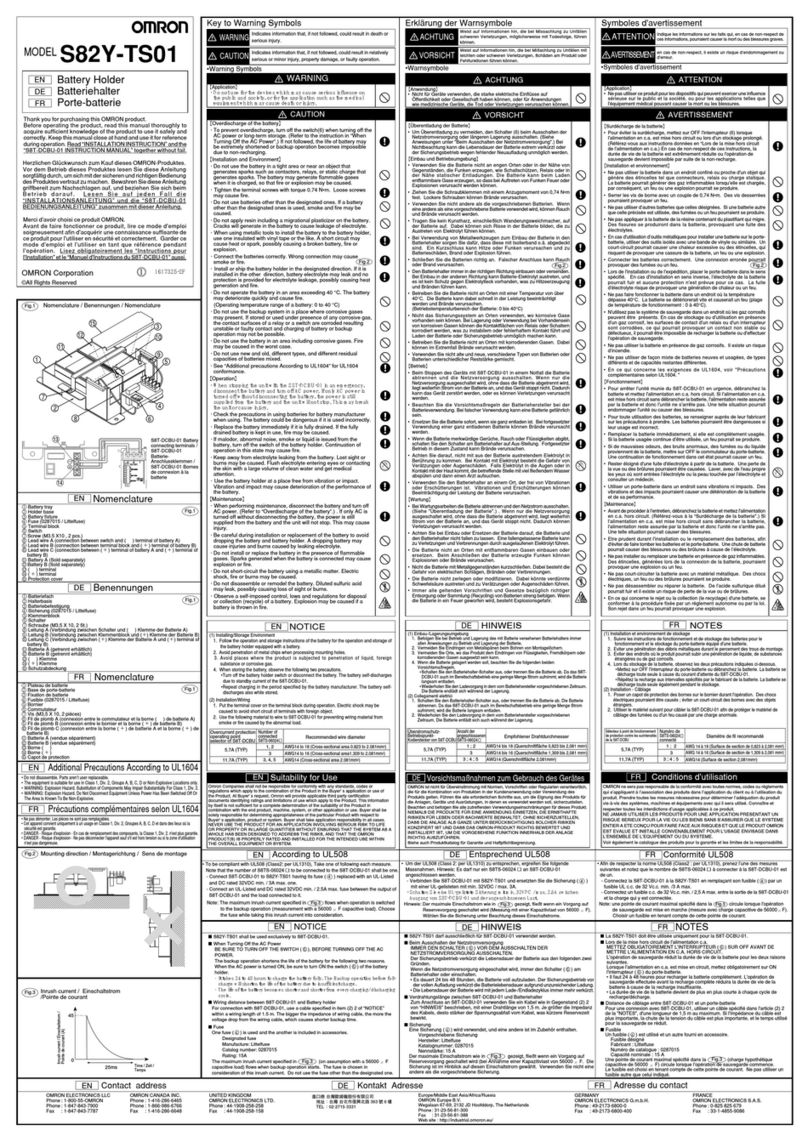
形S8PE-J スイッチング
パワーサプライ
オムロン製品をお買い上げいただきありがとうございます。
この製品を安全に正しく使用していただくために、お使いになる
前にこの取扱説明書をお読みになり、十分にご理解してくださ
い。お読みになった後も、いつも手元に置いてご使用ください。
©All Rights Reserved
取扱説明書
INSTRUCTION MANUAL
・警告表示
注意 誤った取り扱いをすると、障害を負う可能性が想定される場合、および物的損
害の発生が想定される場合を示します。
①–③3相交流入力端子(L1),(L2),(L3)
④グランド(保護アース)端子( )
⑤出力表示灯(DC ON:緑)
⑥出力電圧調整トリマ(V.ADJ)
⑦,⑧直流出力端子(-V),(+V)
各部の名称
次に示すような条件や環境で使用する場合は定格、機能に対して余裕を持った使い方やフェールセイ
フなどの安全対策へのご配慮をいただくとともに、当社営業担当者までご相談くださるようお願いい
たします。
1.取扱説明書に記載のない条件や環境での使用
2.原子力制御・鉄道・航空・車両・燃焼装置・医療機器・娯楽機械・安全機器などへの使用。
3.人命や財産に大きな影響が予想され、特に安全性が要求される用途への使用。
ご使用に際してのお願い
S8PE-J12024CD
S8PE-J24024CD
形式 推奨使用線径
入力線:断面積 1〜2.5mm2
出力線:断面積 4mm2
入力線:断面積 1〜2.5mm2
出力線:断面積 2〜4mm2
JPN
JPN
JPN
JPN
各部の名称/ Nomenclature
Fig. 1
CAUTION
• Do not disassemble the product or touch internal parts.
Electric shock may be caused.
• Do not touch the product during power-on, and immediately after poweroff.
Hot surface may cause heat injury.
• Tighten the terminal screw with torque 0.5 to 0.6 N•m.
A loose screw may cause fire.
(1) Installing/Storage Environment
1.Store the product with ambient temperature –25 to +65°C, and relative humidity 25 to 90%.
2.Do not use the power supply under the high temperature and high load (at the A portion of derating
curve), since the internal components could be deteriorated or broken.
3.Use the product where the relative humidity is 25 to 85%.
4.Avoid places where the product is subjected to direct sun light.
5.Avoid penetration of metal chips when processing mounting holes.
6.Avoid places where the product is subjected to penetration of liquid, foreign substance, or corrosive
gas.
7.Avoid places subject to shock or vibration.
A device such as a contact breaker may be a vibration source. Set the Power Supply as far as possible
from possible sources of shock or vibration.
8.If the Power Supply is used in an area with excessive electronic noise, be sure to separate the Power
Supply as far as possible from the noise sources.
(2) Installation/Wiring
1.Ground the product (PE) completely. Failure to do so could cause electric shock.
2.Ensure that input and output terminals are wired correctly. Otherwise, fire and damage may be caused.
3.Use the following material to the wire to be applied to the product for preventing from the occurrence of
the smoking or ignition caused by the abnormal load.
Recommended Wire Type:
4.Do not apply more than 100N force to the terminal block when tightening it.
5.Be sure to remove the sheet covering the product for machining before power-on.
(3) Output Voltage Adjuster
Do not add unnecessary power. The output voltage adjuster (V.ADJ) may be damaged.
(4) Charging the Battery
If a battery is to be connected as the load, mount an overcurrent limiting circuit and an overvoltage
protection circuit.
CAUTION
Indicates information that, if not followed, could result in relatively
serious or minor injury, property damage, or faulty operation.
• Warning Symbols
Key to Warning Symbols
NOTICE
EN
Precautions in Using the product
When the product is used under the circumstance or environment below, ensure adherence to limitations of the
ratings and functions.
Also take countermeasures for safety precautions such as fail-safe installations.
1.Under the circumstances or environment which are not described in the instruction manual.
2.For nuclear power control, railway, aircraft, vehicle, incinerator, medical equipment, entertainment equipment ,
safety device etc...
3.For applications where death or serious property damage is possible and extensive safety precautions are
required.
EN
S8PE-J12024CD
S8PE-J24024CD
Model Recommended Wire Type
Input terminal : Cross section 1 to 2.5mm2
Output terminal : Cross section 4mm2
Input terminal : Cross section 1 to 2.5mm2
Output terminal : Cross section 2 to 4mm2
EN
Fig. 1
Fig. 3 Fig. 3
1617358-9 A
S8PE-J12024CD S8PE-J24024CD
正しい使い方
ディレーティング曲線 /Derating Curve
Fig. 6
Fig. 3
Fig. 2
Fig. 4
標準取り付け状態 / Normal mounting
■取り付けについて
・取り付け方向
標準取り付け以外で使用しないでください。放熱性悪化により、内部素子が劣化・破壊することがあります。
取り付けにあたっては機器の長期信頼性を向上させるために、放熱に十分留意してください。
自然対流方式ですので、電源ユニット周囲の大気が対流するように取り付けてください。
S8PE-Jを複数台設置される場合は、周囲温度20℃で5cm以上、周囲温度50℃で、10cm 以上の間隔をあけ
てください。
■ディレーティング曲線
注:
1.ディレーティングに問題がある場合は、強制空冷でご使用ください。
2.周囲温度は電源ユニットから50mm下で規定しています。
■入力電圧について
3相 180〜264VAC
注:
入力電源から完全に遮断するためには3相全てをスイッチオフしてください。
■入力欠相について
入力ラインのいずれか1相を欠いた状態(欠相)での運転は電源の内部回路に大きなストレスがかかります
ので、定期的に下記の項目を確認いただき、欠相が発生しないようにしてください。
・入力端子のゆるみやはずれはないか
・入力電圧は規定どおりに印加されているか
・入力電圧に周期的または突発的な欠相、電圧変動が生じていないか
■直列運転、出力電圧(±)
2台の電源で直列運転可能です。また、(±)の出力を作ることもできます。
注:
直列運転は同一仕様の電源で行ってください。
■並列運転
並列運転はできません。
■出力電圧調整について
出荷時:定格電圧にセットしています。
調整範囲:前面の「V.ADJ」(⑥)により22.5V 〜26.4Vの範囲で調整が可能です。
右に回すと出力電圧は上がり、左に回すと出力電圧は下がります。
注:
調整後の出力容量,出力電流は、定格出力容量, 定格出力電流以下にしてください。
■耐電圧試験
電源ユニットの<入力一括①, ② , ③>と<出力⑦, ⑧ , グランド端子④一括>間は 1500VAC 1分間に耐え
るように設計されています。試験を実施する場合、耐電圧試験機のカットオフ電流は20mA に設定して実施
してください。
注:
1.印加電圧は試験機のボリュームで徐々に変化させてください。試験機のスイッチでいきなり 1500V印加ま
たは、遮断するとインパルスが発生し、電源ユニットが破損することがあります。
2.試験時は出力端子は破損防止のため、必ずすべての端子を短絡してください。
■絶縁抵抗試験
絶縁抵抗試験を実施する場合は、DC 絶縁抵抗計(DC500V)をご使用ください。
注:
試験時は出力端子は破損防止のため、必ずすべての端子を短絡してください。
■過電流保護機能
過電流保護回路(定格電流の105% 以上で動作)により、短絡・過電流に対して自動的に出力電圧を低下さ
せ、機器を保護します。過電流状態が解除されると、電源ユニットは自動的に正常運転に復帰します。
注:
1. 20秒以上の短絡、および過電流状態は、内部部品の劣化・破壊を招きますので、避けてください。
2.負荷側の突入電流、過負荷状態が頻繁に発生するアプリケーションには使用しないでください。内部部品
の劣化、破損が考えられます。
■過電圧保護機能
定格出力電圧の約130%以上の電圧を出力した場合、出力電圧を遮断し、過電圧による負荷の破損を防止し
ます。
復帰は入力電源をOFFし、1分以上放置後、入力電源を再投入してください。
注:
入力電源の再投入は、必ず原因を取り除いた後に行ってください。
■出力電圧が出ない場合
過電流保護または、過電圧保護が機能している可能性があります。また、入力に雷サージなどの大きなサー
ジ電圧が印加された場合は、過電圧保護回路が機能している可能性も考えられます。
以下の2点を確認後も出力電圧が出ない場合は、当社までお問い合わせてください。
・過電流保護の確認方法
負荷が過電流状態(短絡含む)になっていないかを(負荷線を外して)確認してください。
・過電圧保護の確認方法
いったん入力電源をOFF し、1分以上放置後、入力電源を再投入してください。
Fig. 5
標準取り付け
その他の取り付け 可
不可
Fig.2
0
20
-10-20 0 10 20 30 40 50 60 70 80
40
60
100
80
負荷率 / Load
周囲温度 /Ambient temperature
120
A
AC(L1)
AC(L2)
AC(L3)
AC(L1)
AC(L2)
AC(L3)
AC(L1)
AC(L3)
AC(L2)
AC(L1)
AC(L2)
AC(L3)
AC(L1)
AC(L2)
AC(L3)
AC(L1)
AC(L2)
AC(L3)
出力電圧(±)
/ Output Voltage (±)
直列運転 / Serial Operation
並列運転 / Parallel Operation
JPN
Thank you for purchasing this OMRON product. This manual
primarily describes precautions required in installing and wiring
the power supply.
Before operating the product, read this manual thoroughly to
acquire sufficient knowledge of the product to use it safely and
correctly. Keep this manual close at hand and use for reference
during operation.
①-③AC input terminals (L1),(L2),(L3)
④Ground terminal (Protective Earth terminal) ( )
⑤Output indicator (DC ON: green)
⑥Output voltage adjuster (V. ADJ)
⑦,⑧DC output terminals (–V), (+V)
Nomenclature
EN
NOTICE
■Mounting
•Mounting Direction
Do not use the product in any way other than the standard mounting direction. Internal components may
deteriorate and be broken due to adverse heat radiation.
Install the power supply so that the air flow circulates around the power supply, as the power supply is designed
to radiate heat by means of natural air flow.
If installing S8PE-J closely, keep the minimum distance of 10 cm at 50 ℃, 5 cm at 20 ℃ambient.
■Derating Curve
Notes:
1.If natural air circulation is limited, use forced air cooling to prevent overheating.
2.The peripheral temperature is specified at the place 50 mm downward from the main body of the power supply.
■Selecting Input Voltage
3-phase 180 to 264 VAC
Note:
In order to switch off the Power Supply completely: all 3 phases need to be switch off.
■Three phase input operation when one phase is missing.
As the loss of one phase puts additional stress on some components, the life span of the unit could be shortened.
It is prudent therefore to regularly check for signs of the following possible conditions.
1. Input terminals wiring open/loose.
2. Incorrect / no voltage on one or more phases of the supply.
3. Abrupt or periodical loss of input voltage.
■Serial Operation and Output Voltage (±)
Two power supplies can be connected in series.
The (±) voltage output can be accomplished with two power supplies.
Notes:
For serial operation, use power supplies with the same specification.
■Parallel Operation
Pararell operation is not possible.
■Output Voltage Adjustment
Default Setting: Set at the rated voltage
Adjustable Range: Adjustable with "V.ADJ "⑥on the front
surface of the product from22.5 V to 26.4 V.
Turning clockwise increases the output voltage, and turning counterclockwise decreases the output voltage.
Notes
Do not exceed the rated output capacity and current after adjusting the output voltage.
■Dielectric Strength Test
Rated dielectric strength:
1500VAC between <input terminals ①,②,③ together > and <output terminals ⑦,⑧,ground terminal ④
together > for 1 minute.
When testing, set the cutoff current for the withstand voltage test device to 20mA.
Notes:
1.Increase / decrease test voltage gradually. Sudden switching of 1500VAC may cause a voltage surge,
damaging the power supply.
2.Be sure to short-circuit all the output terminals of the power supply to protect the power supply from damage.
■Insulation Resistance Test
When testing the insulation resistance of the power supply, use a DC ohmmeter at 500VDC.
Note:
Be sure to short-circuit all the output terminals of the power supply to protect the power supply from damage.
■Overload Protection
The load and the power supply are automatically protected from overcurrent damage by this function.
Overload protection is activated if the output current rises above 105% of the rated current.
When the output current returns within the rated range, overload protection is automatically cleared.
Notes:
1.If the power supply has been short-circuited or supplied with an overcurrent longer than 20 seconds, the
internal parts of the power supply may be deteriorated or damaged.
2.Do not use the product for applications where the load causes frequent inrush current and overload. The
internal parts may be deteriorated or damaged.
■Overvoltage Protection
This power supply automatically protects itself and the load from overvoltage.
Overvoltage protection is activated if the output voltage rises above approx. 130% of the rated output voltage.
To reset the power supply, leave the power supply off for more than 1 minute and then turn it on again.
Note:
Be sure to clear the cause of the overvoltage, before turning on the power supply.
■In Case there is No Output Voltage
The possible cause for no output voltage may be the presence of an overload or overvoltage condition, or may be due
to the functioning of an latching protective device. The overvoltage protection may operate if a large amount of surge
voltage such as a lightening surge occurs while turning on the power supply.
In case there is no output voltage, please check the following points before contacting us:
Check the Overload Protected Status:
• Check whether the load is in overload status or is short-circuited. Remove wires to load when checking.
• Attempt to clear the overvoltage protection function:
Turn the power supply off once, and leave it off for at least 1 minute. Then turn it on again to see if this clears the
condition.
EN
Fig. 1
Fig. 3
Fig. 3
Fig. 5 Fig. 5
Fig. 4 Fig. 4
Fig. 6 Fig. 6
Standard Mounting
Others Mounting Valid
Invalid
Fig.2
24 VDC 5A
50/60Hz 1A
200-230 V 3AC
3 x TH 2A 250V
OUTPUT
INPUT
FUSES INSIDE
INPUT 3AC
POWER SUPPLY
S8PE-J12024CD
L3
L1
L2
V.ADJ
DC ON
OUTPUT 24VDC
-V
+V
24VDC5A
50/60Hz1A
200-230V3AC
3xTH2A250V
OUTPUT
INPUT
FUSESINSIDE
INPUT3AC
POWERSUPPLY
S8PE-J12024CD
L3
L1
L2
V.ADJ
DCON
OUTPUT24VDC
-V
+V
1
2
3
4
5
6
7
8
1
2
3
4
5
6
7
8
L1
L2
L3
POWERSUPPLY
S8PE-J24024CD
-V
+V
OUTPUT24VDC
INPUT3AC
24VDC10A
OUTPUT
50/60Hz2A
200-230V3AC
INPUT
V.ADJ
DCON
3xTH3.15A250V
FUSESINSIDE
お問い合せ先JPN
オムロン株式会社営業統轄事業部
東京都品川区大崎 1-11-1
ゲートシティ大崎ウエストタワー 14F
(〒 141-0032)
Contact address
EN
USA
OMRON ELECTRONICS LLC
Phone: 1-800-55-OMRON
Phone: 1-847-843-7900
CANADA
OMRON CANADA INC.
Phone:1-416-286-6465
Phone:1-514-636-6676(French Language)
EUROPE
OMRON Europe B.V.
Phone : +31 (0)23 56 81 300
制御機器についてのお問い合わせは下記をご利用ください。
三島/TEL 0559-82-5000 東京/ TEL 03-3493-7091
大阪/TEL 06-6253-0471
<地区別に受信いたしますが、回線状況により他地区へ転送させ
て頂くことがあります。>
<電話番号をお確かめの上、正しくダイヤルしてください。>
営業時間:9:00〜12:00 /13:00 〜19:00
営業日:土・日・祝祭日と年末年始・春期と夏期の休業日を除く
FAXによるお問い合わせは下記をご利用ください。
顧客サービスセンタ お客様相談課 FAX 0559-82-5051
インターネットによるお問い合わせは下記をご利用くださ
い。
http://www.fa.omron.co.jp/support/
その他のお問い合わせ先
納期・価格・修理・サンプル・承認図は貴社のお取引先、
または貴社の担当オムロン営業員にご相談ください。
中国
欧姆龍(中国)有限公司
Phone: 86-10-8391-3005
香港
歐姆龍亞洲有限公司
Phone: 852-2375-3827
台灣
台灣歐姆龍股 有限公司
Phone: 886-2-2715-3331
AUSTRALIA
OMRON ELECTRONICS PTY.LTD.
Phone: 02-9878-6377
SINGAPORE
OMRON ASIA-PACIFIC PTE.LTD.
Phone: 65-6835-3011
大韓民国
韓国 OMRON 株式会社
Phone: 82-2-512-0871(Korean)
Phone: 82-2-549-2766(English/Japanese)
