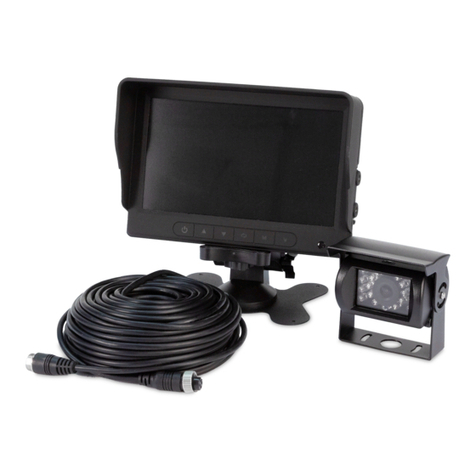
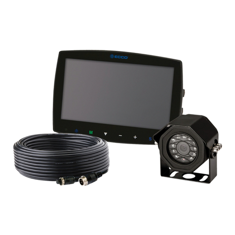
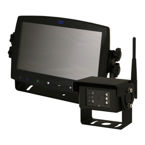
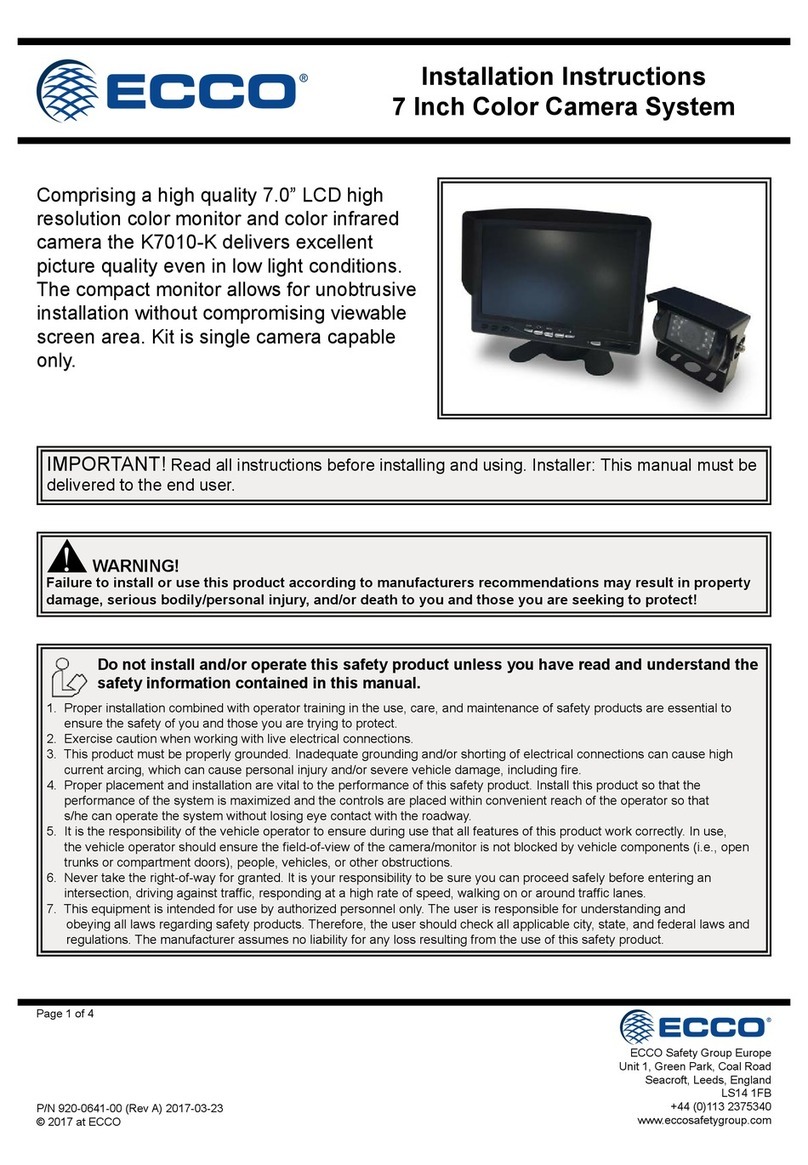
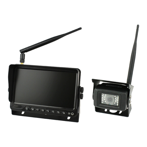
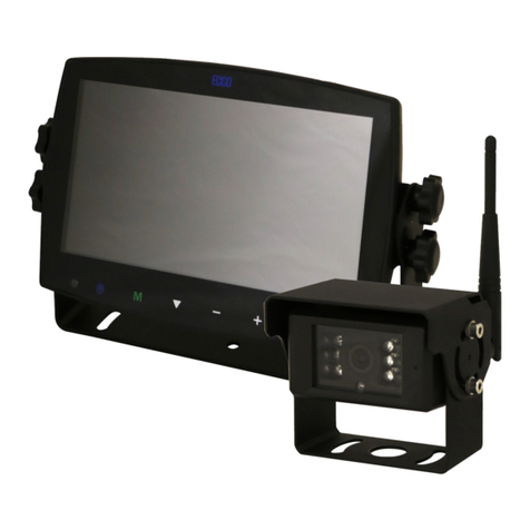
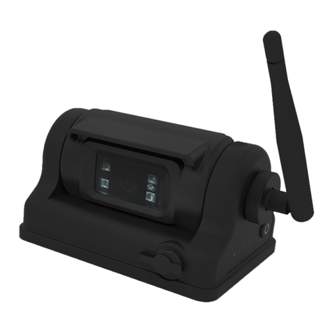
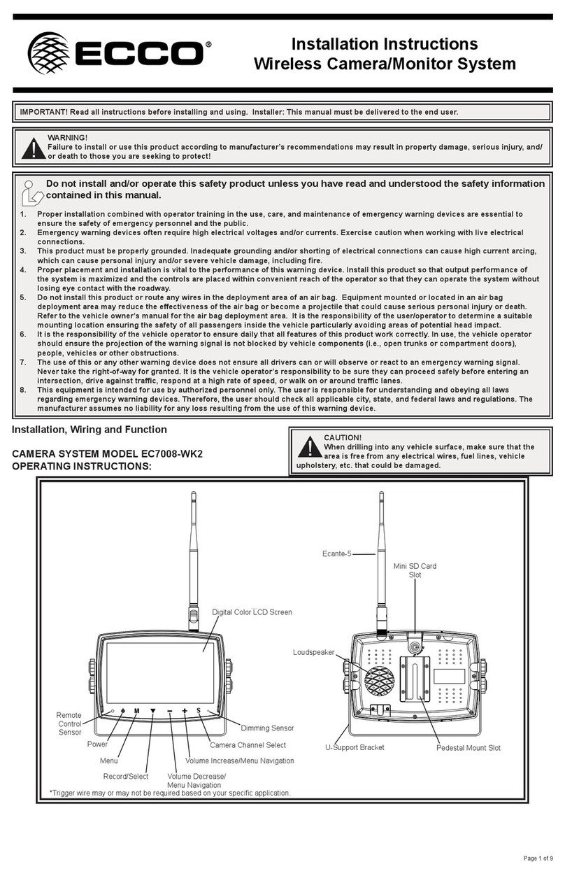
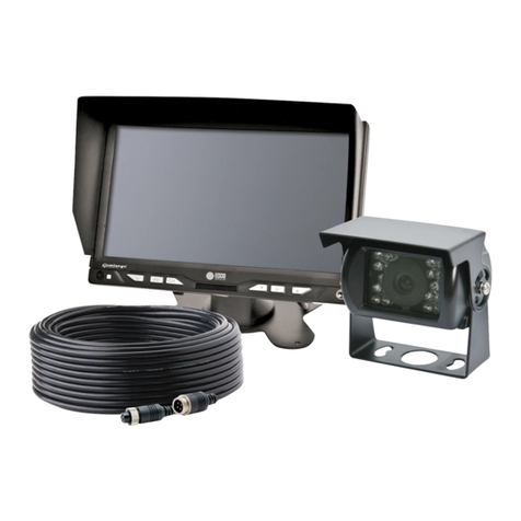
Ecco C2013B-WC Installation instructions

Page 1 of 6
IMPORTANT! Read all instructions before installing and using. Installer: This manual must be delivered to the end user.
WARNING!
Failure to install or use this product according to manufacturer’s recommendations may result in property damage, serious injury, and/
or death to those you are seeking to protect!
Do not install and/or operate this safety product unless you have read and understood the safety information
contained in this manual.
1. Proper installation combined with operator training in the use, care, and maintenance of emergency warning devices are essential to
ensure the safety of emergency personnel and the public.
2. Emergency warning devices often require high electrical voltages and/or currents. Exercise caution when working with live electrical
connections.
3. This product must be properly grounded. Inadequate grounding and/or shorting of electrical connections can cause high current arcing,
which can cause personal injury and/or severe vehicle damage, including ¿re.
4. Proper placement and installation is vital to the performance of this warning device. Install this product so that output performance of
the system is maximized and the controls are placed within convenient reach of the operator so that they can operate the system without
losing eye contact with the roadway.
5. Do not install this product or route any wires in the deployment area of an air bag. Equipment mounted or located in an air bag
deployment area may reduce the eectiveness of the air bag or become a projectile that could cause serious personal injury or death.
Refer to the vehicle owner’s manual for the air bag deployment area. It is the responsibility of the user/operator to determine a suitable
mounting location ensuring the safety of all passengers inside the vehicle particularly avoiding areas of potential head impact.
6. It is the responsibility of the vehicle operator to ensure daily that all features of this product work correctly. In use, the vehicle operator
should ensure the projection of the warning signal is not blocked by vehicle components (i.e., open trunks or compartment doors),
people, vehicles or other obstructions.
7. The use of this or any other warning device does not ensure all drivers can or will observe or react to an emergency warning signal.
Never take the right-of-way for granted. It is the vehicle operator’s responsibility to be sure they can proceed safely before entering an
intersection, drive against trac, respond at a high rate of speed, or walk on or around trac lanes.
8. This equipment is intended for use by authorized personnel only. The user is responsible for understanding and obeying all laws
regarding emergency warning devices. Therefore, the user should check all applicable city, state, and federal laws and regulations. The
manufacturer assumes no liability for any loss resulting from the use of this warning device.
CAUTION!
When drilling into any vehicle surface, make sure that the area is free from any electrical wires, fuel lines, vehicle upholstery, etc. that
could be damaged.
Notes:
1. Larger wires and tight connections will provide longer service life for components. For high current wires it is highly recommended
that terminal blocks or soldered connections be used with shrink tubing to protect the connections. Do not use insulation displacement
connectors (e.g., 3M Scotchlock type connectors).
2. Route wiring using grommets and sealant when passing through compartment walls. Minimize the number of splices to reduce voltage
drop. All wiring should conform to the minimum wire size and other recommendations of the manufacturer and be protected from moving
parts and hot surfaces. Looms, grommets, cable ties, and similar installation hardware should be used to anchor and protect all wiring.
3. Fuses or circuit breakers should be located as close to the power takeo points as possible and properly sized to protect the wiring and
devices.
4. Particular attention should be paid to the location and method of making electrical connections and splices to protect these points from
corrosion and loss of conductivity.
5. Ground termination should only be made to substantial chassis components, preferably directly to the vehicle battery.
6. Circuit breakers are very sensitive to high temperatures and will “false trip” when mounted in hot environments or operated close to their
capacity.
Installation and Operation Instructions
7-inch Wireless Color Camera System
CAUTION!
1. High voltage is present within the monitor. The opening of the case should be by professionals.
2. Do not watch the video while driving unless you are monitoring the rear view camera display.

Page 2 of 6
Camera Model C2013B-WC Installation
1. Find an appropriate location for installation.
2. Drill holes according to the size of U-bracket and x the U-bracket.
3. Drill a 3/4” (19mm) hole next to U-bracket.
4. Install the camera on U-bracket.
5. Loosen the screws on the side of the camera and adjust the camera’s position to get the best view angle in the monitor.
Important! Do not expose the monitor to water, it is not waterproof.
Any water that leaks into the monitor could cause extensive
damage.
Installation and Mounting
Important! Mount the camera at a location that provides the
best view of the area immediately behind the vehicle. Generally,
mounting locations toward the top of the vehicle provide the best
¿eld of view. Lower mounting locations reduce the ¿eld of view and
increase the likelihood of damage from road spray.
Figure 2
Monitor Model M7000B-WM Installation
1. Select suitable position on vehicle and x the bracket support.
2. Fix the monitor to the bracket support and adjust the view angle
3. Connect the monitor to the power harness (provided with kit)
WARNING!
To prevent accidental shock, DO NOT OPEN THE MONITOR
CASE. Opening the monitor case will expose the inside of
the monitor to conditions that could adversely aect performance.
Any evidence of tampering with sealed components will void the
warranty.
Figure 3 - Bracket Installation
Please nd best signal reception position before installation.
The metal body of the vehicle can attenuate wireless signal strength sharply. It is necessary to test the signal
strength before installation.
1. Please connect monitor and camera as detailed in the Wiring Instructions.
2. When pairing the camera to the monitor, please refer to Pairing. Four (4) cameras can be paired
separately to CAM1/CAM2/CAM3/CAM4.
3. Put the monitor and the camera at the intended position to test signal strength.
Figure 1
If you get poor signal reception, or signal cannot reach with 3
bars, please adjust the angle of the antenna to nd the best signal
reception positon.
Good signal
Poor signal
Antenna

Page 3 of 6
Figure 4 - Monitor Parts
Menu Operations
Turn on / o monitor and standby
Increase brightness
Decrease brightness
Function1: OK
Function2: Start / stop recording
Function3: Press button for 3 seconds to switch parking line on / o
Function1: Enter menu or return to previous menu
Function2: Press button for 3 seconds to power on / o audio function
Switch among cameras
Antenna
Digital Color LCD
screen
Power switch
Increase brightness Decrease brightness SELECT
Recording On / O
Menu
Audio On / O
Micro-SD / TF Card
Slot
Channel switch

Page 4 of 6
Important! Waterproof all connections whether inside or outside the vehicle by using sealant and wrapping with insulation tape. Wrap tape
tightly, overlapping by one-half widths so there are no gaps.
Wiring Instructions
Camera Wiring
This is the most commonly used method for users
who have the single camera system (one moni-
tor and one camera). Connect the monitor cable
with the DC connector. Power on the monitor with
cigarette lighter from a 12V vehicle.
Monitor Wiring
Power on the camera by connecting the Red
positive wire to 10 - 32 VDC power source, Black
to Negative / Ground source, and connecting
camera plug.
Pairing
Camera and monitor are paired before factory delivery.
When you need to add or change a camera, please follow the steps below for pairing.
Please nish pairing before installation.
1. Power-on the monitor, press V button to select a Channel(CH1, CH2, CH3, CH4).
2. Under the select channel interface, press Menu button to enter menu interface.
3. Press ▲/+ or ▼/- and OK button to select and enter PAIRING.
4. Press OK button to start and you will have 20 seconds for pairing.
5. Video will be displayed after pairing.
WARNING!
If no picture is displayed after pairing, please retry pairing
steps and power-on again the camera. The pairing must be
completed within 20 seconds, otherwise you need to re-power the
camera for pairing.
Note: To access menu, must be in single camera mode. No menu access in split camera mode.
Reverse light positive (+)

Page 5 of 6
Menu Operation
Power
1. Press Menu button to enter Menu interface.
2. Press ▲/+ or ▼/- to select picture mode, press OK button to enter.
3. Press ▲/+ or ▼/- and OK button to adjust BRIGHTNESS/CONTRAST/HUE/VOLUME.
Mirror
1. Press ▲/+ or ▼/- to select MIRROR setting, press OK to enter.
2. Press ▲/+ or ▼/- and OK button to select NORMAL/MIRROR/FLIP/MIR-FLIP.
Mode
1. Press ▲/+ or ▼/- to select MODE setting, press OK to enter.
2. Press ▲/+ or ▼/- and OK button to select MODE setting, multiple types for optional.

Page 6 of 6
Cam-setup
1. Press ▲/+ or ▼/- and OK to enter CAM-SETUP, you can select the switch status, cycle time, and set automatic cycle of the four cam-
eras.
System Setting
1. Get into the MENU interface, press ▲/+ or ▼/- and OK button to enter SYSTEM setting, under SYSTEM setting menu, you can adjust
the DATE and TIME, LANGUAGE, NTSC/PAL SYSTEM, AUTO-DIM, DELAY/TIME, P-LINE.
Recording
1. Insert SD Card.
2. Please insert SD card in SD card slot, max 128G.
3. Press button to stop / start recording.
Start recording
Monitor top left corner will show and start recording
WARNING!
The ¿rst use of the new card must be formatted in this
machine before it can be used normally.

Page 7 of 9
Play Recorded File
Recorded videos can be played by the monitor.
1. Press ▲/+ or ▼/- and OK button to enter PLAY.
2. Press ▲/+ or ▼/- and OK button to select and play a le.
3. Press OK button to PLAY or PAUSE the le, press MENU key to exit.
Rewrite and Format
Get into RECORD interface, format SD card and loop recording function.
1. Turn on REWRITE function, when the memory card is full, it will automatically clear les and loops the video.
2. Turn o REWRITE function, when the memory card is full, the system will stop recording.
Note: Files must be deleted using a PC.

Page 8 of 9
The symptoms described below do not necessarily mean a failure in the display. Please check the following tiems before you initiate request
for repair.
Symptoms Possible Causes/Solutions
No picture Improper connection of automobile adapter
Use of unauthorized power supply
Power switch is OFF
Please re-pairing the system
No signal Check whether the camera is powered on
Please check whether antennas are plugged on both monitor and camera
Please check the angle of the antenna
Please check whether metal obstacles near the antenna
Please re-pairing the system
No sound Please check whether the monitor with sound function
Check whether the sound is turned o or quad mode display
Dark picture Check whether brightness and contrast are adjusted correctly
No color Re-power the system
Unable to record Please check whether the monitor with record function
Please check whether SD card inserted
Please check whether SD card formatted before recording
Please check whether SD card storage full
The monitor is equipped with Anti-Glare screen. Please remove the screen protector to get best picture after installation.
Troubleshooting
Maintenance
Camera
If dirt, rain, or snow attaches to the camera, the monitor may not clearly display objects. If water droplets, snow, or mud adhere to the cam-
era lens, rinse with water and wipe with a dry cloth.
Do not use alcohol, benzene, or thinner to clear the camera. This will cause discoloration. To clean the camera, wipe with a clean cloth
dampened with mild cleaner diluted with water and then wipe with a dry cloth.
Monitor
Turn o the monitor. If the screen is dark, it will be easier to see the areas that are dirty or oily.
Use a dry, soft cloth and very gently wipe the screen.
If the dry cloth did not completely remove the dirt or oil, do not press harder in an attempt to scrub it o. Pushing directly on the LCD screen
can often cause pixels to burn out.
If necessary, dampen the cloth with distilled water or with an equal ratio of distilled water to white vinegar. The plastic edge that surrounds the
screen can be cleaned with any multipurpose cleaner but take care to avoid contact with the screen itself.
Avoid using paper towels, toilet paper, tissue paper, or something like your shirt to wipe the LCD screen. These non-ultrasoft materials can
easily scratch the screen.
Avoid cleaning products that contain ammonia, ethyl alcohol, acetone, toluene, ethyl acid, or methyl chloride. These chemicals can react with
the materials that the LCD screen is made of which could yellow the screen or cause other kinds of damage.
Never spray liquid directly on the LCD screen or it could run inside the monitor and cause damage.

Page 9 of 9
An ECCO SAFETY GROUP™ Brand
ECCOSAFETYGROUP.com
833 West Diamond St, Boise, Idaho 83705
Customer Service USA 800-635-5900
UK +44 (0)113 237 5340 | AUS +61 (0)3 63322444
ECCOESG.com
Manufacturer Limited Warranty and Limitation of Liability:
Manufacturer warrants that on the date of purchase, this product will conform to Manufacturer’s specications for this product (which are available from the
Manufacturer upon request). This Limited Warranty extends for sixty (60) months from the date of purchase.
DAMAGE TO PARTS OR PRODUCTS RESULTING FROM TAMPERING, ACCIDENT, ABUSE, MISUSE, NEGLIGENCE, UNAPPROVED
MODIFICATIONS, FIRE OR OTHER HAZARD; IMPROPER INSTALLATION OR OPERATION; OR NOT BEING MAINTAINED IN ACCORDANCE WITH
THE MAINTENANCE PROCEDURES SET FORTH IN MANUFACTURER’S INSTALLATION AND OPERATING INSTRUCTIONS VOIDS THIS LIMITED
WARRANTY.
Exclusion of Other Warranties:
MANUFACTURER MAKES NO OTHER WARRANTIES, EXPRESSED OR IMPLIED. THE IMPLIED WARRANTIES FOR MERCHANTABILITY, QUALITY
OR FITNESS FOR A PARTICULAR PURPOSE, OR ARISING FROM A COURSE OF DEALING, USAGE OR TRADE PRACTICE ARE HEREBY
EXCLUDED AND SHALL NOT APPLY TO THE PRODUCT AND ARE HEREBY DISCLAIMED, EXCEPT TO THE EXTENT PROHIBITED BY APPLICABLE
LAW. ORAL STATEMENTS OR REPRESENTATIONS ABOUT THE PRODUCT DO NOT CONSTITUTE WARRANTIES.
Remedies and Limitation of Liability:
MANUFACTURER’S SOLE LIABILITY AND BUYER’S EXCLUSIVE REMEDY IN CONTRACT, TORT (INCLUDING NEGLIGENCE), OR UNDER ANY
OTHER THEORY AGAINST MANUFACTURER REGARDING THE PRODUCT AND ITS USE SHALL BE, AT MANUFACTURER’S DISCRETION,
THE REPLACEMENT OR REPAIR OF THE PRODUCT, OR THE REFUND OF THE PURCHASE PRICE PAID BY BUYER FOR NON-CONFORMING
PRODUCT. IN NO EVENT SHALL MANUFACTURER’S LIABILITY ARISING OUT OF THIS LIMITED WARRANTY OR ANY OTHER CLAIM RELATED TO
THE MANUFACTURER’S PRODUCTS EXCEED THE AMOUNT PAID FOR THE PRODUCT BY BUYER AT THE TIME OF THE ORIGINAL PURCHASE.
IN NO EVENT SHALL MANUFACTURER BE LIABLE FOR LOST PROFITS, THE COST OF SUBSTITUTE EQUIPMENT OR LABOR, PROPERTY
DAMAGE, OR OTHER SPECIAL, CONSEQUENTIAL, OR INCIDENTAL DAMAGES BASED UPON ANY CLAIM FOR BREACH OF CONTRACT,
IMPROPER INSTALLATION, NEGLIGENCE, OR OTHER CLAIM, EVEN IF MANUFACTURER OR A MANUFACTURER’S REPRESENTATIVE HAS BEEN
ADVISED OF THE POSSIBILITY OF SUCH DAMAGES. MANUFACTURER SHALL HAVE NO FURTHER OBLIGATION OR LIABILITY WITH RESPECT
TO THE PRODUCT OR ITS SALE, OPERATION AND USE, AND MANUFACTURER NEITHER ASSUMES NOR AUTHORIZES THE ASSUMPTION OF
ANY OTHER OBLIGATION OR LIABILITY IN CONNECTION WITH SUCH PRODUCT.
This Limited Warranty denes specic legal rights. You may have other legal rights which vary from jurisdiction to jurisdiction. Some jurisdictions do not
allow the exclusion or limitation of incidental or consequential damages.
© 2022 ECCO, Inc. All rights reserved.
920-0985-00 Rev. B

Página 1 de 9
Sistema de cámara a color inalámbrica
de 7 pulgadas
Instrucciones de instalación y operación
¡ADVERTENCIA!
Si no sigue las instrucciones del fabricante a la hora de instalar o usar el producto, pueden producirse daños materiales, y lesiones
graves o incluso mortales a aquellos que pretende proteger!
No instale ni opere este producto de seguridad, a menos que haya leído y comprendido la información de
seguridad contenida en este manual.
1. Para garantizar su propia seguridad y la de las personas a las que intenta proteger, es esencial una instalación correcta, combinada con
la formación de operador en el uso, cuidado y mantenimiento de los dispositivos de alerta de emergencia.
2. Los dispositivos de advertencia de emergencia a menudo requieren altos voltajes y/o corrientes eléctricas. Tenga cuidado cuando
manipule conexiones eléctricas con corriente.
3. Este producto debe estar conectado a tierra correctamente. Una conexión a tierra incorrecta o unas conexiones eléctricas
cortocircuitadas pueden provocar arcos de corriente alta, lo que puede ocasionar lesiones personales o daños graves en el vehículo,
incluso un incendio.
4. La colocación e instalación adecuadas son vitales para el buen funcionamiento de este dispositivo de alarma. Instale este producto
de forma que permita un rendimiento óptimo del sistema y los controles estén situados de modo que el operador pueda alcanzarlos
cómodamente y manejar el sistema sin perder en ningún momento el contacto visual con la calzada.
5. No instale este producto ni coloque los cables en la zona de despliegue de un airbag. Si el equipo se monta o coloca en la zona de
despliegue de un airbag, el airbag perderá e¿cacia o el equipo puede salir despedido, lo cual puede causar lesiones graves o incluso
mortales. Consulte el manual del propietario del vehículo para conocer la zona de despliegue de los airbags. El usuario u operador son
responsables de determinar una posición de montaje adecuada que garantice la seguridad de todos los ocupantes del vehículo, y deben
evitar zonas que puedan provocar golpes en la cabeza.
6. Es responsabilidad del operador del vehículo asegurarse de que todas las características de este producto funcionan correctamente
durante su uso. Durante su uso, el operador del vehículo debe asegurarse de que no haya componentes del vehículo (como los maleteros
o puertas del habitáculo abiertos), personas, vehículos u otros obstáculos que bloqueen la señal de alarma.
7. El uso de este o cualquier otro dispositivo de alarma no garantiza que los conductores puedan o quieran observar o reaccionar a la señal
de alarma. Nunca dé por hecho que tiene prioridad de paso. Es responsabilidad enteramente suya asegurarse de que puede continuar
de forma segura antes de entrar en una intersección, conducir en sentido contrario, responder a una gran velocidad o caminar por los
carriles de trá¿co o cerca de ellos.
8. El uso de este equipo está destinado exclusivamente a personal autorizado. El usuario es responsable de conocer y acatar todas las
leyes vigentes relacionadas con dispositivos de señales de advertencia. Por lo tanto, el usuario debe comprobar todas las leyes y
normativas de ámbito metropolitano, regional, nacional y cualquier otro ámbito pertinente. El fabricante no asume responsabilidad alguna
por pérdidas derivadas del uso de este dispositivo de alarma.
¡IMPORTANTE! Lea todas las instrucciones antes de instalar y utilizar. Instalador: Este manual se debe entregar al usuario ¿nal.
Notas:
1. Los cables más largos y las conexiones bien ajustadas ofrecerán una mayor vida útil a los componentes. Para cables de alta corriente, se
recomienda usar bloques de terminales o conexiones soldadas cuando se intube por contracción para proteger las conexiones. No usa
conectores de por desplazamiento en aislamiento (p. ej., conectores tipo Scotchlock de 3M)
2. Enrute el cableado utilizando pasacables y sellante cuando atraviese las paredes del compartimiento. Minimice el número de empalmes
para reducir la caída de tensión. Las temperaturas ambiente altas (p. ej., debajo de la cajuela) reducirán signi¿cativamente la capacidad
de transmisión de la corriente de cables, fusibles e interruptores. Todo el cableado debe estar en conformidad con el tamaño mínimo de
cable y otras recomendaciones del fabricante, además de estar protegido de las partes móviles y las super¿cies calientes. Deben usarse
mangueras, pasacables, amarres de cables y accesorios similares de instalación para anclar y proteger todo el cableado.
3. Los fusibles o interruptores deben ubicarse tan cerca de los puntos de toma de potencia como sea posible y deben ajustarse al tamaño
exacto para proteger el cableado y los dispositivos.
4. Se debe prestar atención especial a la ubicación y al método para hacer las conexiones eléctricas y empalmes para proteger estos puntos
de la corrosión y la pérdida de conductividad.
5. La puesta a tierra solo debe hacerse a componentes sustanciales del chasis, de preferencia directamente a la batería del vehículo.
6. Los interruptores son muy sensibles a altas temperaturas y “se desconectarán falsamente” cuando se monten en ambientes calientes o
se operen cerca de su capacidad.
¡PRECAUCIÓN!
Al perforar cualquier super¿cie del vehículo, asegúrese de que no haya cables eléctricos, mangueras de combustible, tapicería, etc. en
el área que pudiesen dañarse.
¡PRECAUCIÓN!
1. Hay alto voltaje dentro del monitor. La apertura de la carcasa debe estar a cargo de profesionales.
2. No mire el video mientras conduce a menos que esté monitoreando la pantalla de la cámara retrovisora.
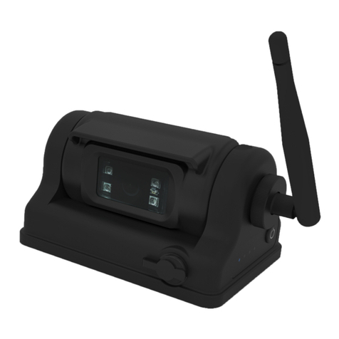
Página 2 de 9
Instalación y montaje
Busque la mejor posición de recepción de señal antes de la instalación.
El chasis de metal del vehículo puede atenuar considerablemente la intensidad de la señal inalámbrica. Debe
probarse la intensidad de la señal antes de la instalación.
1. Conecte el monitor y la cámara como se detalla en las Instrucciones de cableado.
2. Para vincular la cámara con el monitor, consulte Vinculación. Se pueden vincular cuatro (4) cámaras por
separado a CAM1/CAM2/CAM3/CAM4.
3. Coloque el monitor y la cámara en la posición prevista para probar la intensidad de la señal.
Antena Si obtiene una mala recepción de la señal o la señal no puede
alcanzar las 3 barras, ajuste el ángulo de la antena para encontrar
la mejor posición de recepción de la señal.
Señal buena
Señal débil
Instalación de la cámara modelo C2013B-WC
1. Busque una ubicación apropiada para la instalación.
2. Perfore oricios de acuerdo con el tamaño del soporte en U y fíjelo.
3. Perfore un oricio de 19 mm (3/4”) junto al soporte en U.
4. Instale la cámara en el soporte en U.
5. Aoje los tornillos en el costado de la cámara y ajuste la posición
de la cámara para obtener el mejor ángulo de visión en el monitor.
¡Importante! No exponga el monitor al agua, ya que no es
resistente al agua. Cualquier ¿ltración de agua al interior del
monitor podría causar daños importantes.
¡Importante! Monte la cámara en el lugar que proporcione la
mejor vista del área situada inmediatamente detrás del vehículo.
Generalmente, las ubicaciones de montaje hacia la parte superior
del vehículo brindan el mejor campo de visión. Las ubicaciones
de montaje más bajas reducen el campo de visión y aumentan la
probabilidad de daños por rocío proveniente de la carretera.
Figura 2
Instalación del monitor modelo M7000B-WM
1. Seleccione la posición adecuada en el vehículo y je la base del soporte.
2. Fije el monitor a la base del soporte y ajuste el ángulo de visión.
3. Conecte el monitor a los cables de alimentación (incluidos en el kit).
¡ADVERTENCIA!
Para evitar descargas accidentales, NO ABRA LA
CARCASA DEL MONITOR. Abrir la carcasa del monitor
expondrá el interior del monitor a condiciones que podrían
afectar negativamente el rendimiento. Cualquier evidencia de
manipulación de los componentes sellados anulará la garantía.
Figura 3: Instalación del soporte
Figura 1

Página 3 de 9
Figura 4: Partes del monitor
Operaciones del menú
Encender/apagar monitor y modo de espera
Aumentar brillo
Disminuir brillo
Función 1: aceptar
Función 2: iniciar/detener la grabación
Función 3: presionar el botón durante 3 segundos para encender/apa-
gar la línea de estacionamiento
Función 1: entrar en el menú o volver al menú anterior
Función 2: presionar el botón durante 3 segundos para encender/apa-
gar la función de audio
Cambiar entre cámaras
Antena
Pantalla LCD digital
a color
Interruptor de alimen-
tación
Aumentar brillo Disminuir brillo
SELECCIONAR
Encendido/apagado
de grabación
Menú
Encendido/apagado
de audio
Ranura para tarjeta
MicroSD o TF
Cambio de canal

Página 4 de 9
¡Importante! Impermeabilice todas las conexiones, ya sea dentro o fuera del vehículo, usando sellador y envolviéndolas con cinta aislante.
Coloque la cinta ¿rmemente y superpóngala por mitades del ancho para que no queden espacios.
Instrucciones de cableado
Cableado de la cámara
Este es el método más utilizado por los usuarios que tienen el
sistema de cámara individual (un monitor y una cámara). Conecte
el cable del monitor con el conector de CC. Encienda el monitor con
encendedor de cigarrillos de un vehículo de 12 V.
Cableado del monitor
Encienda la cámara conectando el cable rojo
positivo a una fuente de alimentación de 10 a
32 V CC y el negro a la fuente negativa/tierra, y
enchufe la cámara.
Vinculación
La cámara y el monitor se vinculan antes de la entrega de fábrica.
Cuando necesite agregar o cambiar una cámara, siga los pasos a continuación para la vinculación.
Finalice la vinculación antes de la instalación.
1. Encienda el monitor y presione el botón V para seleccionar un canal (CH1, CH2, CH3, CH4).
2. En la interfaz de selección de canales, presione el botón Menú para ingresar a la interfaz del menú.
3. Presione ▲/+ o ▼/- y el botón Aceptar para seleccionar e ingresar a VINCULACIÓN.
4. Presione el botón Aceptar para comenzar y tendrá 20 segundos para realizar la vinculación.
5. El video se mostrará después de la vinculación.
¡ADVERTENCIA!
Si no se muestra ninguna imagen después de la
vinculación, vuelva a intentar los pasos de vinculación y
vuelva a encender la cámara. La vinculación debe completarse en
20 segundos; de lo contrario, deberá volver a encender la cámara
para poder realizarla.
Nota: Para acceder al menú, debe estar en el modo de cámara individual. Sin acceso al menú en el modo de cámara dividida.
Positivo (+) de luz de marcha atrás
Positivo (+) de luz de mar-
cha atrás

Página 5 de 9
Operación del menú
Encendido
1. Presione el botón Menú para acceder a la interfaz de menú.
2. Presione ▲/+ o ▼/- para seleccionar el modo de imagen, presione el botón Aceptar para ingresar.
3. Presione ▲/+ o ▼/- y el botón Aceptar para ajustar el brillo (BRIGHTNESS), contraste (CONTRAST), tono (HUE) o volumen (VOLU-
ME).
Espejo
1. Presione ▲/+ o ▼/- para seleccionar la conguración del espejo (MIRROR), presione Aceptar para ingresar.
2. Presione ▲/+ o ▼/- y el botón Aceptar para seleccionar normal (NORMAL), espejo (MIRROR), invertir (FLIP) o invertir espejo (MIR-
FLIP).
Modo
1. Presione ▲/+ o ▼/- para seleccionar la conguración del modo (MODE), presione Aceptar para ingresar.
2. Presione ▲/+ o ▼/- y el botón Aceptar para seleccionar la conguración del modo (MODE), varios tipos opcionales.

Página 6 de 9
Con¿guración de cámara
1. Presione ▲/+ o ▼/- y Aceptar para ingresar a la conguración de la cámara (CAM-SETUP). Puede seleccionar el estado del interruptor,
el tiempo del ciclo y congurar el ciclo automático de las cuatro cámaras.
Con¿guración del sistema
1. Ingrese a la interfaz de MENÚ, presione ▲/+ o ▼/- y el botón Aceptar para ingresar a la conguración del sistema (SYSTEM). Allí pue-
de ajustar las opciones de fecha y hora (DATE AND TIME), idioma (LANGUAGE), sistema NTSC/PAL (NTSC/PAL SYSTEM), atenua-
ción automática (AUTO-DIM), retardo/tiempo (DELAY/TIME) y línea P (P-LINE).
Grabación
1. Inserte la tarjeta SD.
2. Inserte la tarjeta SD en la ranura para tarjeta SD (128 Gb como máximo).
3. Presione el botón para detener/iniciar la grabación.
Empezar a grabar
Se mostrará la esquina superior izquierda del monitor y
comenzará la grabación
¡ADVERTENCIA!
Al usar por primera vez la nueva tarjeta, debe formatearse
en esta máquina para que pueda usarse normalmente.

Página 7 de 9
Reproducir archivo grabado
El monitor puede reproducir los videos grabados.
1. Presione ▲/+ o ▼/- y el botón Aceptar para seleccionar Reproducir (PLAY).
2. Presione ▲/+ o ▼/- y el botón Aceptar para seleccionar y reproducir un archivo.
3. Presione el botón Aceptar para reproducir o pausar el archivo, presione Menú para salir.
Reescribir y formatear
Ingrese a la interfaz de grabar (RECORD), formatee la tarjeta SD y active la función de grabación en bucle.
1. Active la función de reescribir (REWRITE). Cuando la tarjeta de memoria esté llena, borrará automáticamente los archivos y reproducirá
el video en bucle.
2. Apague a función de reescribir (REWRITE). Cuando la tarjeta de memoria esté llena, el sistema dejará de grabar.
Nota: Los archivos se deben eliminar en una PC.

Página 8 de 9
Los síntomas descritos a continuación no necesariamente signican una falla en la pantalla. Verique los siguientes elementos antes de
iniciar la solicitud de reparación.
Síntomas Posibles causas/soluciones
No hay imagen Conexión incorrecta del adaptador del automóvil
Uso de fuente de alimentación no autorizada
El interruptor de alimentación está APAGADO
Vuelva a vincular el sistema
No hay señal Compruebe si la cámara está encendida
Compruebe si las antenas están conectadas tanto en el monitor como en
la cámara
Compruebe el ángulo de la antena
Compruebe si hay obstáculos metálicos cerca de la antena
Vuelva a vincular el sistema
No hay sonido Compruebe la función de sonido del monitor
Compruebe si el sonido está apagado o si se muestra en modo cuádruple
Imagen oscura Compruebe si el brillo y el contraste están ajustados correctamente
Imagen en blanco
y negro
Vuelva a encender el sistema
No se puede
grabar
Compruebe la función de grabación del monitor
Verique si la tarjeta SD está insertada
Verique si la tarjeta SD está formateada antes de grabar
Compruebe si el almacenamiento de la tarjeta SD está lleno
El monitor está equipado con una pantalla antirreectante. Retire el protector de pantalla para obtener la mejor imagen después de la
instalación.
Resolución de problemas
Mantenimiento
Cámara
Si se adhiere suciedad, lluvia o nieve a la cámara, es posible que el monitor no muestre claramente los objetos. Si se adhieren gotas de
agua, nieve o barro al lente de la cámara, enjuague con agua y limpie con un paño seco.
No utilice alcohol, bencina ni solventes para limpiar la cámara. Esto causará decoloración. Para limpiar la cámara, use un paño limpio
humedecido con un limpiador suave diluido en agua y luego un paño seco.
Monitor
Apague el monitor. Si la pantalla está oscura, será más fácil ver las áreas sucias o aceitosas.
Utilice un paño seco y suave y limpie la pantalla con mucha delicadeza.
Si el paño seco no eliminó por completo la suciedad o el aceite, no presione con más fuerza para intentar restregarlo. Presionar directamen-
te sobre la pantalla LCD a menudo puede hacer que los píxeles se quemen.
Si es necesario, humedezca el paño con agua destilada o con una proporción igual de agua destilada y vinagre blanco. El borde de plástico
que rodea la pantalla se puede limpiar con cualquier limpiador multiuso, pero tenga cuidado de evitar el contacto con la pantalla en sí.
Evite usar toallas de papel, papel higiénico, papel tisú o algo como su camisa para limpiar la pantalla LCD. Estos materiales no ultrasuaves
pueden rayar fácilmente la pantalla.
Evite los productos de limpieza que contengan amoníaco, alcohol etílico, acetona, tolueno, ácido etílico o cloruro de metilo. Estos productos
químicos pueden reaccionar con los materiales de los que está hecha la pantalla LCD, lo que podría volverla amarillenta o causar otro tipo
de daños.
Nunca rocíe líquido directamente sobre la pantalla LCD ya que podría ingresar al monitor y causar daños.

Página 9 de 9
Limitación de responsabilidad y garantía limitada del fabricante:
El fabricante garantiza que al momento de la compra, este producto cumple con las especicaciones del fabricante para el mismo (disponibles a
pedido). El fabricante garantiza además que el presente producto está libre de defectos en sus materiales y en su fabricación. Esta garantía limitada
se extiende durante sesenta (60) meses a partir de la fecha de la compra. Pueden aplicarse otras garantías. Para más información, comuníquese
con el fabricante. El fabricante, a criterio propio, reparará o cambiará todo producto que determine como defectuoso y que esté sujeto a la presente
garantía limitada.
EL DAÑO A LAS PIEZAS O PRODUCTOS QUE RESULTE DE LA MANIPULACIÓN INDEBIDA, ACCIDENTES, ABUSO, USO INDEBIDO,
NEGLIGENCIA, MODIFICACIONES NO APROBADAS, INCENDIOS U OTROS PELIGROS, LA INSTALACIÓN O EL USO INCORRECTOS O LA
FALTA DE MANTENIMIENTO CONFORME A LOS PROCEDIMIENTOS DE MANTENIMIENTO QUE SE ESTABLECEN EN LAS INSTRUCCIONES DE
INSTALACIÓN Y USO DEL FABRICANTE, ANULA LA PRESENTE GARANTÍA LIMITADA.
LAS REPRESENTACIONES O DESCRIPCIONES ORALES DEL PRODUCTO QUE PUEDAN HABER SIDO REALIZADAS POR VENDEDORES,
DISTRIBUIDORES, AGENTES U OTROS REPRESENTANTES DEL FABRICANTE NO CONSTITUYEN GARANTÍAS. ESTA GARANTÍA LIMITADA NO
PODRÁ ENMENDARSE, MODIFICARSE NI AMPLIARSE EXCEPTO MEDIANTE UN ACUERDO ESCRITO FIRMADO POR UN REPRESENTANTE
AUTORIZADO DEL FABRICANTE QUE HAGA REFERENCIA EN FORMA EXPRESA A ELLA.
Exclusión de otras garantías:
EL FABRICANTE NO OTORGA NINGUNA OTRA GARANTÍA, EXPRESA O IMPLÍCITA. MEDIANTE LA PRESENTE, SE EXCLUYEN LAS GARANTÍAS
IMPLÍCITAS DE COMERCIABILIDAD O APTITUD PARA UN PROPÓSITO EN PARTICULAR, QUE NO SE APLICARÁN AL PRODUCTO. EL ÚNICO Y
EXCLUSIVO REMEDIO DEL COMPRADOR CON RESPECTO AL CONTRATO, DERECHOS POR DAÑOS O CUALQUIER OTRA TEORÍA CONTRA
EL FABRICANTE RELACIONADA CON EL PRODUCTO Y SU USO SERÁ LA REPARACIÓN O EL REEMPLAZO DEL PRODUCTO SEGÚN SE
DESCRIBE ANTERIORMENTE.
Limitación de responsabilidad:
EN EL CASO DE RESPONSABILIDAD POR DAÑOS QUE SURJAN DE LA PRESENTE GARANTÍA LIMITADA O POR CUALQUIER OTRO
RECLAMO RELACIONADO CON LOS PRODUCTOS DEL FABRICANTE, CON LA RESPONSABILIDAD DEL FABRICANTE FRENTE A LOS DAÑOS,
QUEDARÁ LIMITADA AL IMPORTE PAGADO POR EL PRODUCTO EN EL MOMENTO DE LA COMPRA ORIGINAL. EL FABRICANTE NO SERÁ
RESPONSABLE, BAJO NINGÚN MOTIVO, POR EL LUCRO CESANTE, EL COSTO DE LA MANO DE OBRA NI DEL EQUIPO DE SUSTITUCIÓN,
DAÑOS A LA PROPIEDAD NI POR OTROS DAÑOS ESPECIALES, RESULTANTES O INDIRECTOS EN FUNCIÓN DE RECLAMOS POR
INCUMPLIMIENTO CONTRACTUAL, INSTALACIÓN INAPROPIADA, NEGLIGENCIA U OTROS, INCLUSO SI EL FABRICANTE O UNO DE SUS
REPRESENTANTES HUBIESE ANTICIPADO LA POSIBILIDAD DE DICHOS DAÑOS. EL FABRICANTE NO TENDRÁ NINGUNA OTRA OBLIGACIÓN
O RESPONSABILIDAD RESPECTO DEL PRODUCTO O SU VENTA, OPERACIÓN Y USO NI SUPONE O AUTORIZA QUE SE SUPONGA TODA
OTRA OBLIGACIÓN O RESPONSABILIDAD RELACIONADAS CON DICHO PRODUCTO.
Esta garantía limitada dene los derechos legales especícos. Es posible que tenga otros derechos legales que varían de estado a estado. Algunos
estados no permiten la exclusión o limitación de daños resultantes o indirectos.
© 2022 ECCO, Inc. Todos los derechos reservados.
920-0985-00 Rev. B
Unit 1, Green Park, Coal Road
Seacroft, Leeds, England LS14 1FB
+44 (0)113 2375340
ECCOESG.co.uk
An ECCO SAFETY GROUP™ Brand
ECCOSAFETYGROUP.com
833 West Diamond Street
Boise, Idaho 83705
800-635-5900
ECCOESG.com

Page 1 sur 9
Système de caméra couleur sans ¿l de
7 pouces
Instructions d’installation et d’utilisation
IMPORTANT! Lisez toutes les instructions avant d’installer et d’utiliser le produit. Installateur : ce manuel doit être remis à l’utilisateur ¿nal.
AVERTISSEMENT!
Le non-respect des recommandations du fabricant au cours de l’installation ou de l’utilisation de ce produit peut entraîner des
dommages matériels et causer à ceux que vous souhaitez protéger des blessures graves, voire mortelles!
N’installez pas et/ou n’utilisez pas ce produit de sécurité avant d’avoir lu et compris les consignes de
sécurité fournies.
1. Pour garantir votre sécurité et celle des autres, il est essentiel que le produit soit correctement installé et que l’opérateur soit formé à
l’utilisation, l’entretien et la maintenance des dispositifs d’avertissement d’urgence.
2. Les dispositifs d’avertissement d’urgence nécessitent souvent des tensions et/ou des courants électriques élevés. Manipulez les
connexions électriques sous tension avec prudence.
3. Ce produit doit être correctement mis à la masse. Une mise à la masse inadéquate ou un court-circuit des connexions électriques peut
provoquer l’apparition d’un arc électrique haute tension, susceptible de causer des blessures corporelles ou des dommages graves sur le
véhicule, ainsi qu’un incendie.
4. Une installation et un positionnement corrects sont essentiels au bon fonctionnement de ce dispositif d’avertissement. Installez ce
produit de manière à optimiser les performances de sortie du système et de sorte que les commandes soient à portée de main de
l’opérateur, a¿n qu’il puisse utiliser le système sans perdre le contact visuel avec la chaussée.
5. N’installez pas ce produit dans la zone de déploiement d’un airbag ; n’acheminez pas non plus de câbles dans cette zone. Tout
équipement monté ou situé dans la zone de déploiement d’un airbag est susceptible de réduire l’ecacité de cet airbag ou de devenir
un projectile pouvant causer des blessures graves, voire mortelles. Reportez-vous au manuel d’utilisation du véhicule pour en savoir
davantage sur la zone de déploiement de l’airbag. Il incombe à l’utilisateur/à l’opérateur de dé¿nir un emplacement de montage approprié
assurant la sécurité de tous les passagers à l’intérieur du véhicule, en évitant en particulier les zones d’impact potentiel de la tête.
6. Il incombe à l’opérateur du véhicule de s’assurer que toutes les fonctionnalités de ce produit fonctionnent correctement au cours de
l’utilisation. Lorsque le produit est en cours d’utilisation, l’opérateur du véhicule doit s’assurer que le signal d’avertissement n’est pas
inhibé par des composants du véhicule (comme un core ou des portes de compartiment ouverts), des personnes, des véhicules ou
d’autres éléments.
7. L’utilisation de ce dispositif d’avertissement ou de tout autre dispositif similaire ne garantit pas que tous les conducteurs observeront
un signal d’avertissement ou réagiront à ce signal. Ne prenez jamais la priorité pour acquise. Il est de votre responsabilité de vous
assurer que vous pouvez vous déplacer en toute sécurité avant de vous engager dans une intersection, de conduire en sens inverse de la
circulation, de réagir à une vitesse élevée et de marcher sur ou autour des voies de circulation.
8. Cet équipement est destiné uniquement au personnel autorisé. Il incombe à l’utilisateur de comprendre et de respecter toutes les
lois relatives aux dispositifs de signalisation d’avertissement. Par conséquent, l’utilisateur doit s’informer sur toutes les lois et
réglementations en vigueur dans la ville, la région et le pays où il se trouve. Le fabricant décline toute responsabilité en cas de perte
découlant de l’utilisation de ce dispositif d’avertissement.
¡PRECAUCIÓN!
Al perforar cualquier super¿cie del vehículo, asegúrese de que no haya cables eléctricos, mangueras de combustible, tapicería, etc. en
el área que pudiesen dañarse.
Remarques:
1. Des câbles plus gros et des connexions bien serrées fourniront une plus longue durée de vie des composants. Pour les câbles à haut
courant il est recommandé que les borniers ou les connexions soudées soient utilisés avec des tuyaux thermorétractables pour protéger
les connexions. N’utilisez pas de connecteurs autodénudants (p. ex., connecteurs 3M type Scotchlock)
2. Acheminer le câble à l’aide d’oeillets et de joints d’étanchéité lors du passage à travers les parois du compartiment. Réduisez le nombre
d’épissures pour réduire la chute de tension. Des températures ambiantes élevées (p. ex., sous-capot) réduiront considérablement la
capacité de transport du courant des câbles, fusibles et disjoncteurs. Tout le câblage doit être conforme à la taille minimale et d’autres
recommandations du fabricant et être protégé des pièces en mouvement et des surfaces chaudes. Les faisceaux, œillets, attaches de
câble, et le matériel d’installation similaire devraient être utilisés pour ¿xer et protéger tout le câblage.
3. Les fusibles ou disjoncteurs devraient être situés le plus près possible des points de force et être d’une taille adéquate pour protéger le
câblage et les appareils.
4. Une attention particulière devrait être accordée à l’emplacement et le mode de connexions électriques et les épissures pour protéger ces
points contre la corrosion et la perte de conductivité.
5. La résiliation au sol ne doit être faite qu’à des composants du châssis, de préférence directement à la batterie du véhicule.
6. Les disjoncteurs sont très sensibles aux températures élevées et le déclenchement involontaire lors du montage dans des
environnements chauds ou l’exploitation à la limite de leur capacité.
ATTENTION!
1. La haute tension est présente dans le moniteur. L’ouverture de l’étui doit être eectuée par des professionnels.
2. Ne regardez pas la vidéo lorsque vous êtes au volant, sauf si vous contrôlez l’achage du rétroviseur caméra.

Page 2 sur 9
Installation de la caméra - Modèle C2013B-WC
1. Trouvez un emplacement approprié pour l’installation.
2. Percez des trous en fonction de la taille du support en U, puis xez
ledit support.
3. Percez un trou de 3/4po (19 mm) à côté du support en U.
4. Installez la caméra sur le support en U.
5. Desserrez les vis sur le côté de la caméra et ajuster la position de
la caméra pour obtenir le meilleur angle de vue sur le moniteur.
Important! N’exposez pas le moniteur à l’eau, il n’est pas étanche.
Toute fuite d’eau dans le moniteur pourrait causer des dommages
importants.
Installation et montage
Important! Fixez la caméra à un endroit qui ore une meilleure
visibilité de la zone située immédiatement derrière le véhicule. En
général, les emplacements de ¿xation situés en haut du véhicule
orent un meilleur champ de vision. Les emplacements de ¿xation
situés plus bas limitent le champ de vision et augmentent la
probabilité de dommages provoqués par les éclaboussures de la
route.
Figure 2
Installation du moniteur - Modèle M7000B-WM
1. Choisissez la position adéquate sur le véhicule et xez le support de support.
2. Fixez le moniteur au support et réglez l’angle de vue
3. Connectez le moniteur au faisceau d’alimentation (fourni avec le kit)
ATTENTION!
Pour éviter tout choc accidentel, N’OUVREZ PAS LE
BOÎTIER DU MONITEUR. L’ouverture du boîtier du moniteur
exposera l’intérieur du moniteur à des conditions susceptibles
d’aecter ses performances. Toute preuve de manipulation des
composants scellés annulera la garantie.
Figure 3 - Installation du support
Veuillez trouver la meilleure position de réception du signal avant l’installation.
La carrosserie métallique du véhicule peut considérablement diminuer la force du signal sans l. Il est
nécessaire de tester la forcer du signal avant de procéder à l’installation.
1. Connectez le moniteur et la caméra en suivant les instructions de câblage.
2. Pour jumeler la caméra au moniteur, veuillez vous reporter à la section Jumelage. Quatre (4) caméras
peuvent être jumelées séparément à la CAM1/CAM2/CAM3/CAM4.
3. Placez le moniteur et la caméra à l’endroit prévu pour tester la force du signal.
Figure 1
Si vous obtenez une mauvaise réception du signal ou si le signal
ne peut pas atteindre au moins 3 barres, veuillez ajuster l’angle de
l’antenne pour trouver la meilleure position de réception du signal.
Bon signal
Mauvais signal
Antenne
This manual suits for next models
2
Table of contents
Languages:
Other Ecco Digital Camera manuals

Ecco
Ecco C2013B User manual

Ecco
Ecco Gemineye EC2014-C Owner's manual

Ecco
Ecco K7010-K User manual

Ecco
Ecco EC7008-WM2 User manual

Ecco
Ecco EC2030-WC User manual

Ecco
Ecco EC2027-WC User manual

Ecco
Ecco EC7008-WK User manual

Ecco
Ecco EC7008-WK2 User manual

Ecco
Ecco EC2028-WC User manual

Ecco
Ecco EC2015-C User manual