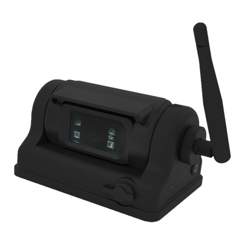
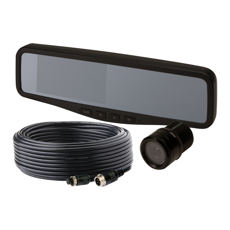
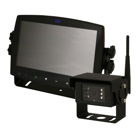
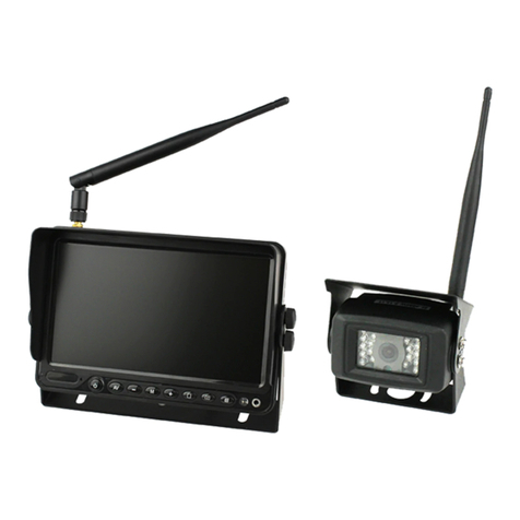
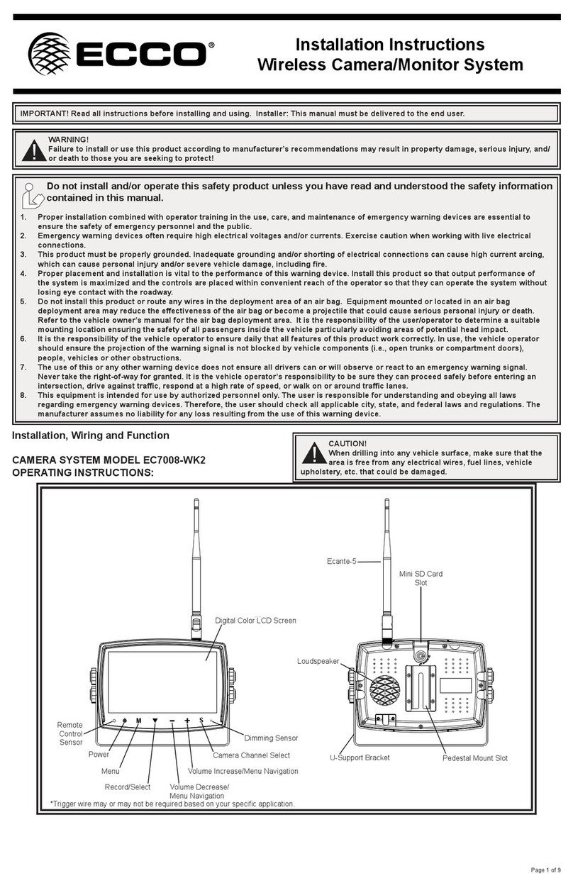
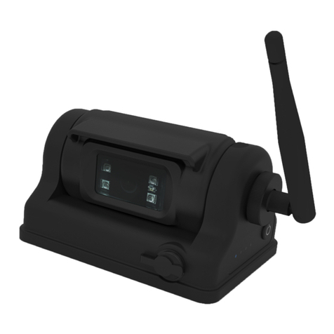
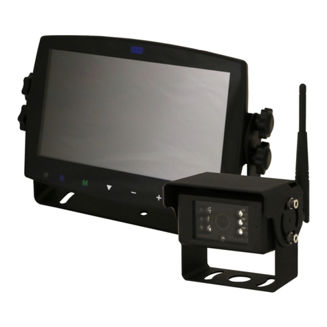
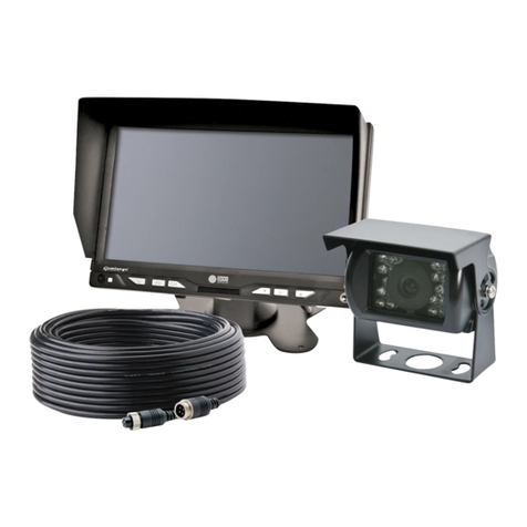
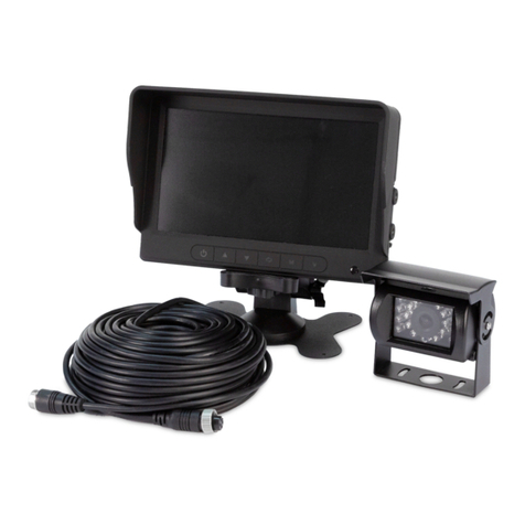
Ecco Gemineye EC2014-C Owner's manual

Page 1 of 10
IMPORTANT! Read all instructions before installing and using. Installer: This manual must be delivered to the end user.
WARNING!
Failure to install or use this product according to manufacturer’s recommendations may result in property damage, serious injury, and/
or death to those you are seeking to protect!
Do not install and/or operate this safety product unless you have read and understood the safety information
contained in this manual.
1. Proper installation combined with operator training in the use, care, and maintenance of emergency warning devices are essential to
ensure the safety of emergency personnel and the public.
2. Emergency warning devices often require high electrical voltages and/or currents. Exercise caution when working with live electrical
connections.
3. This product must be properly grounded. Inadequate grounding and/or shorting of electrical connections can cause high current arcing,
which can cause personal injury and/or severe vehicle damage, including re.
4. Proper placement and installation is vital to the performance of this warning device. Install this product so that output performance of
the system is maximized and the controls are placed within convenient reach of the operator so that they can operate the system without
losing eye contact with the roadway.
5. Do not install this product or route any wires in the deployment area of an air bag. Equipment mounted or located in an air bag
deployment area may reduce the eectiveness of the air bag or become a projectile that could cause serious personal injury or death.
Refer to the vehicle owner’s manual for the air bag deployment area. It is the responsibility of the user/operator to determine a suitable
mounting location ensuring the safety of all passengers inside the vehicle particularly avoiding areas of potential head impact.
6. It is the responsibility of the vehicle operator to ensure daily that all features of this product work correctly. In use, the vehicle operator
should ensure the projection of the warning signal is not blocked by vehicle components (i.e., open trunks or compartment doors),
people, vehicles or other obstructions.
7. The use of this or any other warning device does not ensure all drivers can or will observe or react to an emergency warning signal.
Never take the right-of-way for granted. It is the vehicle operator’s responsibility to be sure they can proceed safely before entering an
intersection, drive against trac, respond at a high rate of speed, or walk on or around trac lanes.
8. This equipment is intended for use by authorized personnel only. The user is responsible for understanding and obeying all laws
regarding emergency warning devices. Therefore, the user should check all applicable city, state, and federal laws and regulations. The
manufacturer assumes no liability for any loss resulting from the use of this warning device.
Installation and Operation Instructions
Camera/Monitor System

Page 2 of 10
Camera EC2014-C
Image 1/3” CMOS Color
Eective Pixels: 725 x 488
Voltage Requirement 12V
Power Consumption 3 W
Lens F=2.8mm / F=2.0
Lens Angle 120°
Audio Yes
Light Sensor Auto Switch B&W
Infrared LEDs 11 (10M Max. Visibility)
Pigtail Connection: CAM Male 4 Pin Threaded
Housing Aluminum Alloy
Mech. Vibration 10g
Weight 0.74 lbs
Dimensions (WxHxD) 2.87”x2.99”x2.60”
Operating Temp. -22°F to 158°F
IP Rating IP69K
Approvals FCC, CE, C-Tick, E13/R10
Current Draw 0.25A
Monitors EC5603-M 5.6” LCD Monitor EC7003-M 7” LCD Monitor
Image 5.6” LCD Color, 4:3 7” LCD Color, 16:9
Controller Internal/3 Camera Internal/3 Camera
Voltage 12/24VDC 12/24VDC
Power Consumption 5 W 4 W
Mirror Imaging Yes (via Camera and Monitor Switch) Yes (via Camera and Monitor Switch)
Split Screen Feature No No
AV Compatible No No
DVR Compatible No No
Audio Yes Yes
Contrast/Brightness Yes Yes
Light Sensor Day/Night Auto Dim Day/Night Auto Dim
Camera Selection Trigger Wires and Monitor Trigger Wires and Monitor
Connection: CAM Female 4 Pin Threaded Female 4 Pin Threaded
Connection (Monitor Pigtail) Male 13 Pin Male 13 Pin
Connection: CB N/A N/A
Housing Plastic Plastic
Mounting Permanent - HD (2 bracket options
provided)
Permanent - HD (2 bracket options
provided)
Mech. Vibration Pedestal Bracket - 3g
Cradle Bracket - 8g
Pedestal Bracket - 3g
Cradle Bracket - 8g
Weight 2.67 lbs 3.34 lbs
Dimensions (WxHxD) 6.32”x4.52”x1.07” 7.28”x5.07”x1.06”
Operating Temp -4°F to 158°F -4°F to 158°F
Remote Control Yes Yes
Current Draw 0.4A 0.3A
Approvals FCC, CE, C-Tick, E13/R10 FCC, CE, C-Tick, E13/R10
Specications

Page 3 of 10
1. Find an appropriate location for installation.
2. Drill holes according to the size of U-bracket and x the U-bracket.
3. Drill a 3/4” (19mm) hole next to U-bracket.
4. Install the camera and sun-visor on U-bracket.
5. Connect the camera tail with the extension cable from inside the vehicle.
6. Loosen the hex head screws and adjust the camera’s position to get the best view angle in the monitor.
Camera Model EC2014-C
CAUTION!
When drilling into any vehicle surface, make sure that the area is free from any electrical wires, fuel lines, vehicle upholstery, etc. that
could be damaged.
Installation, Wiring and Function
Notes:
1. Larger wires and tight connections will provide longer service life for components. For high current wires it is highly recommended
that terminal blocks or soldered connections be used with shrink tubing to protect the connections. Do not use insulation displacement
connectors (e.g., 3M Scotchlock type connectors).
2. Route wiring using grommets and sealant when passing through compartment walls. Minimize the number of splices to reduce voltage
drop. All wiring should conform to the minimum wire size and other recommendations of the manufacturer and be protected from moving
parts and hot surfaces. Looms, grommets, cable ties, and similar installation hardware should be used to anchor and protect all wiring.
3. Fuses or circuit breakers should be located as close to the power takeo points as possible and properly sized to protect the wiring and
devices.
4. Particular attention should be paid to the location and method of making electrical connections and splices to protect these points from
corrosion and loss of conductivity.
5. Ground termination should only be made to substantial chassis components, preferably directly to the vehicle battery.
6. Circuit breakers are very sensitive to high temperatures and will “false trip” when mounted in hot environments or operated close to their
capacity.
Installation
Important! Mount the camera at a location that provides the best view of the area immediately behind the vehicle. Generally, mounting
locations toward the top of the vehicle provide the best eld of view. Lower mounting locations reduce the eld of view and increase the
likelihood of damage from road spray.
Figure 1

Page 4 of 10
2A INLINE FUSE SUPPLIED
13 PIN FEMALE
13 PIN MALE
Red (Power) +
Black (Ground) -
White Trig. Wire CAM 1 +
Blue Trig. Wire CAM 2 +
Brown Trig. Wire CAM 3+
CAM 1
CAM 2
CAM 3
WIRING DEFINED
Important! Waterproof all connections whether inside or outside the vehicle by using sealant and wrapping with insulation tape. Wrap tape
tightly, overlapping by one-half widths so there are no gaps.
Wiring
Figure 2

Page 5 of 10
Models EC5603-M and EC7003-M
Installation instruction of using U-support bracket
1. Select suitable position on vehicle and x the U-support bracket with screws (Figure 3)
2. Fix the monitor to the U-support bracket with angle adjustment screws and adjust the view angle of the monitor
3. Put on the sun-visor and connect the monitor with the AV and power supply conversion cable (Figure 4)
Figure 4
Installation: EC5603-M/EC7003-M
Monitors
WARNING!
To prevent accidental shock, DO NOT OPEN THE MONITOR CASE. Opening the monitor case will expose the inside of the monitor to
conditions that could adversely aect performance. Any evidence of tampering with sealed components will void the warranty.
Important! Do not expose the monitor to water, it is not waterproof. Any water that leaks into the monitor could cause extensive damage.
Figure 3

Page 6 of 10
Installation instruction of using pedestal base
1. Select suitable position on vehicle and x the base support. (Figure 5)
2. Fix the monitor to the base support and adjust the view angle.
3. Put on the sun-visor and connect the monitor with the AV and power supply conversion cable. (Figure 4)
Figure 5
Stick the base
support onto the
vehicle

Page 7 of 10
Power Switch
Vertical Flip
More Brightness
Menu
CALL
SEL
SYS
Horizontal Flip
Setting Selection Up /
Camera Input Selection
Less Brightness
Setting Selection Down /
Camera Input Selection
LANGUAGE
MUTE
MODE
TIMER
Important!
1. Please align the remote control with the infrared-receiving window on the monitor to operate.
2. Never disassemble the remote control or allow it to drop, or become wet.
3. Press the control buttons rmly. Allow 2 seconds for the picture to change
MUTE:
Press to select ENABLE/MUTE sound.
POWER (Power Switch):
Press to turn on/o the monitor.
(Horizontal Turning of Picture):
Press to turn the picture horizontally.
(Vertical Turning of Picture):
Press to turn the picture vertically.
CH (Channel Selection + / Camera Input Selection):
Press to select the upper setting.
CH
(Channel Selection - / Camera Input Selection):
Press to select the lower setting or display the scale.
(Brightness -):
Press to decrease brightness.
(Brightness +):
Press to increase brightness.
MENU MENU:
Press to show menu.
MODE MODE:
Inactive Feature.
CALL CALL:
Scale ON/OFF (Display Mode).
TIMER TIMER:
Inactive Feature.
LANG LANG (Language Selection):
Press to select language display of English, Deutsch,
Français, Español, Português, Italiano, Nederlands, or
Pyccκий options.
SYS SYS:
Press to change resolution.
SEL SEL:
Press to select CAM channels.
Remote Control Operation

Page 8 of 10
Monitor Parts Iden�fica�on
EC5603-M
EC7003-M
Color LCD
Screen
Remote Signal IR Receiver
Power
Menu
Menu Selec�on and Display Mode
Speaker
Installa�on port for
center mount bracket
Camera Select
Light Level
Sensor
Brightness Decrease
Menu selection and display mode
Brightness Increase

Page 9 of 10
Menu Operaons
Press the Menu buon on the remote control or the Menu buon on the monitor screen.
Press the Menu buon several mes to go from one menu to another. Use the channel up/down on the remote control
or the down buon on the monitor screen highlight a menu.
To select the highlighted menu, either use the right brightness color on the remote control or the + buon on the
monitor screen. Press the less brightness buon on the remote control or the – buon on the monitor screen to go
back to the previous menu.
Main Menu
Menu
Opons
Press Menu 1 time
Picture
Bright
Adjust brightness
Contrast
Adjust contrast
Color
Adjust color
Volume
Adjust volume
Auto Dim
On/Off
Scale Adjust
On/Off
Press Menu 2 times
Opon
Language
English
Deutsch
Fran
Espańol
Portuguẻs
Italiano
Nederlands
Pyccкий
Scale
On/Off
Cam 1
Normal/Mirror
Cam 2
Normal/Mirror
Cam 3
Normal/Mirror
Press Menu 3 times
Systems
Color Sys
Auto/PAL/NTSC
Blue Back
On/Off
Horizontal
Vercal
Zoom
16:9/4:3
Press Menu 4 times
Auto Scan
Auto Scan
On/Off
Scan Time
1-90 seconds
Cam 1
On/Off
Cam 2
On/Off
Cam 3
On/Off
Press Menu 5 times
ExitMenu
Main Menu Menu Options
Press Menu 1 time Picture Brightness Adjust brightness
Contrast Adjust contrast
Color Adjust color
Volume Adjust volume
Reset Reset all menu settings using left or right arrow
Software Version View Software Version
Press Menu 2 times Option Cam 1 Normal/Mirror
Cam 2 Normal/Mirror
Cam 3 Normal/Mirror
Press Menu 3 times Systems Language English
Deutsch
Français
Español
Portuguẻs
Italiano
Nederlands
Pyccкий
Resolution Auto
NTSC
PAL
720P25
720P30
1080P25
1080P30
Background Blue/Black
Rear-Trigger-Scale On/O
Auto-dim On/O
Day Adjust brightness
Night Adjust brightness
Press Menu 4 times Auto Scan Auto Scan On/O
Scan Time 1-100 seconds
Cam1 On/O
Cam 2 On/O
Cam 3 On/O
Press Menu 5 times Scale Cam 1 On/O
Cam 2 On/O
Cam 3 On/O
Cam 1-Scale ↑↓ ← →
Cam 2-Scale ↑↓ ← →
Cam 3-Scale ↑↓ ← →
Press menu 6 times Exit Menu

Page 10 of 10
Manufacturer Limited Warranty and Limitation of Liability:
Manufacturer warrants that on the date of purchase, this product will conform to Manufacturer’s specications for this product
(which are available from the Manufacturer upon request). This Limited Warranty extends for twelve (12 ) months from the date
of purchase.
DAMAGE TO PARTS OR PRODUCTS RESULTING FROM TAMPERING, ACCIDENT, ABUSE, MISUSE, NEGLIGENCE,
UNAPPROVED MODIFICATIONS, FIRE OR OTHER HAZARD; IMPROPER INSTALLATION OR OPERATION; OR NOT
BEING MAINTAINED IN ACCORDANCE WITH THE MAINTENANCE PROCEDURES SET FORTH IN MANUFACTURER’S
INSTALLATION AND OPERATING INSTRUCTIONS VOIDS THIS LIMITED WARRANTY.
Exclusion of Other Warranties:
MANUFACTURER MAKES NO OTHER WARRANTIES, EXPRESSED OR IMPLIED. THE IMPLIED WARRANTIES FOR
MERCHANTABILITY, QUALITY OR FITNESS FOR A PARTICULAR PURPOSE, OR ARISING FROM A COURSE OF
DEALING, USAGE OR TRADE PRACTICE ARE HEREBY EXCLUDED AND SHALL NOT APPLY TO THE PRODUCT AND
ARE HEREBY DISCLAIMED, EXCEPT TO THE EXTENT PROHIBITED BY APPLICABLE LAW. ORAL STATEMENTS OR
REPRESENTATIONS ABOUT THE PRODUCT DO NOT CONSTITUTE WARRANTIES.
Remedies and Limitation of Liability:
MANUFACTURER’S SOLE LIABILITY AND BUYER’S EXCLUSIVE REMEDY IN CONTRACT, TORT (INCLUDING
NEGLIGENCE), OR UNDER ANY OTHER THEORY AGAINST MANUFACTURER REGARDING THE PRODUCT AND
ITS USE SHALL BE, AT MANUFACTURER’S DISCRETION, THE REPLACEMENT OR REPAIR OF THE PRODUCT,
OR THE REFUND OF THE PURCHASE PRICE PAID BY BUYER FOR NON-CONFORMING PRODUCT. IN NO EVENT
SHALL MANUFACTURER’S LIABILITY ARISING OUT OF THIS LIMITED WARRANTY OR ANY OTHER CLAIM RELATED
TO THE MANUFACTURER’S PRODUCTS EXCEED THE AMOUNT PAID FOR THE PRODUCT BY BUYER AT THE
TIME OF THE ORIGINAL PURCHASE. IN NO EVENT SHALL MANUFACTURER BE LIABLE FOR LOST PROFITS, THE
COST OF SUBSTITUTE EQUIPMENT OR LABOR, PROPERTY DAMAGE, OR OTHER SPECIAL, CONSEQUENTIAL,
OR INCIDENTAL DAMAGES BASED UPON ANY CLAIM FOR BREACH OF CONTRACT, IMPROPER INSTALLATION,
NEGLIGENCE, OR OTHER CLAIM, EVEN IF MANUFACTURER OR A MANUFACTURER’S REPRESENTATIVE HAS BEEN
ADVISED OF THE POSSIBILITY OF SUCH DAMAGES. MANUFACTURER SHALL HAVE NO FURTHER OBLIGATION OR
LIABILITY WITH RESPECT TO THE PRODUCT OR ITS SALE, OPERATION AND USE, AND MANUFACTURER NEITHER
ASSUMES NOR AUTHORIZES THE ASSUMPTION OF ANY OTHER OBLIGATION OR LIABILITY IN CONNECTION WITH
SUCH PRODUCT.
This Limited Warranty denes specic legal rights. You may have other legal rights which vary from jurisdiction to jurisdiction.
Some jurisdictions do not allow the exclusion or limitation of incidental or consequential damages.
An ECCO SAFETY GROUP™ Brand
ECCOSAFETYGROUP.com
833 West Diamond St, Boise, Idaho 83705
Customer Service USA 800-635-5900
UK +44 (0)113 237 5340 | AUS +61 (0)3 63322444
ECCOESG.com
© 2012 ECCO, Inc. All rights reserved.
920-5202-00 Rev. M
Página 1 de 11
Instrucciones de instalación y operación
Sistema de cámara/monitor
¡ADVERTENCIA!
Si no sigue las instrucciones del fabricante a la hora de instalar o usar el producto, pueden producirse daños materiales, y lesiones
graves o incluso mortales a aquellos que pretende proteger!
No instale ni opere este producto de seguridad, a menos que haya leído y comprendido la información de
seguridad contenida en este manual.
1. Para garantizar su propia seguridad y la de las personas a las que intenta proteger, es esencial una instalación correcta, combinada con
la formación de operador en el uso, cuidado y mantenimiento de los dispositivos de alerta de emergencia.
2. Tenga cuidado cuando manipule conexiones eléctricas con corriente.
3. Este producto debe estar conectado a tierra correctamente. Una conexión a tierra incorrecta o unas conexiones eléctricas
cortocircuitadas pueden provocar arcos de corriente alta, lo que puede ocasionar lesiones personales o daños graves en el vehículo,
incluso un incendio.
4. La colocación e instalación adecuadas son vitales para el buen funcionamiento de este dispositivo de alarma. Instale este producto
de forma que permita un rendimiento óptimo del sistema y los controles estén situados de modo que el operador pueda alcanzarlos
cómodamente y manejar el sistema sin perder en ningún momento el contacto visual con la calzada.
5. No instale este producto ni coloque los cables en la zona de despliegue de un airbag. Si el equipo se monta o coloca en la zona de
despliegue de un airbag, el airbag perderá ecacia o el equipo puede salir despedido, lo cual puede causar lesiones graves o incluso
mortales. Consulte el manual del propietario del vehículo para conocer la zona de despliegue de los airbags. El usuario u operador son
responsables de determinar una posición de montaje adecuada que garantice la seguridad de todos los ocupantes del vehículo, y deben
evitar zonas que puedan provocar golpes en la cabeza.
6. Es responsabilidad del operador del vehículo asegurarse de que todas las características de este producto funcionan correctamente
durante su uso. Durante su uso, el operador del vehículo debe asegurarse de que no haya componentes del vehículo (como los maleteros
o puertas del habitáculo abiertos), personas, vehículos u otros obstáculos que bloqueen la señal de alarma.
7. El uso de este o cualquier otro dispositivo de alarma no garantiza que los conductores puedan o quieran observar o reaccionar a la señal
de alarma. Nunca dé por hecho que tiene prioridad de paso. Es responsabilidad enteramente suya asegurarse de que puede continuar
de forma segura antes de entrar en una intersección, conducir en sentido contrario, responder a una gran velocidad o caminar por los
carriles de tráco o cerca de ellos.
8. El uso de este equipo está destinado exclusivamente a personal autorizado. El usuario es responsable de conocer y acatar todas las
leyes vigentes relacionadas con dispositivos de señales de advertencia. Por lo tanto, el usuario debe comprobar todas las leyes y
normativas de ámbito metropolitano, regional, nacional y cualquier otro ámbito pertinente. El fabricante no asume responsabilidad alguna
por pérdidas derivadas del uso de este dispositivo de alarma.
¡IMPORTANTE! Lea todas las instrucciones antes de instalar y utilizar. Instalador: Este manual se debe entregar al usuario nal.

Página 2 de 11
Cámara EC2014-C
Imagen Color de 1/3 pulg. (86 mm) CMOS
Píxeles efectivos: 725 x 488
Requisito de tensión: 12 V
Consumo energético 3 W
Lente F = 2,8 mm/F = 2,0
Ángulo de la lente 120°
Audio Sí
Sensor de luz Interruptor automático a ByN
LED infrarrojos 11 (visibilidad máx. 10 m)
Conexión de cable exible: CAM Macho roscado de 4 clavijas
Alojamiento Aleación de aluminio
Vibración mec. 10 g
Montaje Trasero/delantero
Peso 0,74 lb (0,34 kg)
Dimensions
(Ancho x Alt. x Prof.)
2,87 pulg. (7,29 cm) x 2,99 pulg.
(7,59 cm) x 2,60 pulg. (6,60 cm)
Temp. de funcionamiento -22°F a 158°F
Clasicación de IP IP69K
Aprobaciones FCC, CE, C-Tick, E13/R10
Consumo de corriente 0.25A
Especicaciones

Página 3 de 11
Monitores Monitor LCD EC5603-M de 5,6 pulg. Monitor LCD EC7003-M de 7 pulg.
Imagen Color LCD de 5,6 pulg., 4:3 Color LCD de 7 pulg., 16:9
Controlador Interno/3 cámara Interno/3 cámara
Tensión 12/24 V CC 12/24 V CC
Consumo energético 5 W 4 W
Imagen de espejo Sí (mediante el interruptor de cámara y
monitor)
Sí (mediante el interruptor de cámara y
monitor)
Funcionalidad de pantalla dividida No No
Compatible con AV No No
Compatible con DVR No No
Audio Sí Sí
Contraste/brillo Sí Sí
Sensor de luz Atenuación autom. día/noche Atenuación autom. día/noche
Selección de cámara Cables de activación y Monitor Cables de activación y Monitor
Conexión: CAM Hembra roscada de 4 clavijas Hembra roscada de 4 clavijas
Conexión (cable exible del monitor) Macho de 13 clavijas Macho de 13 clavijas
Conexión: CB N/D N/D
Alojamiento Plástico Plástico
Montaje Permanente - HD (se proveen 2
opciones de soporte)
Permanente - HD (se proveen 2
opciones de soporte)
Vibración mec. Soporte de pedestal - 3 g
Soporte de base - 8 g
Soporte de pedestal - 3 g
Soporte de base - 8 g
Peso 2,67 lb (1,21 kg) 3,34 lb (1,51 kg)
Dimensiones (Ancho x Alt. x Prof.) 6,32 pulg. (16,05 cm) x 4,52 pulg.
(11,48 cm) x 1,07 pulg. (2,72 cm)
7,28 pulg. (18,49 cm) x 5,07 (12,88 cm)
x 1,06 pulg. (2,69 cm)
Temp. de funcionamiento -4°F a 158°F -4°F a 158°F
Control remoto Sí Sí
Consumo de corriente 0.4A 0.3A
Aprobaciones FCC, CE, C-Tick, E13/R10 FCC, CE, C-Tick, E13/R10

Página 4 de 11
1. Busque una ubicación adecuada para la instalación.
2. Perfore oricios de acuerdo con el tamaño del soporte en U y je el soporte en U.
3. Perfore un oricio de 3/4 pulg. (19 mm) a continuación del soporte en U.
4. Instale la cámara y la visera en el soporte en U.
5. Conecte la cola de la cámara con el cable de extensión desde el interior del vehículo.
6. Aoje los tornillos de cabeza hexagonal y ajuste la posición de la cámara para lograr el mejor ángulo de visión en el monitor.
Cámara modelo EC2014-C
¡PRECAUCIÓN!
Al perforar cualquier supercie del vehículo, asegúrese de que no haya cables eléctricos, mangueras de combustible, tapicería, etc. en
el área que pudiesen dañarse.
Instalación, cableado y función
Notas:
1. Los cables más largos y las conexiones bien ajustadas ofrecerán una mayor vida útil a los componentes. Para cables de alta corriente, se
recomienda usar bloques de terminales o conexiones soldadas cuando se intube por contracción para proteger las conexiones. No usa
conectores de por desplazamiento en aislamiento (p. ej., conectores tipo Scotchlock de 3M)
2. Enrute el cableado utilizando pasacables y sellante cuando atraviese las paredes del compartimiento. Minimice el número de empalmes
para reducir la caída de tensión. Las temperaturas ambiente altas (p. ej., debajo de la cajuela) reducirán signicativamente la capacidad
de transmisión de la corriente de cables, fusibles e interruptores. Todo el cableado debe estar en conformidad con el tamaño mínimo de
cable y otras recomendaciones del fabricante, además de estar protegido de las partes móviles y las supercies calientes. Deben usarse
mangueras, pasacables, amarres de cables y accesorios similares de instalación para anclar y proteger todo el cableado.
3. Los fusibles o interruptores deben ubicarse tan cerca de los puntos de toma de potencia como sea posible y deben ajustarse al tamaño
exacto para proteger el cableado y los dispositivos.
4. Se debe prestar atención especial a la ubicación y al método para hacer las conexiones eléctricas y empalmes para proteger estos puntos
de la corrosión y la pérdida de conductividad.
5. La puesta a tierra solo debe hacerse a componentes sustanciales del chasis, de preferencia directamente a la batería del vehículo.
6. Los interruptores son muy sensibles a altas temperaturas y “se desconectarán falsamente” cuando se monten en ambientes calientes o
se operen cerca de su capacidad.
Instalación
¡Importante! Monte la cámara en la ubicación que proporcione la mejor vista del área inmediatamente detrás del vehículo. Por lo general, las
ubicaciones de montaje hacia la parte superior del vehículo brindan el mejor campo de visión. Las ubicaciones de montaje inferiores reducen
el campo de visión y aumentan la probabilidad de daños por rociado del camino.
Figura 1

Página 5 de 11
Cableado
¡Importante! Impermeabilice todas las conexiones dentro y fuera del vehículo con un sellador y cinta aisladora. Aplique la cinta con rmeza,
superponiendo la mitad del ancho para que no haya espacios libres.
FUSIBLE DE 2 A EN LÍNEA PROVISTO
HEMBRA DE 13 CLAVIJAS MACHO
MACHO DE 13
CLAVIJAS
Rojo (alimentación) +
Negro (tierra) -
Disp. blanco CAM 1 +
Disp. azul CAM 2 +
Disp. marrón CAM 3 +
CAM 1
CAM 2
CAM 3
DEFINICIÓN DEL CABLEADO
Figura 2

Página 6 de 11
Modelos EC5603-M y EC7003-M
Instrucción de instalación usando el soporte en U
1. Seleccione una posición adecuada en el vehículo y je el soporte en U con tornillos (Figura 3)
2. Fije el monitor al soporte en U con tornillos de ajuste en ángulo y ajuste el ángulo de visión del monitor
3. Coloque la visera y conecte el monitor con el cable de conversión de AV y de la fuente de alimentación (Figura 4).
Instalación: EC5603-M/EC7003-M
Monitores
¡ADVERTENCIA!
Para evitar una descarga eléctrica accidental, NO ABRA LA CAJA DEL MONITOR. Al abrir la caja del monitor, el interior quedará
expuesto a condiciones que podrían afectar el desempeño en forma adversa. Cualquier evidencia de alteración de los componentes
sellados anulará la garantía.
¡Importante! No exponga el monitor al agua; no es impermeable. Toda el agua que se ltre dentro del monitor podría causar daños
importantes.
Figura 4
Figura 3

Página 7 de 11
Instrucción de instalación usando la base de pedestal
1. Seleccione una posición adecuada en el vehículo je el soporte de la base. (Figura 5)
2. Fije el monitor al soporte de la base y ajuste el ángulo de visión.
3. Coloque la visera y conecte el monitor con el cable de conversión de AV y de la fuente de alimentación (Figura 4).
Figura 5
Adhiera el apoyo
de la base
al vehículo

Página 8 de 11
Interruptor de encendido
Accomodación vertical
Más brillo
Menú
Llamada
Seleccionar CÁM1/CÁM2/
CÁM3
PAL/AUTO/NTSC
Accomodación horizontal
Selección de conguraciones arriba /
O selección de entrada de cámara
Menos brillo
Selección de conguraciones abajo /
O selección de entrada de cámara
Selección de idioma
Silencio
Modalidad de imagen
Temporizador
¡Importante!
1. Alinee el control remoto con la ventana con recepción infrarroja en el monitor para que funcione.
2. No desarme nunca el control remoto ni deje que se caiga o humedezca.
3. Presione rmemente el botón del control. Espere 2 sequndos para que cambie la imagen.
SILENCIO:
Presione seleccionar PERMITIR/SILENCIAR el sonido.
ENCENDIDO (Interruptor de encendido):
Presione para encender/apagara el monitor.
(Rotar de manera horizontal la imagen):
Presione para girar la imagen de manera horizontal.
(Rotar de manera vertical la imagen):
Presione para girar la imagen de manera vertical.
CH (Selección del canal + / O selección de entrada de
cámara):
Presione para seleccionar la conguración superior.
CH
(Selección del canal - / O selección de entrada de
cámara):
Presione para seleccionar la conguración inferior o mostrar la
escala.
: Presione para disminuir el brillo.
: Presione para aumentar el brillo.
MENU MENÚ:
Presione para mostrar el menú.
MODE Modalidad (Modalidad de imagen):
Característica inactiva.
CALL LLAMADA:
Escala de encendido / apagado (modo de visualización).
TIMER TEMPORIZADOR:
Característica inactiva.
LANG IDIOMA (Selección de idiomas):
Presione para selecionar la visualización de opciones de
idomas de inglés, alemán, francés, español, portugués,
italiano, neerlandés, o ruso.
SYS SYS:
Cambiar la resolución.
SEL SEL:
Presione para seleccionar los canales de la cámara.
Funcionamiento del control remoto:

Página 9 de 11
Idenficacion de las piezas:
EC5603-M
EC7003-M
Encendido
disminución de brillo
aumento de brillo
Tecla de salto
Altavoz
Puerto de instalación
para el soporte de
montaje
Pantalla
LCD a
color
Receptor IR del control
remote
Menú
Selección de Menú y Modo de pantalla
LDR
Cámara seleccionada
sensor de Nivel
de Luz
Selección de menú y modo de visualización

Página 10 de 11
Menú Operaciones
Presione el botón de Menú del control remoto o el botón de Menú en la pantalla del monitor.
Presione el botón de Menú varias veces para pasar de un menú al otro. Ulice subir/bajar de canal del control remoto o
el botón hacia abajo en la pantalla del monitor para resaltar un menú.
Para seleccionar el menú resaltado, ulice el botón de brillo derecho del control remoto o el botón + en la pantalla del
monitor. Presione el botón menos brillo del control remoto o el botón - en la pantalla del monitor para volver al menú
anterior.
Menú principal
Menú
Opciones
Presione Menú 1 vez
Imagen
Brillo
Ajustar brillo
Contraste
Ajustar contraste
Color
Ajustar color
Volumen
Ajustar volumen
Atenuación automáca
Enc./Apag.
Ajustar escala
Enc./Apag.
Presione Menú 2 veces
Opción
Idioma
Inglés
Deutsch
Fran
Espańol
Portuguẻs
Italiano
Nederlands
Pyccкий
Escala
Enc./Apag.
Cám 1
Normal/espejo
Cám 2
Normal/espejo
Cám 3
Normal/espejo
Presione Menú 3 veces
Sistemas
Sist. de color
Auto/PAL/NTSC
Fondo azul
Enc./Apag.
Horizontal
Vercal
Zoom
16:9/4:3
Presione Menú 4 veces
Buscador automáco
Buscador automáco
Enc./Apag.
Tiempo de búsqueda
1-90 segundos
Cám 1
Enc./Apag.
Cám 2
Enc./Apag.
Cám 3
Enc./Apag.
Presione Menú 5 veces
Salir del Menú
Menú Principal Menú Opciones
Presione Menú 1 vez Imagen Brillo Ajustar brillo
Contraste Ajustar contraste
Color Ajustar color
Volumen Ajustar volumen
Reiniciar Restablecer todas las conguraciones del menú usando la echa
izquierda o derecha
Versión del software Ver la versión del software
Presione Menú 2 veces Opción Cám 1 Normal/espejo
Cám 2 Normal/espejo
Cám 3 Normal/espejo
Presione Menú 3 veces Sistemas Idioma Inglés
Deutsch
Français
Español
Portuguẻs
Italiano
Nederlands
Pyccкий
Resolución Auto
NTSC
PAL
720P25
720P30
1080P25
1080P30
Antecedentes Azul/Negra
Escala de gatillo trasero Enc./Apag.
Auto/oscuro Enc./Apag.
Dia Ajuste el brillo
Noche Ajuste el brillo
Presione Menú 4 veces Buscador automático Buscador automático Enc./Apag.
Tiempo de búsqueda 1-100 segundos
Cám 1 Enc./Apag.
Cám 2 Enc./Apag.
Cám 3 Enc./Apag.
Presione Menú 5 veces Escala Cám 1 Enc./Apag.
Cám 2 Enc./Apag.
Cám 3 Enc./Apag.
Cám 1 - Escala ↑↓ ← →
Cám 2 - Escala ↑↓ ← →
Cám 3 - Escala ↑↓ ← →
Presione Menú 6 veces Salir del Menú
An ECCO SAFETY GROUP™ Brand
ECCOSAFETYGROUP.com
833 West Diamond St, Boise, Idaho 83705
Servicio Al Cliente EE.UU. 800-635-5900
Reino Unido +44 (0)113 237 5340 | AUS +61 (0)3 63322444
ECCOESG.com
Other manuals for Gemineye EC2014-C
1
This manual suits for next models
2
Table of contents
Languages:
Other Ecco Digital Camera manuals

Ecco
Ecco K7000B User manual

Ecco
Ecco EC7008-WK User manual

Ecco
Ecco EC7008-WK2 User manual

Ecco
Ecco EC2028-WC User manual

Ecco
Ecco C2013B-WC Installation instructions

Ecco
Ecco C2013B User manual

Ecco
Ecco EC2027-WC User manual

Ecco
Ecco EC2015-C User manual

Ecco
Ecco EC2030-WC User manual

Ecco
Ecco K7010-K User manual