Page 6 of 11
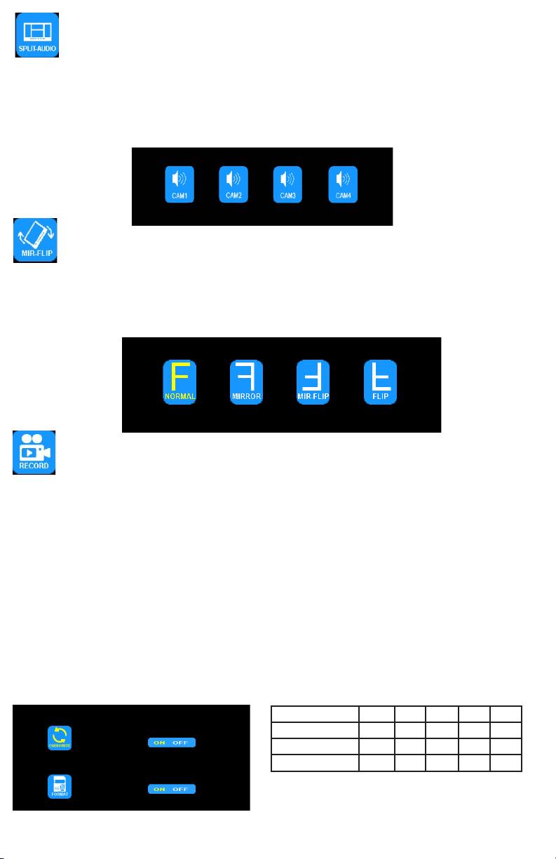
MENU OPTION: SPLIT-AUDIO
ON/OFF SELECTION
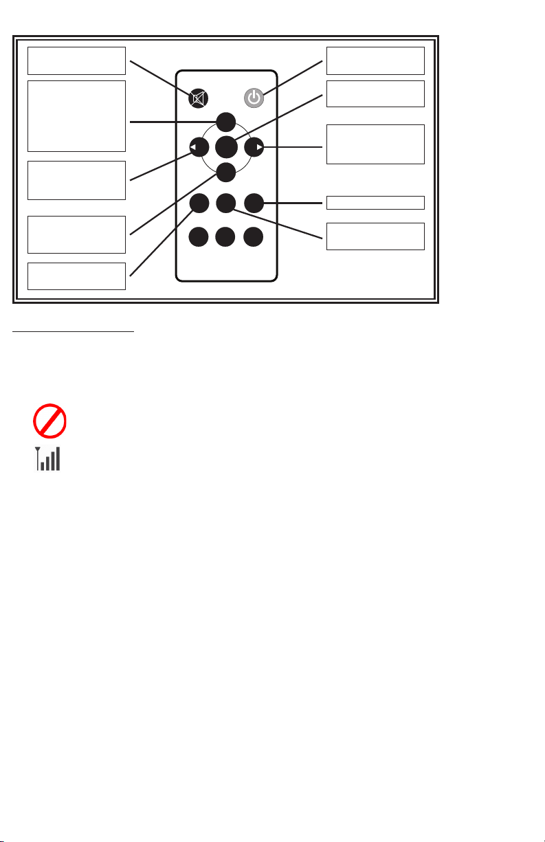
Using the monitor:
1. Press M to enter the Menu
2. Use the + or - to highlight the SPLIT-AUDIO option
3. Press the down arrow to enter the SPLIT-AUDIO menu
4. Use the + or - to highlight/select the camera to deliver audio
5. Press M twice to return to the main screen
Using the remote:
1. Press MENU to enter the Menu
2. Use the < or > to highlight the SPLIT-AUDIO option
3. Press OK to enter the SPLIT-AUDIO menu
4. Use the < or > to highlight/select the camera to deliver audio
5. Press MENU twice to return to the main screen
Audio from one camera is selected through the split audio menu option. Return to any single image mode to adjust the volume. The volume selected during any single
camera image mode will carry over to all other image modes. Volume can not be adjusted during split or quad image modes.
MENU OPTION: MIR-FLIP
ROTATION/FLIP OPTIONS
Using the monitor:
1. Press S to enter the single image mode to be adjusted.
2. Press M to enter the Menu
3. Use the + or - to highlight the MIR-FLIP Option
4. Press the down arrow to enter the MIR-FLIP Option
5. Use the + or - to highlight the desired orientation
6. Press M twice to return to the main screen
Using the remote:
1. Press SEL to enter the single image mode to be adjusted
2. Press MIR to rotate the image
Mode 8G 16G 32G 64G 128G
SINGLE (640x480x1) 14h 28h 55h 110h 220h
QUAD (320x240x4) 11h 22h 43h 86h 172h
SPLIT (400x480x2) 13h 25h 50h 101h 201h
MENU OPTION: RECORD
RECORDING OPTIONS
Using the monitor:
1. Press M to enter the Menu
2. Use the + or - to highlight the RECORD Option
3. Press the down arrow to enter the RECORD Option
4. Use the + or - to highlight the desired adjustment
5. Press M twice to return to the main screen
Using the remote:
1. Press MENU to enter the Menu
2. Use the < or > to highlight the RECORD Option
3. Press OK to enter the RECORD Option
4. Use the < or > to highlight the desired adjustment
5. Press MENU twice to return to the main screen
Enable/Disable Recording
A blue rectangle at the top of the monitor will indicate active recording as long as a mini SD card has been been installed and
formatted. See further sections for details. To enable or disable recording in split or quad view, press the down arrow on the
monitor or the OK on the remote.
Once OVERWRITE is enabled, any recording that takes place after the mini SD card is to capacity, the system will automatically start overwriting existing recordings.
See the table below for recording capacities.
To enable overwrite or to format a mini SG card
The record function is passcode protected. At initial startup, a 4 digit numerical passcode can be established in order to access the menu. Press the
down arrow to select rst digit, when number is red, use + or - to select 0 through 9. Press the down arrow to move to the next number and continued until
desired 4 digit pin is nished. Press the down arrow to conrm. This passcode will also be used for accessing the playback menu and will be the same 4
digits. In order to access the menu again, you will be prompted to enter the passcode again.
Once the pass code has been set, you can set automatic recording upon start up by selecting the record menu by pressing the down arrow. Use the + or -
to select ON or OFF. Press the down arrow to exit and press M to exit the menu.