Page 2 of 4
Pattern Select Operation:
Notes on Synchronizing and Phase (Sync Ph):
Notes on Choosing Flash Patterns:
Notes on Dim Control:
The light head intensity may be reduced if necessary. The Blue wire when con-
nected to positive will reduce the intensity to 25% for SAE patterns. Light intensity
for ECE patterns will reduce to 55%.
NOTE: The blue wire must be disconnected from any voltage when not activating
DIM nor changing ash patterns.
The light head ash pattern may be changed by touching the Blue wire to ground for the following intervals (while the light head is ashing):
NOTE: The blue wire must be disconnected from any voltage when not activating DIM nor changing ash patterns.
- When the light head signal becomes steady, disconnect the Blue wire and the ash pattern will increment by one pattern.
- When the light head signal becomes steady, then goes o, disconnect the Blue wire and the ash pattern will decrement by one pattern.
- When the light head signal becomes steady, then goes o, then becomes steady again, disconnect the Blue wire and the ash pattern will reset to the factory default
pattern.
- When the light head signal becomes steady, then goes o, then becomes steady again, then goes o again, disconnect the Blue wire and the ash pattern will become
set to the steady burn mode.
Wiring Instructions:
RED: Positive, (5A fuse required)
WHITE: Positive, (5A fuse required)
BLACK: Negative
BLUE: Pattern select to negative -- Dim control to positive
YELLOW: Synchronized Function (Up to 32 units can be Synchronized)
Caution! When drilling into any vehicle surface,
make sure that the area is free from any electrical wires,
fuel lines, vehicle upholstery, etc. that could be damaged.
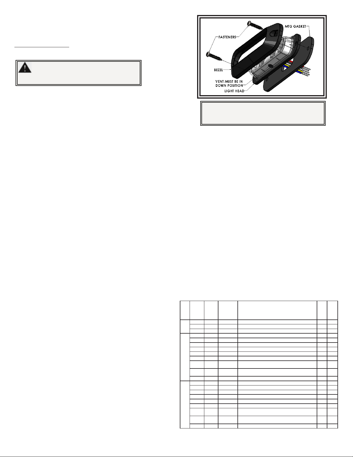
Installation and Mounting:
Important! This unit is a safety device, and it must be
connected to its own separate, fused power point to as-
sure its continued operation should any other electrical
accessory fail.
To mount the light head, use the bezel as a template to mark the mounting holes. The
supplied self-tapping #6 x 0.75” screws typically use 0.125” diameter holes but this may vary
depending on the type of material and the thickness being tapped. Provide a minimum 0.50”
diameter hole for the wires. Grommet the hole if possible and seal with RTV sealant.
It is important to note:
The light head has a small round hole covered with vent membrane that must face
downward when mounting the light head.
A variety of ash patterns may be chosen for the light head. The Multi Color light heads are split vertically as separate lighted areas that may be chosen to operate alter-
nately. The areas are denoted by: Primary color 1&3 (color1 on the left side and color3 on the right, typically the same color) and Secondary color 2&4 (color2 on the left
side and color4 on the right, typically the same color). This allows for patterns that ash right-left using various multiple color combinations.
A separate ash pattern may be assigned for the power wires red, white, or both connected together and the pattern operated depending which wire or wires are ener-
gized. Power the red or the white wires (or both together) then use the pattern select blue wire (touch to ground) to select the chosen ash pattern from the list below.
See the legend at the top of the pattern list for compliance with various standards.
(Up to 32 light heads can be Synchronized by connecting their yellow wires).
When the yellow wires of the light heads are connected together, the group with
Ph1 ash patterns will ash simultaneously. If the light heads in the second group
are set to Ph2 ash patterns, they will ash alternately with the rst group. To
simplify the set-up of a synchronized installation, the following process is recom-
mended:
1. Before connecting the yellow wires together, choose the desired ash pattern
for each light head. The patterns chosen must have the same ash
rate for all light heads intended to be synchronized. (By denition
a 75fpm light head will not sync with at 120fpm light head) To avoid
confusion set each light head individually to the chosen ash pattern using
the blue pattern select wire. Ph1 light heads will alternate with Ph2 light
heads and simultaneously with all other light heads set to Ph1. Ph2 light
heads ash simultaneously with all other light heads set to Ph2. It is also
strongly recommended that the same style of ash pattern be used on all
heads to produce the most eective warning pattern.
2. Connect the yellow synchronization wires together and check that the light
heads are ashing in a synchronized manner as expected. If a pattern
for one light head appears to be wrong, keep the yellow wire connected
and use the blue pattern select wire to cycle forward or backward for
that individual light head until the correct pattern is selected. Once that is
completed verify the light head is synchoronized correctly.
PATTERN
GROUP
RED
WIRE
LED
Color
1&3
WHITE
WIRE
LED
Color
2&4
RED &
WHITE
WIRE LED
Color 1&3,
Color 2&4
FLASH PATTERN
SYNC
Complies
with
0
1-Default Cycle Flash Color 1&3 no
1-Default Cycle Flash Color 2&4 no
1-Default Cycle Flash Color 1&3 and Color 2&4 no
1
2 2 Single 75FPM Ph1 Color 1 Sync Color 3 yes SC
3 3 Single 75FPM Ph2 Color 1 Sync Color 3 yes SC
4 Single 75FPM Ph1 Color 1 Alt Color 4 yes
5 Single 75FPM Ph2 Color 1 Alt Color 4 yes
2 6 Single 75FPM Ph1 Color 2 Sync Color 4 yes SC
3 7 Single 75FPM Ph2 Color 2 Sync Color 4 yes SC
4 4 8 Single 75FPM (Color 1 Sync Color 3) Alt (Color 2 Sync Color
4) (Phase 1) yes SC
5 5 9 Single 75FPM (Color 1 Sync Color 3) Alt Color 2 Sync Color
4) (Phase 2) yes SC
6 6 10 Single 75FPM Color 1 Alt Color 2 Alt Color 3 Alt Color 4 yes
2
711 Single 375FPM Ph1 Color 1 Sync Color 3 yes
8 12 Single 375FPM Ph2 Color 1 Sync Color 3 yes
13 Single 375FPM Ph1 Color 1 Alt Color 4 yes
14 Single 375FPM Ph2 Color 1 Alt Color 4 yes
7 15 Single 375FPM Ph1 Color 2 Sync Color 4 yes
8 16 Single 375FPM Ph2 Color 2 Sync Color 4 yes
9 9 17 Single 375FPM (Color 1 Sync Color 3) Alt (Color 2 Sync Color
4) (Phase 1) yes
10 10 18 Single 375FPM (Color 1 Sync Color 3) Alt (Color 2 Sync Color
4) (Phase 2) yes
11 11 19 Single 375FPM Color 1 Alt Color 2 Alt Color 3 Alt Color 4 yes
For patterns that meet SAE J595 Class1 requirements for Red, Blue,
Amber, and White, see Sin chart!
For patterns that meet California Title 13 Class B requirements for
Red, Blue, and Amber, see Cin chart!
For patterns that meet ECE65 Class1 Cat X (night only )require-
ments for Red, Blue, Amber, see E1 in chart!
For patterns that meet ECE65 Class2 Cat X (day & night) require-
ments for Red, Blue, Amber, see E2 in chart!
Flash Patterns ED3744 and ED3755 - Multi Color:
(continued on next page)
MAX 20in lbs.


