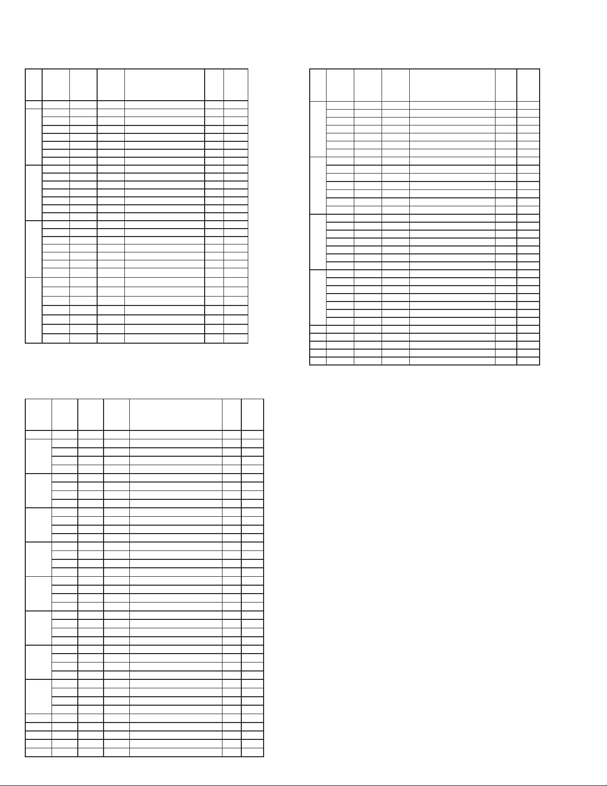
manuals.online logo
Brands
  1. Home
  2. •
  3. Brands
  4. •
  5. Ecco
  6. •
  7. Lighting Equipment
  8. •
  9. Ecco ED3700 Owner's manual

Ecco ED3700 Owner's manual

Page 1 of 4
Installation and Operation Instructions
xxxxxxx
1 Light Head
2 Screws
1 Installation Guide
1 Mounting Gasket
1 Bezel
Light Head Model ED3788 Dual Stack
Input Voltage 12-24VDC
Work Current 1.2 A Max @ 12 VDC Nominal
Physical H x W x L 0.62 in x 2.39 in x 4.72 in
1.58 cm x 6.07 cm x 11.98 cm
Weight 0.24 lb(0.11kg)
Avail Single Colors Red, Blue, Amber, White, Green
Available Dual
Colors
Amb/Wht, Blue/Amb, Blue/Wht, Red/Amb,
Red/Blue, Red/Wht
IMPORTANT! Read all instructions before installing and using. Installer: This manual must be delivered to the end user.
WARNING!
Failure to install or use this product according to manufacturers recommendations may result in property damage, serious injury, and/or
death to those you are seeking to protect!
1. Proper installation combined with operator training in the use, care, and maintenance of emergency warning devices are essential to
ensure the safety of emergency personnel and the public.
2. Emergency warning devices often require high electrical voltages and/or currents. Exercise caution when working with live electrical
connections.
3. This product must be properly grounded. Inadequate grounding and/or shorting of electrical connections can cause high current arcing,
which can cause personal injury and/or severe vehicle damage, including re.
4. Proper placement and installation is vital to the performance of this warning device. Install this product so that output performance of the
system is maximized and the controls are placed within convenient reach of the operator so that s/he can operate the system without losing
eye contact with the roadway.
5. It is the responsibility of the vehicle operator to ensure daily that all features of this product work correctly. In use, the vehicle operator
should ensure the projection of the warning signal is not blocked by vehicle components (i.e., open trunks or compartment doors), people,
vehicles or other obstructions.
6. The use of this or any other warning device does not ensure all drivers can or will observe or react to an emergency warning signal. Never
take the right-of-way for granted. It is your responsibility to be sure you can proceed safely before entering an intersection, drive against
tra󰀩c, respond at a high rate of speed, or walk on or around tra󰀩c lanes.
7. This equipment is intended for use by authorized personnel only. The user is responsible for understanding and obeying all laws regarding
emergency warning devices. Therefore, the user should check all applicable city, state, and federal laws and regulations. The manufacturer
assumes no liability for any loss resulting from the use of this warning device.
Do not install and/or operate this safety product unless you have read and understand the safety information contained in
this manual.
LED SURFACE MOUNT LIGHT HEADS
Dual Stack Single and Split Colors
Contents:
Specications.........................................................................................................01
Installation and Mounting.......................................................................................02
Wiring Instructions.................................................................................................02
Programming Flash Patterns............................................................................02-03
Troubleshooting.....................................................................................................04
Replacement Parts and Accessories.....................................................................04
Warranty.................................................................................................................04
Package Contains:
Operation Environment:
Ambient Temperature: -40 to 65ºC(-40 to 149ºF)
Specications:
Page 2 of 4
A variety of ash patterns may be chosen for the light head. The Dual Stack light heads are split horizontally and vertically providing 4 separate lighted areas in each
light head that may be chosen to ash up-down, right-left, diagonally, and to rotate. The Split Dual Color version also provides di󰀨erent colors for the upper level versus
the lower level.
A separate ash pattern may be assigned for the power wires red, white, or both connected together and the pattern operated depending which wire or wires are ener-
gized. Power the red or the white wires (or both together) then use the pattern select blue wire (touch to ground) to select the chosen ash pattern from one of the lists
below.
Note: The split dual color light heads have a separate ash pattern list.
See the legend at the top of the pattern lists for compliance with various standards.
Pattern Select Operation:
Notes on Synchronizing and Phase (Sync Ph):
Notes on Choosing Flash Patterns:
Notes on Dim Control:
Wiring Instructions:
RED: Positive, (5A fuse required)
WHITE: Positive, (5A fuse required)
BLACK: Negative
BLUE: Pattern select to negative -- Dim control to positive
YELLOW: Synchronized Function (Up to 32 units can be Synchronized)
Important! This unit is a safety device, and it must be
connected to its own separate, fused power point to as-
sure its continued operation should any other electrical
accessory fail.
(Up to 32 light heads can be Synchronized by connecting their yellow wires).
When the yellow wires of the light heads are connected together, the group with Ph1 ash patterns will ash simultaneously. If the light heads in the second group are
set to Ph2 ash patterns, they will ash alternately with the rst group. To simplify the set-up of a synchronized installation, the following process is recommended:
1. Before connecting the yellow wires together, choose the desired ash pattern for each light head. The patterns chosen must have the same ash rate for all light
heads intended to be synchronized. (By denition a 75fpm light head will not sync with at 120fpm light head) To avoid confusion set each light head in-
dividually to the chosen ash pattern using the blue pattern select wire. Ph1 light heads will alternate with Ph2 light heads and simultaneously with all other light
heads set to Ph1. Ph2 light heads ash simultaneously with all other light heads set to Ph2. It is also strongly recommended that the same style of ash pattern
be used on all heads to produce the most e󰀨ective warning pattern.
2. Connect the yellow synchronization wires together and check that the light heads are ashing in a synchronized manner as expected. If a pattern for one light head
appears to be wrong, keep the yellow wire connected and use the blue pattern select wire to cycle forward or backward for that individual light head until the cor-
rect pattern is selected. Once that is completed verify the light head is synchoronized correctly.
The light head intensity may be reduced if necessary. The Blue wire when connected to positive will reduce the intensity to 25% for SAE patterns. NOTE: The blue wire
must be disconnected from any voltage when not activating DIM nor changing ash patterns.
The light head ash pattern may be changed by touching the Blue wire to ground for the following intervals (while the light head is ashing):
NOTE: The blue wire must be disconnected from any voltage when not activating DIM nor changing ash patterns.
- When the light head signal becomes steady, disconnect the Blue wire and the ash pattern will increment by one pattern.
- When the light head signal becomes steady, then goes o󰀨, disconnect the Blue wire and the ash pattern will decrement by one pattern.
- When the light head signal becomes steady, then goes o󰀨, then becomes steady again, disconnect the Blue wire and the ash pattern will reset to the factory default
pattern.
- When the light head signal becomes steady, then goes o󰀨, then becomes steady again, then goes o󰀨 again, disconnect the Blue wire and the ash pattern will become
set to the steady burn mode.
Caution! When drilling into any vehicle surface,
make sure that the area is free from any electrical wires,
fuel lines, vehicle upholstery, etc. that could be damaged.
Installation and Mounting:
To mount the light head, use the bezel as a template to mark the mounting holes. The supplied self-tapping #6 x 0.75”
screws typically use 0.125” diameter holes but this may vary depending on the type of material and the thickness being
tapped. Provide a minimum 0.50” diameter hole for the wires. Grommet the hole if possible and seal with RTV sealant.
It is important to note:
The light head has 2 small round holes covered with vent membrane that must face downward when mounting
the light head.
MAX 20in lbs
Page 3 of 4
PATTERN
GROUP
RED
WIRE
WHITE
WIRE
RED &
WHITE
WIRE
FLASH PATTERN
SYNC
Complies
with
0 1-Default 1-Default 1-Default Cycle Flash No
1
2 2 2 Single Flash 75FPM Alt Up-Dn Ph1 yes S
3 3 3 Single Flash 75FPM Alt Up-Dn Ph2 yes S
4 4 4 Single Flash 75FPM Rotate CCW no
5 5 5 Single Flash 75FPM Rotate CW no
2
6 6 6 Single Flash 120FPM Alt Up-Dn Ph1 yes S
7 7 7 Single Flash 120FPM Alt Up-Dn Ph2 yes S
8 8 8 Single Flash 120FPM Rotate CCW no
9 9 9 Single Flash 120FPM Rotate CW no
3
10 10 10 Double Flash 75FPM Alt Up-Dn Ph1 yes SE2
11 11 11 Double Flash 75FPM Alt Up-Dn Ph2 yes SE2
12 12 12 Double Flash 75FPM Rotate CCW no
13 13 13 Double Flash 75FPM Rotate CW no
4
14 14 14 Double Flash 120FPM Alt Up-Dn Ph1 yes SE2
15 15 15 Double Flash 120FPM Alt Up-Dn Ph2 yes SE2
16 16 16 Double Flash 120FPM Rotate CCW no
17 17 17 Double Flash 120FPM Rotate CW no
5
18 18 18 Quad Flash 75FPM Alt Up-Dn Ph1 yes S
19 19 19 Quad Flash 75FPM Alt Up-Dn Ph2 yes S
20 20 20 Quad Flash 75FPM Rotate CCW no
21 21 21 Quad Flash 75FPM Rotate CW no
6
22 22 22 Quad Flash 150FPM Alt Up-Dn Ph1 yes S
23 23 23 Quad Flash 150FPM Alt Up-Dn Ph2 yes S
24 24 24 Quad Flash 150FPM Rotate CCW no
25 25 25 Quad Flash 150FPM Rotate CW no
7
26 26 26 Triple Flash 75FPM Alt Up-Dn Ph1 yes S
27 27 27 Triple Flash 75FPM Alt Up-Dn Ph2 yes S
28 28 28 Triple Flash 75FPM Rotate CCW no
29 29 29 Triple Flash 75FPM Rotate CW no
8
30 30 30 Quint Flash 150FPM Alt Up-Dn Ph1 yes S
31 31 31 Quint Flash 150FPM Alt Up-Dn Ph2 yes S
32 32 32 Quint Flash 150FPM Rotate CCW no
33 33 33 Quint Flash 150FPM Rotate CW no
9 34 34 34 Steady - Single no
10 35 35 35 Modulation no
11 36 36 36 2 Double Flash, 2 Triple Flash Alt. no
12 37 37 37 4 Single Flash, 2 Quad Flash Alt. no
13 38 38 38 Steady Burn no
Flash Patterns ED3788 Split Dual Color:
For patterns that meet SAE J595 Class1 requirements for Red, Blue, Amber, and White, see Sin chart below!
For patterns that meet ECE R65 Class 2 Cat X (day & night) requirements for Red, Blue, Amber see E2 in chart!
PATTERN
GROUP
RED
WIRE
WHITE
WIRE
RED &
WHITE
WIRE
FLASH PATTERN
SYNC
Complies
with
0
1-Default 1-Default 1-Default
Cycle Flash no
1
2 2 2 Single Flash 75FPM Ph1 Sim yes SC
3 3 3 Single Flash 75FPM Ph2 Sim yes SC
4 4 4 Single Flash 75FPM Up-Down Alt yes S
5 5 5 Single Flash 75FPM Right-Left Alt yes S
6 6 6 Single Flash 75FPM Diagonal Alt yes S
7 7 7 Single Flash 75FPM Rotate CCW no
8 8 8 Single Flash 75FPM Rotate CW no
2
9 9 9 Single Flash 120FPM Ph1 Sim yes SC
10 10 10 Single Flash 120FPM Ph2 Sim yes SC
11 11 11 Single Flash 120FPM Up-Down Alt yes S
12 12 12 Single Flash 120FPM Right-Left Alt yes S
13 13 13 Single Flash 120FPM Diagonal Alt yes S
14 14 14 Single Flash 120FPM Rotate CCW yes
15 15 15 Single Flash 120FPM Rotate CW yes
3
16 16 16 Double Flash 75FPM Ph1 Sim yes SC
17 17 17 Double Flash 75FPM Ph2 Sim yes SC
18 18 18 Double Flash 75FPM Up-Down Alt yes S
19 19 19 Double Flash 75FPM Right-Left Alt yes S
20 20 20 Double Flash 75FPM Diagonal Alt yes S
21 21 21 Double Flash 75FPM Rotate CCW no
22 22 22 Double Flash 75FPM Rotate CW no
4
23 23 23 Double Flash 120FPM Ph1 Sim yes SE2
24 24 24 Double Flash 120FPM Ph2 Sim yes SE2
25 25 25 Double Flash 120FPM Up-Down Alt yes S
26 26 26 Double Flash 120FPM Rt-Left Alt yes S
27 27 27 Double Flash 120FPM Diagonal Alt yes S
28 28 28 Double Flash 120FPM Rotate CCW no
29 29 29 Double Flash 120FPM Rotate CW no
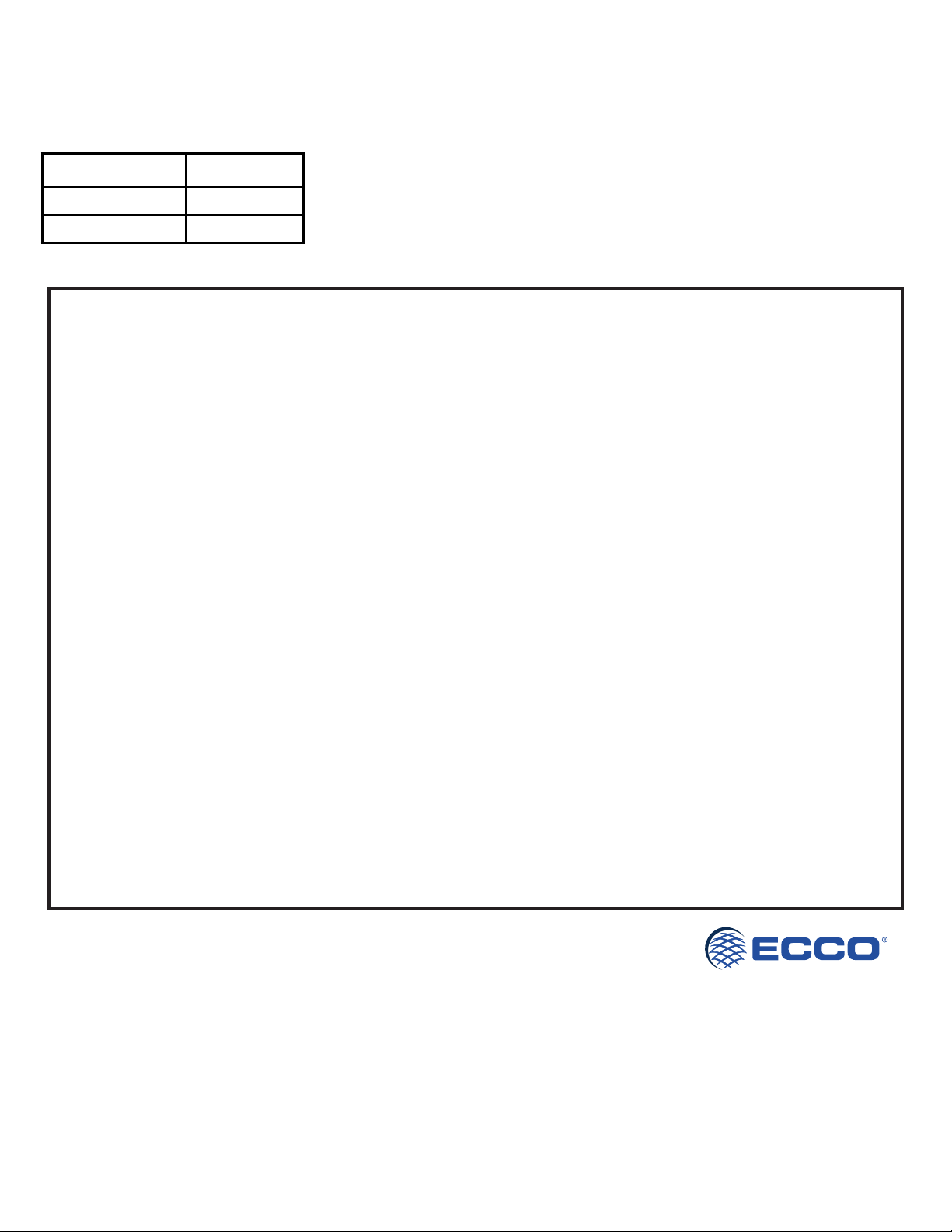
Flash Patterns ED3788 Single Color:
For patterns that meet SAE J595 Class1 requirements for Red, Blue, Amber, and White, see Sin chart below!
For patterns that meet California Title 13 Class B requirements for Red, Blue, and Amber, see Cin chart below!
For patterns that meet ECE R65 Class 2 Cat X (day & night) requirements for Red, Blue, Amber see E2 in chart below!
PATTERN
GROUP
RED
WIRE
WHITE
WIRE
RED &
WHITE
WIRE
FLASH PATTERN
SYNC
Complies
with
5
30 30 30 Quad Flash 75FPM Ph1 Sim yes SC
31 31 31 Quad Flash 75FPM Ph2 Sim yes SC
32 32 32 Quad Flash 75FPM Up-Down Alt yes S
33 33 33 Quad Flash 75FPM Right-Left Alt yes S
34 34 34 Quad Flash 75FPM Diagonal Alt yes S
35 35 35 Quad Flash 75FPM Rotate CCW no
36 36 36 Quad Flash 75FPM Rotate CW no
6
37 37 37 Quad Flash 150FPM Ph1 Sim yes S
38 38 38 Quad Flash 150FPM Ph2 Sim yes S
39 39 39 Quad Flash 150FPM Up-Down Alt yes S
40 40 40 Quad Flash 150FPM Right-Left Alt yes S
41 41 41 Quad Flash 150FPM Diagonal Alt yes S
42 42 42 Quad Flash 150FPM Rotate CCW no
43 43 43 Quad Flash 150FPM Rotate CW no
7
44 44 44 Triple 75FPM Ph1 Sim yes S
45 45 45 Triple 75FPM Ph2 Sim yes S
46 46 46 Triple Flash 75FPM Up-Down Alt yes S
47 47 47 Triple Flash 75FPM Right-Left Alt yes S
48 48 48 Triple Flash 75FPM Diagonal Alt yes S
49 49 49 Triple Flash 75FPM Rotate CCW no
50 50 50 Triple Flash 75FPM Rotate CW no
8
51 51 51 Quint Flash 150FPM Ph1 Sim yes S
52 52 52 Quint Flash 150FPM Ph2 Sim yes S
53 53 53 Quint Flash 150FPM Up-Down Alt yes S
54 54 54 Quint Flash 150FPM Right-Left Alt yes S
55 55 55 Quint Flash 150FPM Diagonal Alt yes S
56 56 56 Quint Flash 150FPM Rotate CCW no
57 57 57 Quint Flash 150FPM Rotate CW no
9 58 58 58 Steady - Single no
10 59 59 59 Modulation no
11 60 60 60 2 Double Flash, 2 Triple Flash Alt. no
12 61 61 61 4 Single Flash, 2 Quad Flash Alt. no
13 62 62 62 Steady Burn no
Page 4 of 4
Replacement Parts and Accessories:
Troubleshooting:
Part/Accs ED3788
Bezel Black Plastic EZD3788BLBZ
Bezel Chrome Plastic EZD3788CHMBZ
The LED Surface Mount series light head has been thoroughly factory tested. If any of the the device functions fail, please check the following:
1. Be sure the power source is activated, then check all connections both positive and ground at the light head (to assure no open or shorted circuits).
2. Permanently connecting the Blue programming wire to ground will disable the light head, no matter what the programmed ash pattern.
3. If the Dim function does not operate, verify the Blue wire is connected to positive.
4. If the sync function is not being used and the light head is functioning erratically, verify the Yellow wire is not connected to positive or ground.
Electronics Controls Company “ECCO” (Manufacturer)
ECCO warrants that on the date of purchase, this product will conform to ECCO’s specications for this product (which are
available from ECCO upon request). This Limited Warranty extends for thirty-six (36) months from the date of purchase.
DAMAGE TO PARTS OR PRODUCTS RESULTING FROM TAMPERING, ACCIDENT, ABUSE, MISUSE, NEGLIGENCE,
UNAPPROVED MODIFICATIONS, FIRE OR OTHER HAZARD; IMPROPER INSTALLATION OR OPERATION; OR NOT
BEING MAINTAINED IN ACCORDANCE WITH THE MAINTENANCE PROCEDURES SET FORTH IN ECCO’S INSTALLA-
TION AND OPERATING INSTRUCTIONS VOIDS THIS LIMITED WARRANTY.
Exclusion of Other Warranties:
ECCO MAKES NO OTHER WARRANTIES, EXPRESSED OR IMPLIED. THE IMPLIED WARRANTIES FOR MERCHANT-
ABILITY, QUALITY OR FITNESS FOR A PARTICULAR PURPOSE, OR ARISING FROM A COURSE OF DEALING,
USAGE OR TRADE PRACTICE ARE HEREBY EXCLUDED AND SHALL NOT APPLY TO THE PRODUCT AND ARE
HEREBY DISCLAIMED, EXCEPT TO THE EXTENT PROHIBITED BY APPLICABLE LAW. ORAL STATEMENTS OR
REPRESENTATIONS ABOUT THE PRODUCT DO NOT CONSTITUTE WARRANTIES.
Remedies and Limitation of Liability:
ECCO’S SOLE LIABILITY AND BUYER’S EXCLUSIVE REMEDY IN CONTRACT, TORT (INCLUDING NEGLIGENCE), OR
UNDER ANY OTHER THEORY AGAINST ECCO REGARDING THE PRODUCT AND ITS USE SHALL BE, AT ECCO’S
DISCRETION, THE REPLACEMENT OR REPAIR OF THE PRODUCT, OR THE REFUND OF THE PURCHASE PRICE
PAID BY BUYER FOR NON-CONFORMING PRODUCT. IN NO EVENT SHALL ECCO’S LIABILITY ARISING OUT OF
THIS LIMITED WARRANTY OR ANY OTHER CLAIM RELATED TO THE ECCO’S PRODUCTS EXCEED THE AMOUNT
PAID FOR THE PRODUCT BY BUYER AT THE TIME OF THE ORIGINAL PURCHASE. IN NO EVENT SHALL ECCO
BE LIABLE FOR LOST PROFITS, THE COST OF SUBSTITUTE EQUIPMENT OR LABOR, PROPERTY DAMAGE, OR
OTHER SPECIAL, CONSEQUENTIAL, OR INCIDENTAL DAMAGES BASED UPON ANY CLAIM FOR BREACH OF CON-
TRACT, IMPROPER INSTALLATION, NEGLIGENCE, OR OTHER CLAIM, EVEN IF ECCO OR A REPRESENTATIVE OF
ECCO HAS BEEN ADVISED OF THE POSSIBILITY OF SUCH DAMAGES. ECCO SHALL HAVE NO FURTHER OBLIGA-
TION OR LIABILITY WITH RESPECT TO THE PRODUCT OR ITS SALE, OPERATION AND USE, AND ECCO NEITHER
ASSUMES NOR AUTHORIZES THE ASSUMPTION OF ANY OTHER OBLIGATION OR LIABILITY IN CONNECTION
WITH SUCH PRODUCT.
This Limited Warranty denes specic legal rights. You may have other legal rights which vary from jurisdiction to jurisdic-
tion. Some jurisdictions do not allow the exclusion or limitation of incidental or consequential damages.
833 West Diamond St
Boise, Idaho 83705
Customer Service
USA 800-635-5900
UK +44 (0)113 237 5340
AUS +61 (0)3 63322444
www.eccoesg.com
© 2019 ECCO Safety Group, Inc. all rights reserved.
920-9915-00 Rev. D

Other Ecco Lighting Equipment manuals

Ecco 5280 Series User manual

Ecco

Ecco 5280 Series User manual

Ecco Axios User manual

Ecco

Ecco Axios User manual

Ecco 27 Series Owner's manual

Ecco

Ecco 27 Series Owner's manual

Ecco 12+ Pro Vantage Series Owner's manual

Ecco

Ecco 12+ Pro Vantage Series Owner's manual

Ecco 6221000 Series User manual

Ecco

Ecco 6221000 Series User manual

Ecco 7950 Owner's manual

Ecco

Ecco 7950 Owner's manual

Ecco ED3788 Owner's manual

Ecco

Ecco ED3788 Owner's manual

Ecco EW4009 Owner's manual

Ecco

Ecco EW4009 Owner's manual

Ecco 10 Series User manual

Ecco

Ecco 10 Series User manual

Ecco Pro Vantage 12+ Series User manual

Ecco

Ecco Pro Vantage 12+ Series User manual

Ecco ULTRAFLEX Series Owner's manual

Ecco

Ecco ULTRAFLEX Series Owner's manual

Ecco ED3744 User manual

Ecco

Ecco ED3744 User manual

Ecco Reflex 5590 Series User manual

Ecco

Ecco Reflex 5590 Series User manual

Ecco ED3704 Owner's manual

Ecco

Ecco ED3704 Owner's manual

Ecco ED3511 Owner's manual

Ecco

Ecco ED3511 Owner's manual

Ecco 3800 Series User manual

Ecco

Ecco 3800 Series User manual

Ecco EB7181 Series User manual

Ecco

Ecco EB7181 Series User manual

Ecco ED3703 Series User manual

Ecco

Ecco ED3703 Series User manual

Ecco DuoBeam User manual

Ecco

Ecco DuoBeam User manual

Ecco EW3108-F Owner's manual

Ecco

Ecco EW3108-F Owner's manual

Ecco Stick-A-LED User manual

Ecco

Ecco Stick-A-LED User manual

Ecco Pro Vantage 12+ Series Installation instructions

Ecco

Ecco Pro Vantage 12+ Series Installation instructions

Ecco EW5430 Series User manual

Ecco

Ecco EW5430 Series User manual

Ecco ED5051VDL Series User manual

Ecco

Ecco ED5051VDL Series User manual

Popular Lighting Equipment manuals by other brands

EuroLite Superstrobe 2700 user manual

EuroLite

EuroLite Superstrobe 2700 user manual

Eastwood 33935 instructions

Eastwood

Eastwood 33935 instructions

GES UC1034-BR2-12LF0-E quick start guide

GES

GES UC1034-BR2-12LF0-E quick start guide

Elation Focus Spot 250R manual

Elation

Elation Focus Spot 250R manual

DTS Scena LED 150 user manual

DTS

DTS Scena LED 150 user manual

Lowel Softcore instructions

Lowel

Lowel Softcore instructions

Sunlight Supply SUN SYSTEM Series Technical information guide

Sunlight Supply

Sunlight Supply SUN SYSTEM Series Technical information guide

MULTIQUIP GLOBUG GB12BW Operation and parts manual

MULTIQUIP

MULTIQUIP GLOBUG GB12BW Operation and parts manual

THORLABS PSY240E installation manual

THORLABS

THORLABS PSY240E installation manual

Panlux LV15HP/CH instructions

Panlux

Panlux LV15HP/CH instructions

GTD LMZ1537 user manual

GTD

GTD LMZ1537 user manual

ProLights EclPanel TWCMini2X1 user manual

ProLights

ProLights EclPanel TWCMini2X1 user manual

Raytec VARIO2 IP 16 Series Full Installation and Setup Guide

Raytec

Raytec VARIO2 IP 16 Series Full Installation and Setup Guide

BELLEDS QLight user guide

BELLEDS

BELLEDS QLight user guide

thomann Stairville Quad Par Profile user manual

thomann

thomann Stairville Quad Par Profile user manual

XAL SONIC Mounting instructions

XAL

XAL SONIC Mounting instructions

Laserworld EL-500RGB KeyTEX manual

Laserworld

Laserworld EL-500RGB KeyTEX manual

Chauvet COLORrail user manual

Chauvet

Chauvet COLORrail user manual

manuals.online logo
manuals.online logoBrands
  • About & Mission
  • Contact us
  • Privacy Policy
  • Terms and Conditions

Copyright 2025 Manuals.Online. All Rights Reserved.