Echelon SPINCO PODIUM User manual


Welcome to our PODIUM family!
From our nationwide SPINCO studios to the comfort of your home, it is our mission to empower and inspire YOU,
our loyal community. We are in the business of revolutionizing lives, one ride at a time. We believe that strength
comes from within, but that we are stronger as one. We are so excited for the opportunity to bring you the Podium:
Canada’s first connected bike, exclusively in collaboration with Echelon. The Podium experience has allowed us to
expand beyond our studio walls, confident that every ride will continue to connect and infuse our community with a
positive, never-quit attitude. We are firm believers that SPINCO is a feeling, not a place. Wherever you are, whenever
you ride, it is our mission to deliver a feeling of intensity, passion, connection, and pride in yourself and your team
across the nation. From the studio to your living room, and any space between, home is where the bike is.
We thank you for your commitment to our community, and for bringing the magic of the SPINCO studio to you. Your
specialized Echelon Fit app grants you exclusive access to professionally filmed classes taught in our SPINCO
studio by instructors from across the country, in addition to access to all Echelon Fit live and on-demand classes
including yoga, stretching and scenic rides. No matter your schedule or fitness level, we are always here for you with
a new and challenging experience. Each Podium is engineered for optimum comfort, smooth functionality, and total
immersion.
You believe it’s your time, you believe it’s your chance. Step up to the Podium and enjoy your ride.
Love,
Michelle August
SPINCO Founder

WORK. SWEAT. ACHIEVE.
PODIUM is engineered for optimum, smooth functionality and total immersion.
Power by Echelon’s award winning guarantee of craftsmanship.
INTRODUCING SPINCO PODIUM
21.5" HD TOUCHSCREEN WITH 180° ROTATION
MULTI-ADJUSTABLE AERO HANDLEBARS
TWO HANDLEBAR MOUNTED BOTTLE HOLDERS
FRONT WHEELS FOR MOBILITY
32 LEVELS OF MAGNETIC RESISTANCE
SPD COMPATIBLE ADJUSTABLE TOE CAGE PEDALS
COMPETITION STYLE SEAT
SEAT SLIDE MOUNTED DUMBBELL HOLDERS
•
•
•
•
•
•
•
•
INTRODURINGSPINCOPODIUM
3

PARTS LIST
4
4
4
3
1
8
7
5
6
9
10 13
11 12
14
16
19
18
15
21
17
2220
24
25
26
2
23
4
INCLUDES
1. Handlebar height
adjustment lever
2. Handlebar post frame
3. Resistance knob/brake lever
4. Crank arms
5. Seat post
6. Seat height adjustment lever
7. Seat slide adjustment knob
8. 21.5" FHD Screen
9. Water bottle holder
10. Handlebars
11. Front foot
12. Rear foot
13. Handlebar post
14. Screen mount
15. Seat
16. Pedals
17. Dumbbell holder
18. Power adapter
19. Double-sided wrench
20. Wrench
21. Small hex key
22. Hex key with Phillips
screwdriver head
23. Handlebar adjustment knob
24. Foot bolts (x4)
25. Water bottle and dumbbell
holder screws (x4)
26. Handlebar post bolt
PARTS LIST
INCLUDES
Handlebar height
adjustment lever
Handlebar post frame
Resistance knob/brake lever
Crank arms
Seat post
Seat height adjustment lever
Seat slide adjustment knob
21.5" FHD Screen
Water bottle holder
Handlebars
Front foot
Rear foot
Handlebar post
Screen mount
Seat
Pedals
Dumbbell holder
Power adapter
Double-sided wrench
Wrench
Small hex key
Hex key with Phillips
screwdriver head
Handlebar adjustment knob
Foot bolts (x4)
Water bottle and dumbbell
holder screws (x4)
Handlebar post bolt
1.
2.
3.
4.
5.
6.
7.
8.
9.
10.
11.
12.
13.
14.
15.
16.
17.
18.
19.
20.
21.
22.
23.
24.
25.
26.

QUICKSTARTGUIDE
5
ACCOUNT CREATION
If this product was purchased on the spincopodium.com website, you will
receive an activation email. Please follow the steps within the email to activate
your account.
6
6
Loosen bolts in order. Remove cardboard and then repeat
on other side.
Remove bolts on both sides with
included tools as shown.
Remove bolts in order.
Remove bolts in order with included
tools as shown.
Hold cardboard piece and remove
frame from bike.
1
1
REMOVAL OF FRAME
2
2
3
1
2
3
6
6
Loosen bolts in order. Remove cardboard and then repeat
on other side.
Remove bolts on both sides with
included tools as shown.
Remove bolts in order.
Remove bolts in order with included
tools as shown.
Hold cardboard piece and remove
frame from bike.
1
1
REMOVAL OF FRAME
2
2
3
1
2
3
6
6
Loosen bolts in order. Remove cardboard and then repeat
on other side.
Remove bolts on both sides with
included tools as shown.
Remove bolts in order.
Remove bolts in order with included
tools as shown.
Hold cardboard piece and remove
frame from bike.
1
1
REMOVAL OF FRAME
2
2
3
1
2
3
6
6
Loosen bolts in order. Remove cardboard and then repeat
on other side.
Remove bolts on both sides with
included tools as shown.
Remove bolts in order.
Remove bolts in order with included
tools as shown.
Hold cardboard piece and remove
frame from bike.
1
1
REMOVAL OF FRAME
2
2
3
1
2
3
6
6
Loosen bolts in order. Remove cardboard and then repeat
on other side.
Remove bolts on both sides with
included tools as shown.
Remove bolts in order.
Remove bolts in order with included
tools as shown.
Hold cardboard piece and remove
frame from bike.
1
1
REMOVAL OF FRAME
2
2
3
1
2
3
6
6
Loosen bolts in order. Remove cardboard and then repeat
on other side.
Remove bolts on both sides with
included tools as shown.
Remove bolts in order.
Remove bolts in order with included
tools as shown.
Hold cardboard piece and remove
frame from bike.
1
1
REMOVAL OF FRAME
2
2
3
1
2
3
1
2
33
2
1
1
2
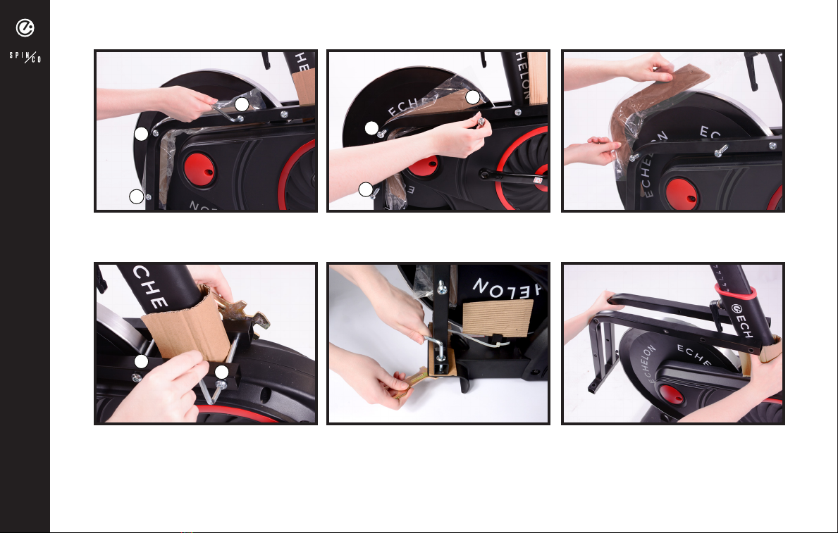
Loosen bolts in order. Remove bolts in order. Remove cardboard and then repeat
on other side.
Hold cardboard piece and remove
frame from bike.
Remove bolts on both sides with
included tools as shown.
Remove bolts in order with included
tools as shown.
REMOVAL OF FRAME
6

7
7
Place the front foot with wheels
facing forward under the
front bracket.
Use a pair of scissors or wire cutters
to cut zip ties around wheel chocks.
Using one of the wrenches, knock
out the front then the back chock.
Use the included hex key to remove
the metal front support bracket.
Tighten down foot bolts with
included hex key.
Insert foot bolts into front foot. Place the rear foot under the
rear bracket.
ASSEMBLY
7
7
Place the front foot with wheels
facing forward under the
front bracket.
Use a pair of scissors or wire cutters
to cut zip ties around wheel chocks.
Using one of the wrenches, knock
out the front then the back chock.
Use the included hex key to remove
the metal front support bracket.
Tighten down foot bolts with
included hex key.
Insert foot bolts into front foot. Place the rear foot under the
rear bracket.
ASSEMBLY
Use a pair of scissors or wire cutters
to cut zip ties around wheel chocks.
Using one of the wrenches, knock
out the front then the back chock.
Use the included hex key to remove
the metal front support bracket.
Place the front foot with wheels
facing forward under the
front bracket.
Place the rear foot under the
rear bracket.
Tighten down foot bolts with
included hex key.
Insert foot bolts into front foot.
ASSEMBLY
7

8
8
Attach dumbbell holder onto seat
post with screws and screwdriver
end of hex key.
Pull the wire out of frame and the wire from base of handlebar post. DO
NOT UNTIE TWIST TIES AT TOP OF HANDLEBAR POST.
Place seat onto seat post and secure
with included wrench.
Insert foot bolts into rear foot. Tighten down foot bolts with
included hex key.
ASSEMBLY
8
8
Attach dumbbell holder onto seat
post with screws and screwdriver
end of hex key.
Pull the wire out of frame and the wire from base of handlebar post. DO
NOT UNTIE TWIST TIES AT TOP OF HANDLEBAR POST.
Place seat onto seat post and secure
with included wrench.
Insert foot bolts into rear foot. Tighten down foot bolts with
included hex key.
ASSEMBLY
Insert foot bolts into rear foot. Tighten down foot bolts with
included hex key.
Attach dumbbell holder onto seat
post with screws and screwdriver
end of hex key.
Pull the wire out of frame and the wire from base of handlebar post.
DO NOT UNTIE TWIST TIES AT TOP OF HANDLEBAR POST.
Place seat onto seat post and secure
with included wrench.
ASSEMBLY
8
9
9
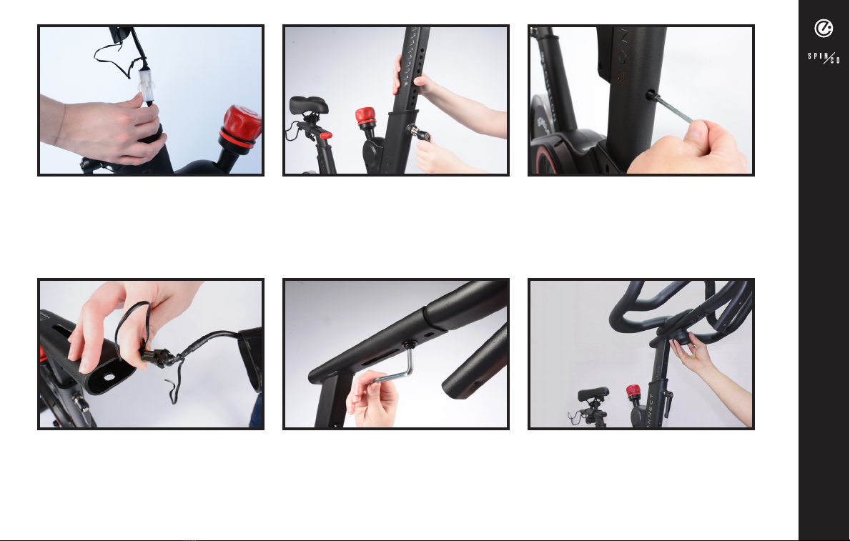
Untie the twist tie at top of
handlebar post, ensuring not to
allow the wire to fall inside of
handlebar post. Connect the wire
from the handlebar post to the wire
at bottom of screen mount.
Place handlebars onto handlebar
post. Secure with handlebar
adjustment knob with adjustment
knob washer.
Connect the one wires from frame
and handlebar post together, then
feed excess wire down into frame.
Insert handlebar post screw into
hole on post. Use small hex key to
tighten. Ensure holes in handlebar
post and handlebar post frame align
properly before inserting handlebar
post bolt.
Unscrew handlebar height
adjustment lever, but do not remove.
Pull lever out and fully insert
handlebar post into frame. Release
lever and post is secure.
Feed excess wire into handlebar
postand slide screen mount into
handlebar post. Secure with tablet
mount post bolts.
ASSEMBLY
9
9
Untie the twist tie at top of
handlebar post, ensuring not to
allow the wire to fall inside of
handlebar post. Connect the wire
from the handlebar post to the wire
at bottom of screen mount.
Place handlebars onto handlebar
post. Secure with handlebar
adjustment knob with adjustment
knob washer.
Connect the one wires from frame
and handlebar post together, then
feed excess wire down into frame.
Insert handlebar post screw into
hole on post. Use small hex key to
tighten. Ensure holes in handlebar
post and handlebar post frame align
properly before inserting handlebar
post bolt.
Unscrew handlebar height
adjustment lever, but do not remove.
Pull lever out and fully insert
handlebar post into frame. Release
lever and post is secure.
Feed excess wire into handlebar
postand slide screen mount into
handlebar post. Secure with tablet
mount post bolts.
ASSEMBLY
Connect the one wires from frame
and handlebar post together, then
feed excess wire down into frame.
Unscrew handlebar height
adjustment lever, but do not remove.
Pull lever out and fully insert
handlebar post into frame. Release
lever and post is secure.
Insert handlebar post screw into
hole on post. Use small hex key to
tighten. Ensure holes in handlebar
post and handlebar post frame align
properly before inserting handlebar
post bolt.
Place handlebars onto handlebar
post. Secure with handlebar
adjustment knob with adjustment
knob washer.
Feed excess wire into handlebar
postand slide screen mount into
handlebar post. Secure with tablet
mount post bolts.
Untie the twist tie at top of
handlebar post, ensuring not to
allow the wire to fall inside of
handlebar post. Connect the wire
from the handlebar post to the wire
at bottom of screen mount.
ASSEMBLY
9
10
10
Slide water bottle holder onto post and secure with two screws.
TROUBLE CONNECTING?
If your bike does not connect using the process above, navigate to the Settings app on
the tablet and select Apps (on older versions of Android you will select ’Application’ and
then ‘Application manger’). At the top right select the icon (on older vversions, select
‘MORE’) and then select ‘Show system’ or ‘Show system apps’. Select ‘Bluetooth Share’,
then ‘Storage’, and then either ‘Clear Data’ or ‘Clear Cache,’ depending which button is
highlighted. Restart the Echelon Fit™ App and attempt connection again. If you have any
issues after completing this process, please contact us at appsupport@echelonfit.com.
ASSEMBLY
10
10
Slide water bottle holder onto post and secure with two screws.
TROUBLE CONNECTING?
If your bike does not connect using the process above, navigate to the Settings app on
the tablet and select Apps (on older versions of Android you will select ’Application’ and
then ‘Application manger’). At the top right select the icon (on older vversions, select
‘MORE’) and then select ‘Show system’ or ‘Show system apps’. Select ‘Bluetooth Share’,
then ‘Storage’, and then either ‘Clear Data’ or ‘Clear Cache,’ depending which button is
highlighted. Restart the Echelon Fit™ App and attempt connection again. If you have any
issues after completing this process, please contact us at appsupport@echelonfit.com.
ASSEMBLY
Slide water bottle holder onto post and secure with two screws.
TROUBLE CONNECTING?
If your bike does not connect using this process, navigate to the Settings app on the tablet and
select Apps (on older versions of Android you will select ’Application’ and then ‘Application
manger’). At the top right select the icon (on older vversions, select ‘MORE’) and then select
‘Show system’ or ‘Show system apps’. Select ‘Bluetooth Share’, then ‘Storage’, and then
either ‘Clear Data’ or ‘Clear Cache,’ depending which button is highlighted. Restart the Echelon
Fit™ App and attempt connection again. If you have any issues after completing this process,
please contact us at [email protected].
ASSEMBLY
10

11
11
TROUBLE CONNECTING?
NOTE: WE RECOMMEND HAVING HELP WITH TABLET INSTALLATION.
ASSEMBLY
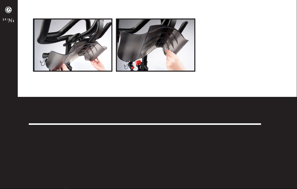
Remove the four preinstalled screws
and set to the side.
Flip mount around to face away
from Connect bike. Hold tablet up
to mount and hand screw all four
screws into tablet. Use screwdriver
end of hex key to tighten.
Unscrew the three small
preinstalled screws from the cover
on the back of the tablet and set
aside. Flip the tablet back over.
Peel the backing off of the included
wire clip.
Place wire clip, as shown above, and
press and hold wire clip down for
ten seconds for proper adhesion.
Plug in power cord to DC input and
place excess cord in wire clip.
11
11
TROUBLE CONNECTING?
NOTE: WE RECOMMEND HAVING HELP WITH TABLET INSTALLATION.
ASSEMBLY
Remove the four preinstalled screws
and set to the side.
Flip mount around to face away
from Connect bike. Hold tablet up
to mount and hand screw all four
screws into tablet. Use screwdriver
end of hex key to tighten.
Unscrew the three small
preinstalled screws from the cover
on the back of the tablet and set
aside. Flip the tablet back over.
Peel the backing off of the included
wire clip.
Place wire clip, as shown above, and
press and hold wire clip down for
ten seconds for proper adhesion.
Plug in power cord to DC input and
place excess cord in wire clip.
Remove the four preinstalled screws
and set to the side.
Flip mount around to face away
from Connect bike. Hold tablet up
to mount and hand screw all four
screws into tablet. Use screwdriver
end of hex key to tighten.
Unscrew the three small
preinstalled screws from the cover
on the back of the tablet and set
aside. Flip the tablet back over.
Plug in power cord to DC input and
place excess cord in wire clip.
Place wire clip, as shown above, and
press and hold wire clip down for
ten seconds for proper adhesion.
Peel the backing off of the included
wire clip.
ASSEMBLY
11

12
12
ASSEMBLY
Pull zip-tie to tighten and secure
cord in place.
Cut excess length off of zip-tie.
Replace the three screws to secure
the cover back on the tablet.
With the power cord still in the
notch, replace cover.
Place power cord in the notch of
the middle perforated section of the
cover and hold in place.
Feed included zip-tie through wire
clip and behind cord, as shown
above.
12
12
ASSEMBLY
Pull zip-tie to tighten and secure
cord in place.
Cut excess length off of zip-tie.
Replace the three screws to secure
the cover back on the tablet.
With the power cord still in the
notch, replace cover.
Place power cord in the notch of
the middle perforated section of the
cover and hold in place.
Feed included zip-tie through wire
clip and behind cord, as shown
above.
Feed included zip-tie through wire
clip and behind cord, as shown
above.
Pull zip-tie to tighten and secure
cord in place.
Cut excess length off of zip-tie.
Replace the three screws to secure
the cover back on the tablet.
With the power cord still in the
notch, replace cover.
Place power cord in the notch of
the middle perforated section of the
cover and hold in place.
ASSEMBLY
12

13
13
ASSEMBLY
Hold pedal with double sided
wrench and use single sided
wrench to tighten nut clockwise.
Finger tighten nut clockwise back
onto pedal bolt.
Remove nut from right pedal by
turning counterclockwise.
Screw right pedal onto right crank
arm clockwise. Use double sided
wrench to ensure pedal is firmly
seated against crank arm.
Remove nut from left pedal by
turning clockwise.
Screw left pedal onto crank arm
counterclockwise. Use double sided
wrench to ensure pedal is firmly seated
against crank arm.
The threads are reversed on LEFT pedal and nut.
13
13
ASSEMBLY
Hold pedal with double sided
wrench and use single sided
wrench to tighten nut clockwise.
Finger tighten nut clockwise back
onto pedal bolt.
Remove nut from right pedal by
turning counterclockwise.
Screw right pedal onto right crank
arm clockwise. Use double sided
wrench to ensure pedal is firmly
seated against crank arm.
Remove nut from left pedal by
turning clockwise.
Screw left pedal onto crank arm
counterclockwise. Use double sided
wrench to ensure pedal is firmly seated
against crank arm.
The threads are reversed on LEFT pedal and nut.
Remove nut from right pedal by
turning counterclockwise.
Screw right pedal onto right crank
arm clockwise. Use double sided
wrench to ensure pedal is firmly
seated against crank arm.
Finger tighten nut clockwise back
onto pedal bolt.
Screw left pedal onto crank arm
counterclockwise. Use double sided
wrench to ensure pedal is firmly seated
against crank arm.
Remove nut from left pedal by
turning clockwise.
Hold pedal with double sided
wrench and use single sided
wrench to tighten nut clockwise.
The threads are reversed on LEFT pedal and nut.
ASSEMBLY
13

14
14
ASSEMBLY
Plug power adapter into port
located on the rear or front foot
bracket, then plug into wall outlet.
Hold pedal with double sided
wrench and use single sided wrench
to tighten nut counterclockwise.
Finger tighten nut counterclockwise
back onto pedal bolt.
14
14
ASSEMBLY
Plug power adapter into port
located on the rear or front foot
bracket, then plug into wall outlet.
Hold pedal with double sided
wrench and use single sided wrench
to tighten nut counterclockwise.
Finger tighten nut counterclockwise
back onto pedal bolt.
14
14
ASSEMBLY
Plug power adapter into port
located on the rear or front foot
bracket, then plug into wall outlet.
Hold pedal with double sided
wrench and use single sided wrench
to tighten nut counterclockwise.
Finger tighten nut counterclockwise
back onto pedal bolt.
Finger tighten nut counterclockwise
back onto pedal bolt.
Hold pedal with double sided
wrench and use single sided wrench
to tighten nut counterclockwise.
Plug power adapter into port
located on the rear or front foot
bracket, then plug into wall outlet.
ASSEMBLY
14

15
15
Turn handlebar adjustment lever
counterclockwise until you are able
to pull the lever halfway out.
Pull and hold the handlebar
adjustment lever and raise or lower
the handlebars to desired position.
Ensure lever engages one of the
adjustment holes. Turn handlebar
adjustment lever clockwise until
secure.
Turn seat slide adjustment lever
counterclockwise to loosen.
Turn seat height adjustment lever
counterclockwise until you are able
to pull the lever halfway out.
Move seat along track to desired
location. Turn seat slide adjustment
lever clockwise to tighten and
secure in place.
Pull and hold the seat height
adjustment lever and raise the seat
to desired position. Ensure lever
engages one of the adjustment
holes. Turn seat height adjustment
lever clockwise until secure.
SEAT/HANDLEBAR ADJUSTMENT
15
15
Turn handlebar adjustment lever
counterclockwise until you are able
to pull the lever halfway out.
Pull and hold the handlebar
adjustment lever and raise or lower
the handlebars to desired position.
Ensure lever engages one of the
adjustment holes. Turn handlebar
adjustment lever clockwise until
secure.
Turn seat slide adjustment lever
counterclockwise to loosen.
Turn seat height adjustment lever
counterclockwise until you are able
to pull the lever halfway out.
Move seat along track to desired
location. Turn seat slide adjustment
lever clockwise to tighten and
secure in place.
Pull and hold the seat height
adjustment lever and raise the seat
to desired position. Ensure lever
engages one of the adjustment
holes. Turn seat height adjustment
lever clockwise until secure.
SEAT/HANDLEBAR ADJUSTMENT
Turn seat slide adjustment lever
counterclockwise to loosen.
Move seat along track to desired
location. Turn seat slide adjustment
lever clockwise to tighten and
secure in place.
Turn seat height adjustment lever
counterclockwise until you are able
to pull the lever halfway out.
Pull and hold the handlebar
adjustment lever and raise or lower
the handlebars to desired position.
Ensure lever engages one of the
adjustment holes. Turn handlebar
adjustment lever clockwise until
secure.
Turn handlebar adjustment lever
counterclockwise until you are able
to pull the lever halfway out.
Pull and hold the seat height
adjustment lever and raise the seat
to desired position. Ensure lever
engages one of the adjustment
holes. Turn seat height adjustment
lever clockwise until secure.
SEAT/HANDLEBAR ADJUSTMENT
15

SEAT HEIGHT
FITTING THE BIKE TO YOU
Stand beside the bike with your hip next to the saddle and face towards the handlebars. Adjust the saddle up
or down to align the seat with your hip bone height.
Next, hop on into the saddle and clip your shoes into the pedals. To do this, slide your foot forward until you
feel the connection between the bottom of your cleat and the pedal attachment, and then press your foot
straight down into the pedal. To unclip after your ride, simply kick/twist your heel out to the side to release the
clip (see page 15 Shoes & Cleats).
Knees should have a slight bend when fully extended. Hyperextension or too much bend in the knee can cause
injury.
SEAT (FORWARD OR BACK)
Bring your feet to the 3 o’clock and 9 o’clock positions, and have a look at your knee alignment. The knee
should be positioned in line with the pedal axle. The knee should track over the foot but should not extend past
the toe - you should be able to always see your toes past the knee.
HANDLEBAR HEIGHT
Adjust the handlebar height so that the front of the handlebars are slightly higher than seat height. If you have
lower back concerns, the handlebars can be raised additionally to provide additional relief.
FITTINGTHEBIKE TOYOU
16

EVERYTHING YOU NEED TO TAKE THE STUDIO HOME
THE SWEAT UPGRADE
If you purchased The Sweat Upgrade, you will have received a deluxe box of exclusive accessories including
a pair of premium spin shoes, a PODIUM bike mat, a set of custom 3lb dumbbells, and a SPINCO sweat
towel & reusable water bottle.
SHOES & CLEATS
The PODIUM modified cycling shoes can attach to SPD cleats.
In your Sweat Upgrade box, you will find a pair of two-bolt cleats. These are your SPD cleats — the cleats
that connect to your PODIUM.
THESWEATUPGRADE
17

ATTACHING YOUR CLEATS
Put your shoes on and find the ball of your foot. The cycling cleat should be aligned just under the ball
of the foot for maximum comfort, performance and natural movement in the ankles to create a fluid
pedal stroke and help prevent injury.
Determine how your feet are pointed when you attach your cycling shoes to the pedals. Your feet
should feel like they are pointing in their natural direction with no pain or twisting sensation in your hips,
knees or ankles as you pedal. As a good starting point, make sure the cleats are pointed straight on the
shoes and see how that feels.
Make sure the cleats are screwed in as tightly as possible. They should sit nice and snug against the
sole of the shoe and should not shift or rotate while attached.
Clip in and slowly start pedaling. Cycling shoes with cleats are adjustable, but it can be difficult to find
the perfect position on the bike. We recommend clipping in and pedaling slowly so that the cleat
placement allows for the ball of your feet to be at the center of the bike pedal and that your feet direc-
tion feel natural when you are clipped in.
1.
2.
3.
4.
ATTACHINGYOUR CLEATS
18

IT’S A FEELING, NOT A PLACE
THE SPINCO CLASS EXPERIENCE
Whether you are an avid SPINCO rider or new to our community, we firmly believe that everybody is welcome,
and we’re looking forward to riding with you. More than just a ride, and bigger than the bike, our SPINCO
workouts are made to inspire and uplift. It’s about the feeling, not the place. Turn your beats high, set your
lights low, and prepare to journey through our classes as we ride to the beat of the music.
SPINCO offers structured, full-body spin classes designed to strengthen the body, energize the mind and feed
the soul. From the studio to your home, the goal of each SPINCO class is to work together as one team, one
bike. Our team will inspire and empower our community on your journey towards mental and physical health.
Participate in classes on your own time and schedule. Ride your favourite classes on repeat and leverage the
Podium’s advanced connected metrics to compete against yourself.
On top of our exclusive SPINCO class library, your monthly subscription includes thousands of workout
classes to mix things up and exercise your mind and body in new ways. Access scenic rides through the
French countryside, yoga, meditation, stretching, core strength, and a host of additional classes both live, and
on-demand.
No matter the fitness level, prepare to be motivated to achieve higher levels of personal well-being, physical
strength, and positive mental attitude. Get ready to fall into the challenge and find your purpose.
THESPINCOCLASSEXPERIENCE
19

16
16
FEDERAL COMMUNICATIONS COMMISSION (FCC) STATEMENT
15.21
YOU ARE CAUTIONED THAT CHANGES OR MODIFICATIONS NOT EXPRESSLY APPROVED BY THE PART RESPONSIBLE FOR
COMPLIANCE COULD VOID THE USER’S AUTHORITY TO OPERATE THE EQUIPMENT.
15.105(B)
THIS EQUIPMENT HAS BEEN TESTED AND FOUND TO COMPLY WITH THE LIMITS FOR A CLASS B DIGITAL DEVICE,
PURSUANT TO PART 15 OF THE FCC RULES. THESE LIMITS ARE DESIGNED TO PROVIDE REASONABLE PROTECTION AGAINST
HARMFUL INTERFERENCE IN A RESIDENTIAL INSTALLATION. THIS EQUIPMENT GENERATES, USES AND CAN RADIATE
RADIO FREQUENCY ENERGY AND, IF NOT INSTALLED AND USED IN ACCORDANCE WITH THE INSTRUCTIONS, MAY CAUSE
HARMFUL INTERFERENCE TO RADIO COMMUNICATIONS. HOWEVER, THERE IS NO GUARANTEE THAT INTERFERENCE
WILL NOT OCCUR IN A PARTICULAR INSTALLATION. IF THIS EQUIPMENT DOES CAUSE HARMFUL INTERFERENCE TO RADIO
OR TELEVISION RECEPTION, WHICH CAN BE DETERMINED BY TURNING THE EQUIPMENT OFF AND ON, THE USER IS
ENCOURAGED TO TRY TO CORRECT THE INTERFERENCE BY ONE OR MORE OF THE FOLLOWING MEASURES:
-REORIENT OR RELOCATE THE RECEIVING ANTENNA.
-INCREASE THE SEPARATION BETWEEN THE EQUIPMENT AND RECEIVER.
- CONNECT THE EQUIPMENT INTO AN OUTLET ON A CIRCUIT DIFFERENT FROM THAT TO WHICH THE RECEIVER
IS CONNECTED.
- CONSULT THE DEALER OR AN EXPERIENCED RADIO/TV TECHNICIAN FOR HELP.
FCC RF RADIATION EXPOSURE STATEMENT:
1. THIS TRANSMITTER MUST NOT BE CO-LOCATED OR OPERATING IN CONJUNCTION WITH ANY OTHER ANTENNA
OR TRANSMITTER.
2. THIS EQUIPMENT COMPLIES WITH RF RADIATION EXPOSURE LIMITS SET FORTH FOR AN UNCONTROLLED
ENVIRONMENT. THIS EQUIPMENT SHOULD BE INSTALLED AND OPERATED WITH A MINIMUM DISTANCE OF 20 CM
BETWEEN THE RADIATOR AND YOUR BODY.
THIS DEVICE COMPLIES WITH PART 15 OF THE FCC RULES. OPERATION IS SUBJECT TO THE FOLLOWING TWO
CONDITIONS:
1) THIS DEVICE MAY NOT CAUSE HARMFUL INTERFERENCE AND
2) THIS DEVICE MUST ACCEPT ANY INTERFERENCE RECEIVED, INCLUDING INTERFERENCE THAT MAY CAUSE
UNDESIRED OPERATION.
SAFETY INFO AND WARNINGS
SAFETYINFO ANDWARNINGS
20
Table of contents
Other Echelon Exercise Bike manuals


