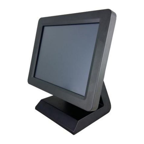
EcLine EC-VP-3100 User manual

EC-VP-3100 User Manual – V1
User Manual
EC-VP-3100
All-in-one Touch POS Terminal

EC-VP-3100 User Manual – V1
CHAPTER
OVERVIEW
1. INFORMATION .................................................................................................... 4
2. ELECTROMAGNETIC COMPATIBILITY STATEMENT .................................................. 5
3. SPECIFICATION ..................................................................................................... 6
4. INSTALLATION GUIDE ........................................................................................... 8
4.1 Appearance ............................................................................................................................... 8
4.2 Power Button ............................................................................................................................. 8
4.3 Rear Panel I/O Connectors ........................................................................................................ 9
5. GETTING START .................................................................................................... 9
5.1 Unpacking .................................................................................................................................. 9
5.2 Optional Parts .......................................................................................................................... 10
5.3 Remove the Rear Cover ........................................................................................................... 10
5.4 Install the Optional Parts ......................................................................................................... 10
5.4.1 Install the MSR ................................................................................................................................ 10
5.4.2 Install the Customer Display. .......................................................................................................... 11
5.4.3 Install the Second Display ............................................................................................................... 11
5.4.4 Connect the Cash Drawer ............................................................................................................... 11
6. INSTALLATION THE DRIVERS AND SOFTWARE ......................................................11
6.1. Install the Touch Screen Driver ............................................................................................... 11
7. IDENTIFY THE PROBLEM ......................................................................................15
7.1 Use the Following Procedure to Troubleshoot Problems ........................................................ 15
7.2 Electricity Failure ..................................................................................................................... 15
7.3 Touch Screen Doesn’t Function ............................................................................................... 15
7.4 Power Failure ........................................................................................................................... 15
7.5 Network / LAN Failure ............................................................................................................. 15
7.6 MSR Failure .............................................................................................................................. 15
7.7 USB Failure .............................................................................................................................. 15
7.8 Cash Drawer Doesn’t Function ................................................................................................ 16
7.9 Re-Boot Continuously .............................................................................................................. 16
7.10 Printer Doesn’t Work ............................................................................................................. 16

EC-VP-3100 User Manual – V1
8. REPLACE FIELD REPLACEABLE UNITS (FRUS) ........................................................16
8.1 Safety and Precautions ............................................................................................................ 16
8.2 Before You Begin ..................................................................................................................... 17
8.3 Replace Parts ........................................................................................................................... 17
8.3.1 Rear Cover ...................................................................................................................................... 18
8.3.2 MSR ................................................................................................................................................ 18
8.3.3 Customer Display ............................................................................................................................ 18
8.3.4 SATA Interface ................................................................................................................................. 18
8.3.5 Mainboard ...................................................................................................................................... 18
8.3.6 Memory Card .................................................................................................................................. 19
8.3.7 LCD Panel ........................................................................................................................................ 19
9. MAINBOARD .......................................................................................................20

EC-VP-3100 User Manual – V1
Overview
Thank you for purchasing the EC-VP-3100 all in one touch POS terminal. We are committed to use up-to-date
technology and provide better after-sales service continuously. Please take time to read this user manual
before system installation.
Note: Information in this user manual may change without prior notice
1. Safety Information
Make sure the power voltage are correct and the ground connection of the power outlet is working properly
before plug in the electricity.
During lightning storm, unplug the network cable, power cable and any other connections.
Turn off power before connect any devices (except USB devices) to the terminal.
Do not attempt to open the chassis. There is a possibility of electric shock. For service, contact the
authorized service provider.
Do not spill liquid on the terminal or place any objects into the ventilation holes. It may cause short-circuit
for the internal components and cause a fire or electric shock.
After the computer is stored below temperature of 10 degree, put the machine at room temperature (10 –
35 degree) in the original packing for not less than two hours to resume to room temperature before
operation. This is to avoid condensation that might bring electrical damage.
Keep the terminal clean, dry, away from dust, moisture and direct sunlight.
Do not use harsh chemicals or strong cleaning solvents to clean the LCD or touch panel. Use a soft terry
cloth with mild cleaning liquid.
Do not share the same power outlet with high power electrical appliances, keep distance from high level
magnetic interference.
Do not use sharp pointed objects to operate, it will cause damage to the screen.
When the following occurs:
Water go in the POS terminal;
Physical damage accidentally;
Burning smell from the terminal; disconnect the power supply immediately, unplug the power cord and
contact a qualified service technician.

EC-VP-3100 User Manual – V1
2. Electromagnetic Compatibility Statement
FCC NOTICE
This device complies with Part 15 of FCC Rules. Operations are subject to the following two conditions: (1) this
device may not cause harmful interference, and (2) this device must accept any interference received, including
interference that may cause undesired operation.
EUROPEAN COMMINITY (CE) MARK FOR CONFORMITY
This product is in conformity with the protection requirements of EU Council Directive 89/336/EEC on the
approximation of the laws of the Member States relating to electromagnetic compatibility. Logic Controls cannot
accept responsibility for any failure to satisfy the protection requirement resulting from non-recommended
modification of the product. This product has been tested and found to comply with the limits for Class A
Information Technology Equipment according to CISPR 22/European Standard EN 55022. The limits for Class
A equipment were derived for commercials and industrial environments to provide reasonable protection
against interference with licensed communication equipment.

EC-VP-3100 User Manual – V1
3. Specification
EC-VP3100
MAIN UNIT Processor Intel® Bay Trail-D J1900 up to 2.42Ghz
Memory DDRIII 4GB (up to 8GB)
Storage 128GB SSD / 500GB Hard Disk
Optional 256GB SSD
LAN 10/100/1000 Mbps Gigabit Ethernet
I/O interface
3 X RS-232
1 X RJ11 (DK Port)
1 X RJ45 Gigabit LAN
1 X Customer Display (Reserved)
1 X USB 3.0
3 X USB 2.0;
1 X MSR (Reserved)
1 X TOUCH (Reserved)
1 X 12V DC Input
1 X 12V DC Out
VGA Signal VGA
Operation System
Windows 7, POSReady 7,
Windows 8.1, Windows Embedded 8.1 industry,
Windows 10, Windows IOT
LCD Panel Viewing Area 15.6 Inches
Resolution 1366*768 or 1920*1080
Active Display Area (mm) 344.16(W) X 193.59(H)
Display Color 16,777,216 Colors
Response Time 12ms
Contrast Ratio 500:1
Viewing Angle (Up/ Down/ Left/
Right) 20/40/45/45
Touch Panel Taiwan Capacitive Touch
Luminance 220 cd/m
Power Input Universal AC 100-240V
Output DC+12V
Environment1 Management VESA DPMS
Consumption 35MAX

EC-VP-3100 User Manual – V1
Storage Temperature -20℃ - 60℃
Operating Temperature 0℃ - 40℃
Operating Humidity 10% - 85%
Mechanical Rotation 180° Vertical
Mounting VESA Compliant (100mm X 100mm)
Optional Glass Strengthen Glass (For Non-Touch Version)
Dimension 386.5W×200D X 312.5H (mm)
Weight NW: 4.6KG
GW: 6.3KG
Optional
Peripherals
3 Tracks Magnetic Reader Support
1-line VFD Nil
2-line VFD Support
10
inch Monitor (with/ without
touch) Support
12
inch Monitor (with/ without
touch) Support
15 inch Monitor (with/ with
out
touch) Support

EC-VP-3100 User Manual – V1
4. Installation Guide
4.1 Appearance
4.2 Power Button

EC-VP-3100 User Manual – V1
4.3 Rear Panel I/O Connectors
At the rear panel of the EC-VP-3100 is a row of external I/O device connectors. Detail as below:
RJ11 - RJ11 interface (DK port) for connection of cash drawer
VGA - VGA signal output for connection of external VGA monitor
COM2 & 3 - For connection of serial devices
USB2.0 - Connection to USB 2.0devices (compatible with USB 1.1 devices)
USB3.0 - Connection to USB 3.0devices (compatible with USB 2.0 devices)
LAN - RJ-45 Ethernet connection to Giga-bit LAN
12V DC IN - Connection to 12V DC Power Supply
12V DC OUT - Connection to the second display
Power
Output
VGA
COM1
USB*2
USB*2
LAN
RJ11 COM2 COM3
Power
Input

EC-VP-3100 User Manual – V1
5. Getting Start:
This chapter describe preparation before use the EC-VP-3100. The following topics are described.
5.1 Unpacking
Below are the items should include in the carton box:
EC-VP-3100 X 1
Power Supply X 1
Power cord X 1
Quick Installation Guide X 1
Warranty sheet X 1
Drivers CD X 1
If any of the above item is missing, please contact you dealer.
After unpacking the carton, connect the power cord and Ethernet extension cable properly to the system.
Cables should pass through the punch hole to the rear bottom of the stand.
Optional Parts
1. MSR 2. Customer Display 3. Second Display with stand
4. Screws
5.2 Remove the Rear Cover
Steps to remove the rear cover
1. Remove all screws (including the hard disk cover)
2. Remove the cover

EC-VP-3100 User Manual – V1
5.3 Install the Optional Peripheral
5.3.1 Install the MSR
1. Remove the left side screw
2. Connect the MSR
5.3.2 Install the Customer Display (Physically and Driver)
1. Fix the customer display with two screws
2. Connect the cable
3. Install the driver
3.1 Open the installer directory in the CD, select the J1900 MB drivers
3.2 Double-click the “custom display” to proceed
3.3 Double-click “setup.exe” to start installation
3.4 When installation starts, click [NEXT] to proceed to the next step, until installation finish

EC-VP-3100 User Manual – V1
5.3.3 Install the Second Display
1. Turn the second display, secure the stand with four screws
2. Connect the power to “power output” and VGA cable
5.3.4 Connect the Cash Drawer
1. Connect the cash drawer cable
2. Test the cash drawer

EC-VP-3100 User Manual – V1
6. Install the Drivers and Software
6.1 Install the Touch screen driver
1. Touch Screen Driver Installation:
Step 1: Open the installer directory in the CD, select J1900 MB drivers
Step 2: Double-click the “eGalaxTouch_5.11.0.9126”to proceed
Step 3: Double-click “setup.exe” to start installation
Step 4: When installation starts, click [NEXT] to proceed to the next step

EC-VP-3100 User Manual – V1
Step 5: Select “INSTALL PS/2”, click [NEXT] to continue installation
Step 6: Select “install RS232 interface driver” and click [Next] to continue
Step 7: Select option ”NONE”, click [Next] to continue installation
Step 8: When installing USB touch, connect the USB controller and USB cable

EC-VP-3100 User Manual – V1
Step 9: If it has an additional touch monitors connected, choose “support multi-monitor system”
Step 10: Select the destination location to install the touch driver. The default path is ”C:\Program
Files\eGalaxtouch”. Click [Next] to continue installation
Step 11: Select the Program Folder to install the utility. The default is ”eGalaxtouch”. Click [Next] to
continue installation
Step 12: Check the option to create a desktop shortcut icon

EC-VP-3100 User Manual – V1
7. Identify the Problem.
7.1 Follow the procedure below to troubleshoot the problems:
Identify all the symptoms in detail
Verity symptoms by re-create them
Follow corrective procedures in order
If you replace an FRU and the symptom still exists, install the original part and do another test to
identify the problem
7.2 Electricity Failure
Power failure can be caused by AC adapter, or undetermined problems (such as loose connections)
7.3 Touch Screen Doesn’t Function
1. Re-install the touch screen driver
2. Check the touch screen cabling
3. Check the cabling form mainboard-to-LCD
4. Check the BIOS setting
7.4 Power Failure
Power shut down unexpectedly cannot turn on the system
1. Check the power cable
2. Check the mainboard power connector
3. Check CPU settings
4. Check DRAM settings
5. Check the power button cable
6. Replace the power supply
7.5 Network / LAN Failure
1. Confirm the hub / switch is working properly
2. Check the network cable
3. Confirm the RJ45 LED on the terminal is on
4. Reinstall the Ethernet driver
5. Replace the main board
7.6 MSR Failure
1. Check the MSR reader cables
7.7 USB Failure
1. Check the ports which detected in Windows Device Manager
2. Reseat the USB device
3. Reinstall the USB device driver
4. Replace the USB device

EC-VP-3100 User Manual – V1
7.8 Cash Drawer Doesn’t Function
1. Check the cash drawer cable
2. Replace the cash drawer cable
7.9 Re-Boot Continuously
1. Restore the BIOS defaults
2. Remove all I/O device drivers and reinstall them
3. Check the IDE cable
4. Check the memory
7.10 Printer Doesn’t Work
1. Make sure the printer is power on
2. Replace paper roll
3. Check the printer cables

EC-VP-3100 User Manual – V1
8. Replace Field Replaceable Units (FRUs)
8.1 Safety and Precautions
Computer components and electronic circuit boards can be damaged by discharges of static
electricity, continuously working on those computers that are still connected to a power supply can be
extremely dangerous. Follow these guidelines to avoid damage to the computer or injury to yourself.
Always disconnect the unit from the power outlet
Leave all components inside the static-proof packing that they ship with until they are ready for
installation
After replacing optional devices, make sure all screws, springs, or other small parts are placed
tightly, no left over inside the case. Metal parts or flakes can cause electrical shorts
Caution
Only qualified personnel should perform repairs on the terminal. Damage due to unauthorized
servicing is not covered by the warranty
If the LCD breaks, pay attention for the fluid spill to the skin or eyes. Immediately wash with
water and seek medicals attention
Under no circumstances to touch the inverter card while power is connected to the terminal.
Unplug the power cord before attempting to replace any FRU
To prevent static damage to components, wear a grounded wrist strap. Alternatively, discharge
any static electricity by touching the bare metal chassis of the unit case, or the bare metal body
of any other grounded appliance
Hold electronic circuit boards by the edges only. Do not touch the components on the board
unless it is necessary to do so. Do not flex processor by its pins; hold it by the edges
8.2 Before You Begin
Make sure you have a stable and clean working environment. Dust and dirt can get in to Mercury
components damaging the internal components.
Most of the electrical and mechanical connections can be disconnected by using your fingers. It is
recommended that you do not use needle-nosed pliers to disconnect as these can damage the soft
metal or plastic parts of the connectors.
To prevent scratching the case, make sure the table top surface is clean and flat
If you need to put the display face down, be sure to use a foam mat underneath for protection
purpose
8.3 Replace Parts
Take note of the following when replacing parts:
If you replace an FRU and the symptom still exists, install the original part and do another test to
identify the problem
When replacing a falling part, other parts that have to be removed before the falling part are listed
at the top of the page
To replace a part, reverse the removal procedure

EC-VP-3100 User Manual – V1
8.3.1 Rear Cover.
1. Remove the screws (keep all screws
carefully)
2. Remove the hard disk
3. Remove the cover
8.3.2 MSR
1. Remove the screws
2. Disconnect the cable
3. Remove the MSR
8.3.3 Customer display
1. Disconnect the cables
2. Remove the customer display with
two screws
8.3.4 SATA interface
1. Remove the hard disk interface
screws
2. Disconnect the cables

EC-VP-3100 User Manual – V1
8.3.5 Mainboard
8.3.6 Memory card
1. After take out the mainboard, pull
from both side of the memory slot
8.3.7 The LCD panel
1. Remove the mainboard and
radiator’s screws (total 8 screws)
2. Disconnect the cables
1. Tear up the black lid
2. Disconnect the cables
3. Remove 4 screws, then take out the
LCD panel
Table of contents
Other EcLine Touch Terminal manuals
EcLine
EcLine EC-VP-1100A User manual

EcLine
EcLine EC-1519I3 User manual
EcLine
EcLine EC-1200 User manual

EcLine
EcLine EC-VP-1100 User manual
EcLine
EcLine EC-VP-1100 User manual

EcLine
EcLine EC-AHT-O1 User manual
EcLine
EcLine EC-1519 User manual
EcLine
EcLine EC-AM-102-58 User manual
EcLine
EcLine EC-1559 User manual
EcLine
EcLine EC-1530 User manual
Popular Touch Terminal manuals by other brands

VeriFone
VeriFone VX 680 Series Quick install guide
Lucent Technologies
Lucent Technologies SLC-2000 Access System Central Office... Assembly manual
Intelbras
Intelbras TI 5000 user guide

Arbor Technology
Arbor Technology PC1017 user manual
Teltonika
Teltonika FMU125 Quick manual

Lemkem
Lemkem CCI-ISOBUS operating instructions
