EcLine EC-15i5 User manual

User Manual
EC-15i5
All-in-one Touch POS Terminal

EC-15i5 User Manual 1
Overview
Thank you for purchasing the EC-15i5 all-in-one touch POS terminal, EC-Line
is committed to continuously improve product quality and provide better after-sales service. In
order to take full advantage of our devices, we strongly recommend that you take the time to
read this manual before going into software installation.
Note: Information in this manual may change without prior notice.
1. Safety Information
1.1 Before plug in the product, please make sure the power you provide meets the power
requirements (such as voltage, frequency); Make sure the ground terminal of the
power outlet is working properly
1.2 Lightning may damage this product. During lightning storms, unplug the
network cable, power cable and any other connections
1.3 Turn off power before connecting any devices (except USB devices) to the terminal
1.4 Do not attempt to open the chassis. You may be hurt by electric shock. For
service, call your place of purchase
1.5 Do not spill liquid on the terminal. Do not place any objects into the ventilation holes
of this product. It may cause short-circuit of the internal components and cause a
fire or electric shock
1.6 After the computer is stored below temperature of 10 °C, please place the machine
in room temperature (10 - 35 °C) in the original packing for at least two hours to allow
the terminal to restore to room temperature before operation. This is to
avoid condensation that might bring electrical damage
1.7 Keep the terminal clean, dry, and away from dust, moisture and direct sunlight
1.8 Do not use harsh chemicals or strong cleaning solvents to clean the monitor screen.
Wipe it clean with a soft terry cloth applied with a mild solution
1.9 Do not share the same power outlet with high power electrical appliances keep
distance from high level magnetic interference
1.10 Do not the use sharp pointed objects to work with the touch screen to avoid damage
to the screen.
When the following occurs:
1. Liquid gets inside the POS terminal;
2. Accidental physical damage;
3. POS terminal produces a burning smell; immediately disconnect the power supply,
unplug the power cord, and contact a qualified service technician.

EC-15i5 User Manual 2
2. Electromagnetic Compatibility Statement
CE MARK
This device compiles with the requirements of the EEC directive 89/336/EEC with
regard to “Electromagnetic compatibilit ” and 73/23/EEC “Low Voltage Directive”
This device complies with part 15 of the FCC rules. Operation is subject to
the conditions:
(1) This device ma not cause harmful interference.
(2) This device must accept an interference received, including interference that
ma cause undesired operation.
CAUTION ON LITHIUM BATTERIES
CAUTION ON LITHIUM BATTERIESCAUTION ON LITHIUM BATTERIES
CAUTION ON LITHIUM BATTERIES
There is adapter of explosion if the batter is replaced incorrectl . Replace onl with the same or equivalent
t pe recommended b the manufacturer. Discard used batteries according to the manufacturer’s instructions.
LEGISLATION AND WEEE SYMBOL
LEGISLATION AND WEEE SYMBOLLEGISLATION AND WEEE SYMBOL
LEGISLATION AND WEEE SYMBOL
2002/96/EC Waste Electrical and Electronic Equipment Directive on the
treatment, collection, rec cling and disposal of electric and electronic devices
and their components.
The crossed dustbin s mbol on the device means that it should not be disposed of with
other household wastes at the end of its working life. Instead, the device should be
taken to the waste collection centers for activation of the treatment, collection,
rec cling and disposal procedure.
To prevent possible harm to the environment or human health from uncontrolled waste disposal,
please separate this from other t pes of wastes and rec cle it responsibl to promote the
sustainable reuse of material resources.
Household users should contact either the retailer where the purchased this product, or their
local government office, for details of where and how the can take this item for environmentall
safe rec cling.
Business users should contact their supplier and check the terms and conditions of the
purchase contract.
This product should not be mixed with other commercial wastes for disposal.

EC-15i5 User Manual 3
TRADEMARK
Intel®, Pentium® and MMX are registered trademarks of Intel® Corporation.
Microsoft® and Windows® are registered trademarks of Microsoft Corporation.
The information contained in this document is subject to change without notice. We make no warranty of any kind with
regard to this material, including, but not limited to, the implied warranties of merchantability and fitness for a particular
purpose. We shall not be liable for errors contained herein or for incidental or consequential damages in connection with
the furnishing, performance, or use of this material.
This document contains proprietary information that is protected by copy right. All rights are reserved. No part of this
document may be photocopied, reproduced or translated to another language without the prior written consent of the
manufacturer.

EC-15i5 User Manual 4
3. Specifications
Main Board
Main Board Main Board
Main Board
CPU
CPU CPU
CPU
Support IVY & Sandy Bridge Intel® Core i5 Dual Cores CPU
Chipset
Chipset Chipset
Chipset
Intel® HM76 xpress Chipset
System Memory
System MemorySystem Memory
System Memory
2x SO-DIMM (204pin) Slot, DDR3 1333 MHz, Max 8GB
Graphic Memory
Graphic MemoryGraphic Memory
Graphic Memory
Intel® HD 4000 Series Graphics
LCD Panel
LCD Panel LCD Panel
LCD Panel
Panel Size
Panel SizePanel Size
Panel Size
15”
Maximum Resolution
Maximum ResolutionMaximum Resolution
Maximum Resolution
1024 x 768
Brig
BrigBrig
Brightness
htness htness
htness
250 cd/m4
Contrast Ratio
Contrast Ratio Contrast Ratio
Contrast Ratio
700 : 1
Response Time
Response TimeResponse Time
Response Time
16 ms
View Angles H/V)
View Angles H/V) View Angles H/V)
View Angles H/V)
150 / 120
Touch Panel
Touch Panel Touch Panel
Touch Panel
Five Wires Resistive Touch or Projected Capacitive Touch
Storage
Storage Storage
Storage
HDD
HDDHDD
HDD
2.5” SATAIII /SATAIII interface x 2
Expansion
Expansion Expansion
Expansion
Socket
SocketSocket
Socket
Mini-PCI or One Msata II X 2
Power
Power Power
Power
Power Adaptor
Power Adaptor Power Adaptor
Power Adaptor
Input AC 100-240V 2.5A 50/60Hz, Output DC 12V 6.66A
I / O
I / O I / O
I / O
USB
USBUSB
USB
USB 2.0 X 4, USB 3.0 X 2
Serial
SerialSerial
Serial
COM ports with DB-9 Connector X 4
COM1, COM2 with 0V / 5V / 12V power selectable
COM3, COM4 with 0V / 5V / 12V power selectable
N
NN
Network
etworketwork
etwork
Realtek 8111F Gigabit Fast thernet controllers X 1
Video
VideoVideo
Video
15 Pin VGA Port X 1
PS/2
PS/2PS/2
PS/2
1
Audio
AudioAudio
Audio
arphone X 1; Microphone X 1
Cash Drawer
Cash DrawerCash Drawer
Cash Drawer
DK Port)
DK Port)DK Port)
DK Port)
RJ-11 X 1
Control
ControlControl
Control
/
//
/
Indica
IndicaIndica
Indicator
tor tor
tor
Power Button
Power ButtonPower Button
Power Button
1
LED Indicators
LED IndicatorsLED Indicators
LED Indicators
Power (Red)

EC-15i5 User Manual 5
Optional Peripherals
Optional Peripherals Optional Peripherals
Optional Peripherals
Magnetic Card Reader
Magnetic Card ReaderMagnetic Card Reader
Magnetic Card Reader
ISO Track 1/2/3, USB interface
VFD customer display
VFD customer displayVFD customer display
VFD customer display
2 x 20 characters, RS-232 interface
Dimensions
Dimensions Dimensions
Dimensions
Gross Dimension
Gross DimensionGross Dimension
Gross Dimension
358(W) X 223.9(L) X 309.6(H) mm
Environment
Environment Environment
Environment
Operating Temperature
Operating TemperatureOperating Temperature
Operating Temperature
0°C ~ 40°C ( 32°F ~ 104°F )
Storage Temperature
Storage TemperatureStorage Temperature
Storage Temperature
- 20°C ~ 60°C ( - 4°F ~ 140°F )
Operating Humidity
Operating HumidityOperating Humidity
Operating Humidity
10% - 80% RH non condensing
Storage Humidity
Storage HumidityStorage Humidity
Storage Humidity
10% - 80% RH non condensing
Product Sa ety
Product Sa etyProduct Sa ety
Product Sa ety
Certific
CertificCertific
Certificates
atesates
ates
FCC Class A / C / RoHS
EC-15i5 User Manual 6
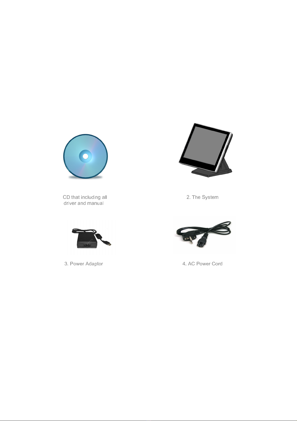
4. Items Checklist
If any item is missing, contact your sale agent immediately.
Take the system unit out from the carton. Remove the unit by carefully holding the foam inserts
and remove slowly to protect the system. The following items should be found in the carton:
CD that including all
driver and manual
2. The S stem
3. Power Adaptor 4. AC Power Cord
EC-15i5 User Manual 7
5. About your system
Unplug the AC power of the adapter before opening any part of the system since the standby power
is always on whenever the adapter is plugged in. It may cause permanent damage to your system
when you open any part of it.
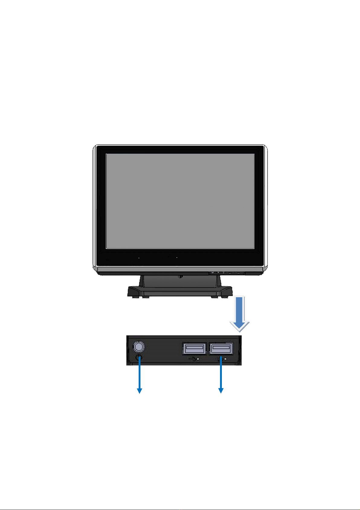
Front View
Power
Button
USB 2.0
EC-15i5 User Manual 8
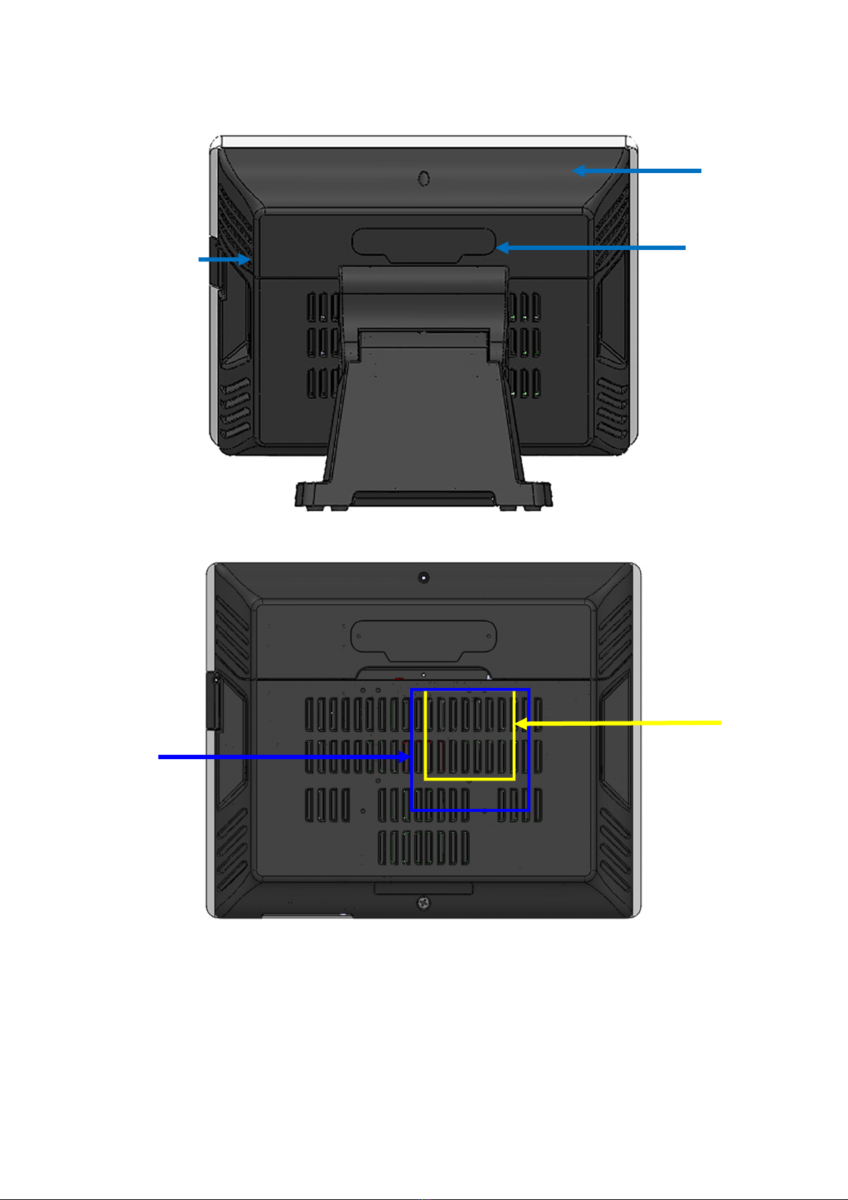
Rear View
Slot for installing
Magnetic Card
Reader (Optional)
Cable Cover
Slot for installing
Custom Display or
Second Display
(Optional)
VESA 75
VESA 100

EC-15i5 User Manual 9
How to open the connector bezel
How to open the connector bezelHow to open the connector bezel
How to open the connector bezel
Unplug the AC power of the adapter before opening any part of the system since the standby power
is always on whenever the adapter is plugged in. It may cause permanent damage to your system
when you open any part of it.
As illustrated in the
following
Move these two sides upward
Release the screw

EC-15i5 User Manual 10
The connector panel
1. TOP of machine
2. Bottom of machine
Hard Disk
2
Power IN
Earphone
Microphone
USB 3.0
USB 2.0
VGA
AN
COM3
COM4
PS/2
Power Button
USB 2.0
COM1
COM2 RJ11
Hard Disk
1
EC-15i5 User Manual 11
6. Setting up your System
Unplug the AC power of the adapter before opening any part of the system since the standby power
is always on whenever the adapter is plugged in. It may cause permanent damage to your system
when you open any part of it.
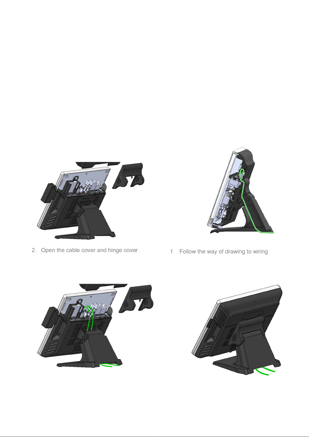
Installing Peripherals
Installing Peripherals Installing Peripherals
Installing Peripherals
To install the peripheral’s cables, please follow the below.
2.
Open the cable cover and hinge cover
1. Follow the way of drawing to wiring
3. Plug in all the cable on the ports 4. Through the cable between hinge and foot

EC-15i5 User Manual 12
In talling
In talling In talling
In talling Magnetic Card R
Magnetic Card RMagnetic Card R
Magnetic Card Reader (MSR)
eader (MSR)eader (MSR)
eader (MSR)
1. Remove the rubber mat. Loosen the screw and
remove the MSR cover
2. Connected to the cable on the MSR and host, then lock two screws
1
2

EC-15i5 User Manual 13
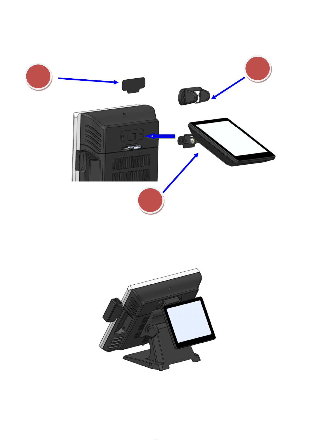
Installing
Installing Installing
Installing Customer Display
Customer DisplayCustomer Display
Customer Display
1
2
1. Remove the metal bezel
2. Connected to the cable, lock the two screws on cable cover
3. Installation VFD cover and lock the two screws
Note: Provides VFD DC + 5V .
If use COM3, see Page 72, COM4, see Page 71
If use COM1, COM2, change UART1 and UART2 RI Function , see Page 32
EC-15i5 User Manual 14
Installing Second Display
Replace and Installing Hard Disk
1. Remove the metal bezel
2. Connected the cable, lock the two screws on cable cover
. Installation VFD cover and lock the two screws
1
2

EC-15i5 User Manual 15
Replace and Installing Memory
1. Release the screw
4.
Grab the handle and pull up or down
Remove or Installation hard disk
2. Move these two sides upward
3. Release the screw
EC-15i5 User Manual 16
1
2
1. Release the screw
2. Grasp the both sides, and pulled down the back cover
3. Replace or Install the memory

EC-15i5 User Manual 17
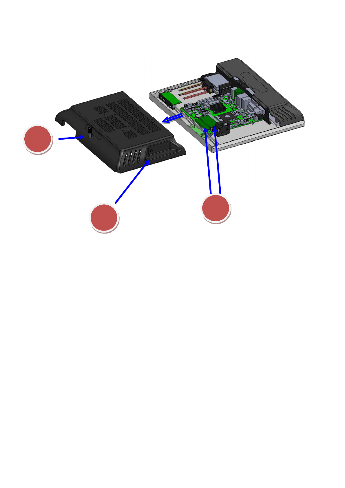
Installing WIFI Card and Antenna
1
2
1. Release the screw
2. Grasp the both sides, and pulled down the back cover
5. Install WIFI Card
Lock 2 screws
3. Remove the plastic pad on the both sides of the Main cover
4. Install Antenna

EC-15i5 User Manual 18
7. BIOS Setting
Introduction
The following is to describe the settings in the AMI UEFI BIOS Setup program on this motherboard.
The Setup program allows users to modify the basic system configuration and save these settings
to NVRAM.
UEFI BIOS determines what a computer can do without accessing programs from a disk. This
system controls most of the input and output devices such as keyboard, mouse, serial ports
and disk drives. BIOS activates at the first stage of the booting process, loading and executing the
operating system. Some additional features, such as virus and password protection or chipset fine-
tuning options are also included in UEFI BIOS.
The rest of this manual will to guide you through the options and settings in UEFI BIOS Setup.
Plug and Play Support
This AMI UEFI BIOS supports the Plug and Play Version 1.0A specification
EPA Green PC Support
This AMI UEFI BIOS supports Version 1.03 of the EPA Green PC specification
ACPI Support
AMI ACPI UEFI BIOS support Version 1.0/2.0 of Advanced Configuration and Power interface
specification (ACPI). It provides ASL code for power management
and device configuration capabilities as defined in the ACPI specification, developed by Microsoft,
Intel and Toshiba
PCI Bus Support
This AMI UEFI BIOS also supports Version 2.3 of the Intel PCI (Peripheral Component Interconnect)
local bus specification
DRAM Support
DDR3 SDRAM (Double Data Rate III Synchronous DRAM) is supported
Supported CPUs
This AMI UEFI BIOS supports the latest CPU
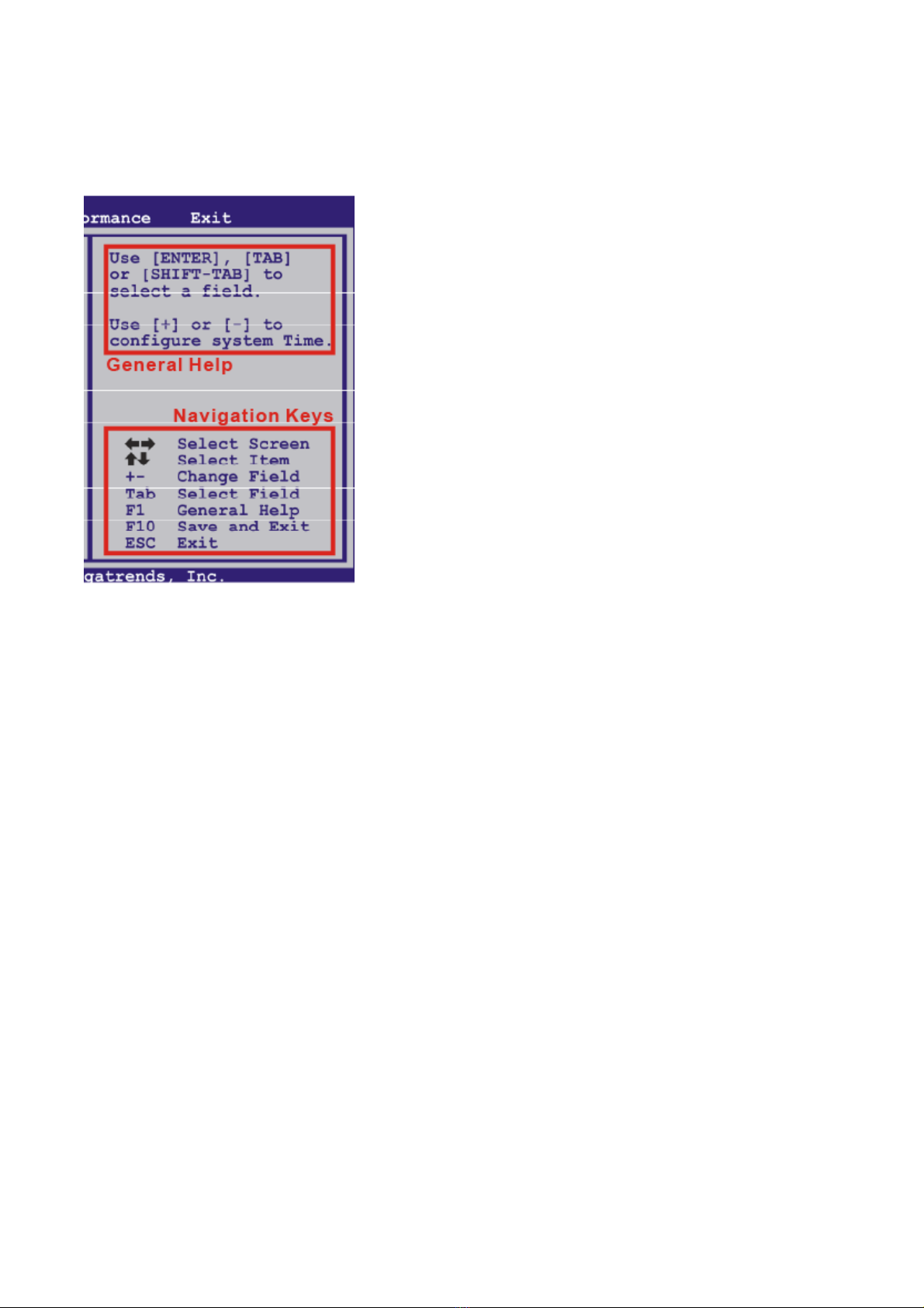
Using Setup
When starting up the computer, press <Del> during the Power-On Self-Test (POST) to enter the
UEFI BIOS setup utility. In the UEFI BIOS setup utility, it can find the General Help description at
the top right corner, and this is providing a brief description of the selected item. Navigation Keys for
EC-15i5 User Manual 19
that particular menu are at the bottom right corner, and you can use these keys to select item
and change the settings
▶
▶▶
▶
Note
The default UEFI BIOS settings apply for most conditions to ensure optimum performance of the
motherboard. If the system becomes unstable after changing any settings, please load the
default settings to ensure system’s compatibility and stability. Use Load Setup Default under the
Exit Menu
For better system performance, the UEFI BIOS firmware is being continuously updated. The
UEFI BIOS information described in this manual is for your reference only. The actual UEFI BIOS
information and settings on board may be slightly different from this manual
The content of this manual is subject to be changed without notice. We will not be responsible
for any mistakes found in this user’s manual and any system damage that may be caused by
wrong-settings
Table of contents
Other EcLine Touch Terminal manuals

EcLine
EcLine EC-1553 User manual

EcLine
EcLine EC-1519 User manual

EcLine
EcLine EC-1200 User manual

EcLine
EcLine EC-VP-3100 User manual

EcLine
EcLine EC-AM-102-58 User manual

EcLine
EcLine EC-AM-102 User manual

EcLine
EcLine EC-1219 User manual

EcLine
EcLine EC-1519I3 User manual

EcLine
EcLine EC-VP-1100 User manual

EcLine
EcLine EC-VP-1100A User manual


