ECO Schulte SR BGX User manual

1/12
Leistungserklärung nach Verordnung (EU) Nr. 305/2011 finden Sie unter http://www.eco-schulte.de/leistungserklaerungen
Declaration of performance according to Regulation (EU) No 305/2011 see http://www.eco-schulte.de/declarationofperformance
Déclaration des performances conformément au règlement (UE) N° 305/2011 voir http://www.eco-schulte.de/declarationdesperformances
Only original parts have to be used. The assembly has to be made by a qualified person according to the mounting instruction. In case of
non-respect the guarantee is invalid. This instruction is to be handed over to the operator by the fitter after assembly!
Impérativement utiliser la notice de montage fournie par le fabricant. La mise en œuvre et le montage doivent être exécutés par du person-
nel qualifié. Le non respect de ces règles annule catégoriquement tout droit de garantie. Cette instruction est à remettre par le poseur
à l’exploitant après montage.
Für die Montage dürfen ausschließlich Originalteile des Herstellers verwendet werden. Die Montagearbeiten müssen gemäß Anleitung von
einer qualifizierten Person durchgeführt werden. Bei Nichtbeachtung entfällt jeglicher Garantieanspruch. Diese Anleitung ist vom Monteur
nach der Montage an den Betreiber weiterzugeben!
Abkürzungen
Schließ-
geschwindigkeit
SG
ES
ÖD
SK
Endschlag
Öffnungs-
dämpfung
Schließkraft
CS
Abbreviations Abréviations
Closing speed
LS
BC
CF
Latching speed
Back check
Closing force
Vitesse de
fermeture
VF
CF
FO
FF
Coup final
Frein á
l’ouverture
Force de
fermeture
SV Schließ-
verzögerung DA Delay action TF Temporisation à
la fermeture
1100 mm +6
1250 mm +11
TS-62 G
EN 2-5
2850 mm -2
950 mm 0
Türschließergröße
Door closer size
Force du ferme-portes
Max. Türbreite
Max. door width
Largeur de porte max.
Umdrehungen
Rotations
Rotations
3
4
5
GS
DIN links - spiegelbildlich
DIN left - mirror image
DIN gauche - inverser l´illustration
max.
3,5mm
© ECO Schulte GmbH & Co. KG / Änderungen vorbehalten! / SR BGX mit TS-62 G / MTS00452 / 33920000452 / Index:
Montageanleitung / Assembly instruction / Notice de montage
SR BGX mit TS-62 G
SR BGX with TS-62 G
SR BGX avec TS-62 G
(DIN rechts / DIN links spiegelbildlich)
(DIN right / DIN left mirror image)
(DIN droite / DIN gauche inverser l‘illustration)

2/12
1a
446120 446 120
142 160 142160
G
60,5
S
A
428,5
18
27
A
428,5
69
Bohrungen für Mitnehmerklappe MK Basis 2
Drillings for panic flap MK Basis 2
Perçage pour entraineur à l'ouverture MK Basis 2
8030
25
446 120446120
142160142 160
G
60,5
S
A
428,5
18
A
428,5
27
69
80 30
25
Bohrungen für Mitnehmerklappe MK Basis 2
Drillings for panic flap MK Basis 2
Perçage pour entraineur à l'ouverture MK Basis 2
16 65
53
X
X = 70-105mm
M5x20
4,5x35
Montageanleitung / Assembly instruction / Notice de montage
SR BGX mit TS-62 G
SR BGX with TS-62 G
SR BGX avec TS-62 G
(DIN rechts / DIN links spiegelbildlich)
(DIN right / DIN left mirror image)
(DIN droite / DIN gauche inverser l‘illustration)

3/12
142160142 160
GS
A
223
446 120
291 58260,5 26069
18
A
27
69
80 30
25
Bohrungen für Mitnehmerklappe MK Basis 2
Drillings for panic flap MK Basis 2
Perçage pour entraineur à l'ouverture MK Basis 2
142 160 142160
G S
A
223 446120 291
582 60,5260 69
18
27
69
A
8030
25
Bohrungen für Mitnehmerklappe MK Basis 2
Drillings for panic flap MK Basis 2
Perçage pour entraineur à l'ouverture MK Basis 2
16 65
53 19
X
X = 70-105mm
1b (optional, optional, optionnelle)
M5x20
4,5x35
M5x12
Montageanleitung / Assembly instruction / Notice de montage
SR BGX mit TS-62 G
SR BGX with TS-62 G
SR BGX avec TS-62 G
(DIN rechts / DIN links spiegelbildlich)
(DIN right / DIN left mirror image)
(DIN droite / DIN gauche inverser l‘illustration)

4/12
1c
16 84
716
X
X = 80-105mm
33
<
GS
223
446 120
291 52260,5 26069
142160
142 160
A
60
30
18
A
58
69
80 30
Bohrungen für Mitnehmerklappe MK Basis 2
Drillings for panic flap MK Basis 2
Perçage pour entraineur à l'ouverture MK Basis 2
G S
223 446120 291
522 60,5260 69
142 160 142160
A
60 30
18
58
A
69
8030
Bohrungen für Mitnehmerklappe MK Basis 2
Drillings for panic flap MK Basis 2
Perçage pour entraineur à l'ouverture MK Basis 2
1c
(optional, optional, optionnelle)
M5x12
M5x20
4,5x35
Montageanleitung / Assembly instruction / Notice de montage
SR BGX mit TS-62 G
SR BGX with TS-62 G
SR BGX avec TS-62 G
(DIN rechts / DIN links spiegelbildlich)
(DIN right / DIN left mirror image)
(DIN droite / DIN gauche inverser l‘illustration)

5/12
4
2
3
1
M6x20
1
M6x20 3
3
2
SW 2,5
2
SW 2,5
M5x20
4,8x30
M5x20
4,8x30
M5x20
4,5x35
M5x12
**nur bei Direktmontage
direct mounting only
seulement en cas de
montage direct
Montageanleitung / Assembly instruction / Notice de montage
SR BGX mit TS-62 G
SR BGX with TS-62 G
SR BGX avec TS-62 G
(DIN rechts / DIN links spiegelbildlich)
(DIN right / DIN left mirror image)
(DIN droite / DIN gauche inverser l‘illustration)

6/12
5
6
1
SW 2,5
2
SW 5
SW 2,5
1
2
3
SW 5
1
SW 2,5
34
SW 2,5
7
1
2
1
SW 2,5
M5x42
M5x42
Montageanleitung / Assembly instruction / Notice de montage
SR BGX mit TS-62 G
SR BGX with TS-62 G
SR BGX avec TS-62 G
(DIN rechts / DIN links spiegelbildlich)
(DIN right / DIN left mirror image)
(DIN droite / DIN gauche inverser l‘illustration)

7/12
8
max.
1
2.1
Ymax 8mm
3mm
A
5mm
B
Xmax 2mm
+
2.2
Den Winkel erst im Objekt vor Ort, nach abgeschlossener Justierung der Standflügelgleitschiene, anschrauben!
After the end of adjustment of the sliding rail for inactive leaf, mount the angle on the construction site!
Après la fin de l'ajustement de la glissière pour vantail semi-fixe, montez l'equerre sur le chantier!
10°-0°
ES/LS/CF
1
213
4
213
4
2
+
+
3
25
TS-62 G
+11
-2
0
+6
EN
3
4
5
mm
950
850
1100
1250
SK/CF/FF
Einstellungen Türschließer
Adjustments of the door closer
Reglages du ferme - portes
Abkürzungen
SK
ES
ÖD
SG
Endschlag
Öffnungs-
dämpfung
Schließkraft CF
Abbreviations Abréviations
Closing speed
LS
BC
CS
Latching speed
Back check
Closing force
Vitesse de
fermeture
FF
CF
FO
VF
Coup final
Frein à
l’ouverture
Force de
fermeture
Schließ-
geschwindigkeit
SV DA Delay action TF Temporisation à
la fermeture
Schließ-
verzögerung
10
9
11
SG/CS/VF
ca.70°-0°
2
G
GS
Montageanleitung / Assembly instruction / Notice de montage
SR BGX mit TS-62 G
SR BGX with TS-62 G
SR BGX avec TS-62 G
(DIN rechts / DIN links spiegelbildlich)
(DIN right / DIN left mirror image)
(DIN droite / DIN gauche inverser l‘illustration)

8/12
X
1
15
X -3 mm
2
G
SV/DA/TF
95°-70°
4
GS
213
4
G
ÖD/BC/FO
70°-ca.95°
3
GS
213
4
Türstopper setzen
Place door stopper
Placer butoir de porte
12 13
14
S
G
ca.95° ca.95°
3
90°
4
Montageanleitung / Assembly instruction / Notice de montage
SR BGX mit TS-62 G
SR BGX with TS-62 G
SR BGX avec TS-62 G
(DIN rechts / DIN links spiegelbildlich)
(DIN right / DIN left mirror image)
(DIN droite / DIN gauche inverser l‘illustration)

9/12
2
1
2
1
12
18
Y
1
3
4
17
Y -8 mm
25
4
Funktionsprüfung SR
Functional test SR
Test fonctionnel SR
16
1
SW2,5
2x
2
SW2,5
2x
Montageanleitung / Assembly instruction / Notice de montage
SR BGX mit TS-62 G
SR BGX with TS-62 G
SR BGX avec TS-62 G
(DIN rechts / DIN links spiegelbildlich)
(DIN right / DIN left mirror image)
(DIN droite / DIN gauche inverser l‘illustration)

10/12
2
3
4
1a
1b
1c
5
7
6
17
18
16
1313
15
14
9
8
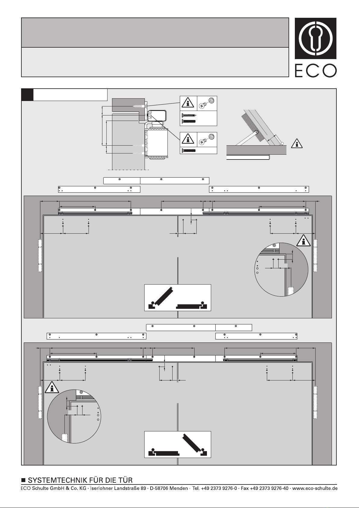
Montageprofile und Montageplatten (optional) anschrauben, gegebenenfalls bei Überlappung in Türmitte kürzen.
Normalmontage
Türschließer montieren.
Gleitbock auf Anschlag schieben . Auslösewinkel auf Anschlag an die Rolle montieren .
Wichtig: Der maximale Zargenüberstand beträgt 2mm, darüber sind die Distanzplatten a oder b zu verwenden.
Der maximale Zargenüberstand mit Platten beträgt 8mm, darüber bitte Anfragen.
12
34
Schließgeschwindigkeitsventile schließen . Gang- und Standflügel öffnen . Durch Öffnen des Standflügels
auf ca. 40° wird die Gleitschiene in die endgültige Montageposition geschoben . Madenschrauben festziehen .
12
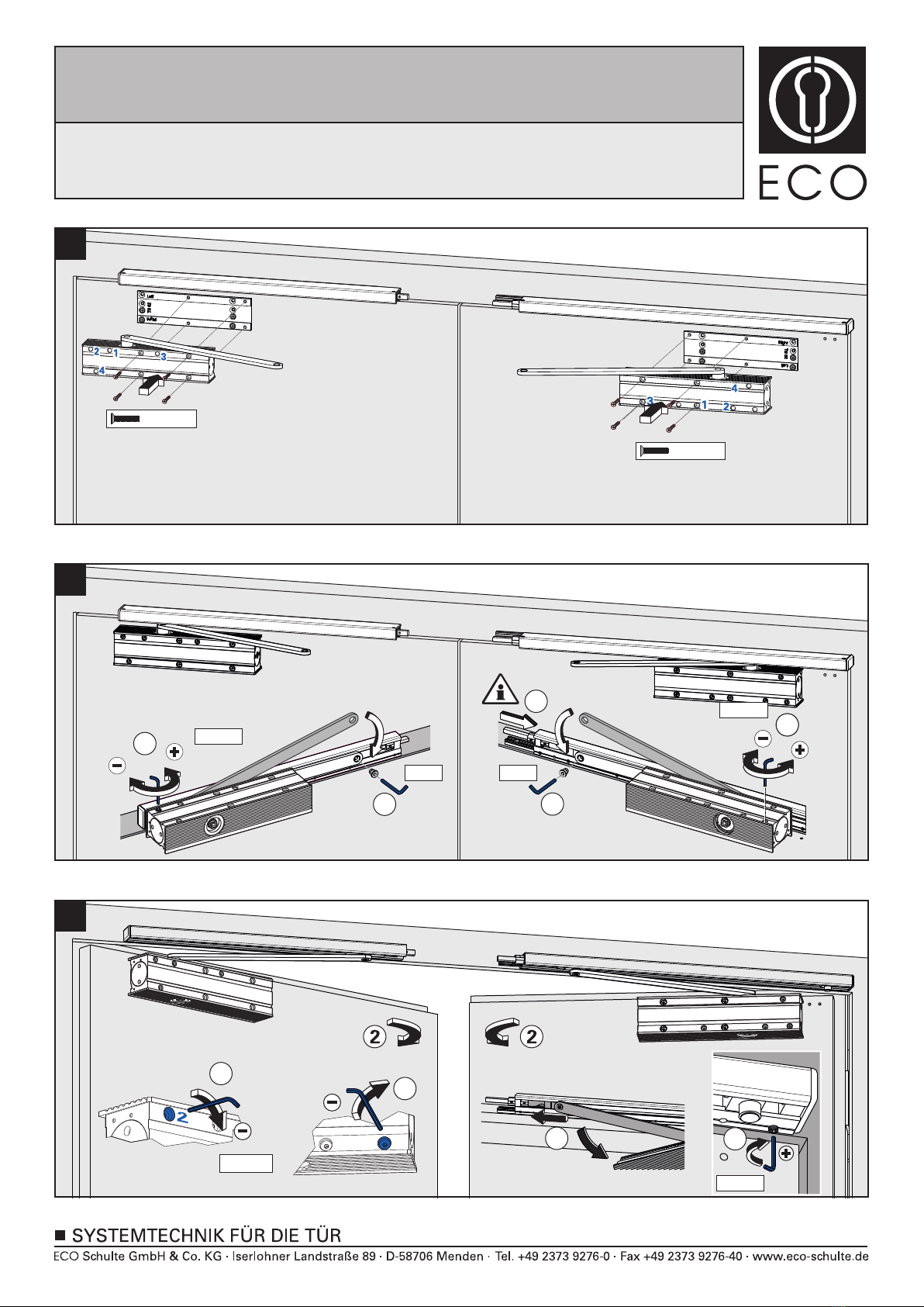
Durch Öffnen des Schließgeschwindigkeitsventils den Hebelarm Richtung Tür führen. Hebelarm mit Gleit-
schuh verbinden . Wichtig: Standflügelgleitschiene auf Anschlag in Richtung Gleitschuh schieben .
23
1
Gleitschienen auf das Montageprofil einhängen. Gangflügelgleitschiene in Pfeilrichtung auf Anschlag schieben
1
. Madenschrauben festziehen . Wichtig: Madenschrauben der Standflügelgleitschiene noch nicht festziehen!
2
1
Vorbereitung Schließer: Hebelarme wie dargestellt montieren . Schließgeschwindigkeitsventile schließen .
Hebelarme vorspannen .
3
2
Montage mit Sturzfutterwinkel
Sturzfutterwinkel entsprechend Anbaumaßen montieren. Montage gemäß fortführen.
2 18
Montage mit Adaptionsprofil
Adaptionsprofile entsprechend Anbaumaßen montieren. Montage gemäß fortführen.
2 18
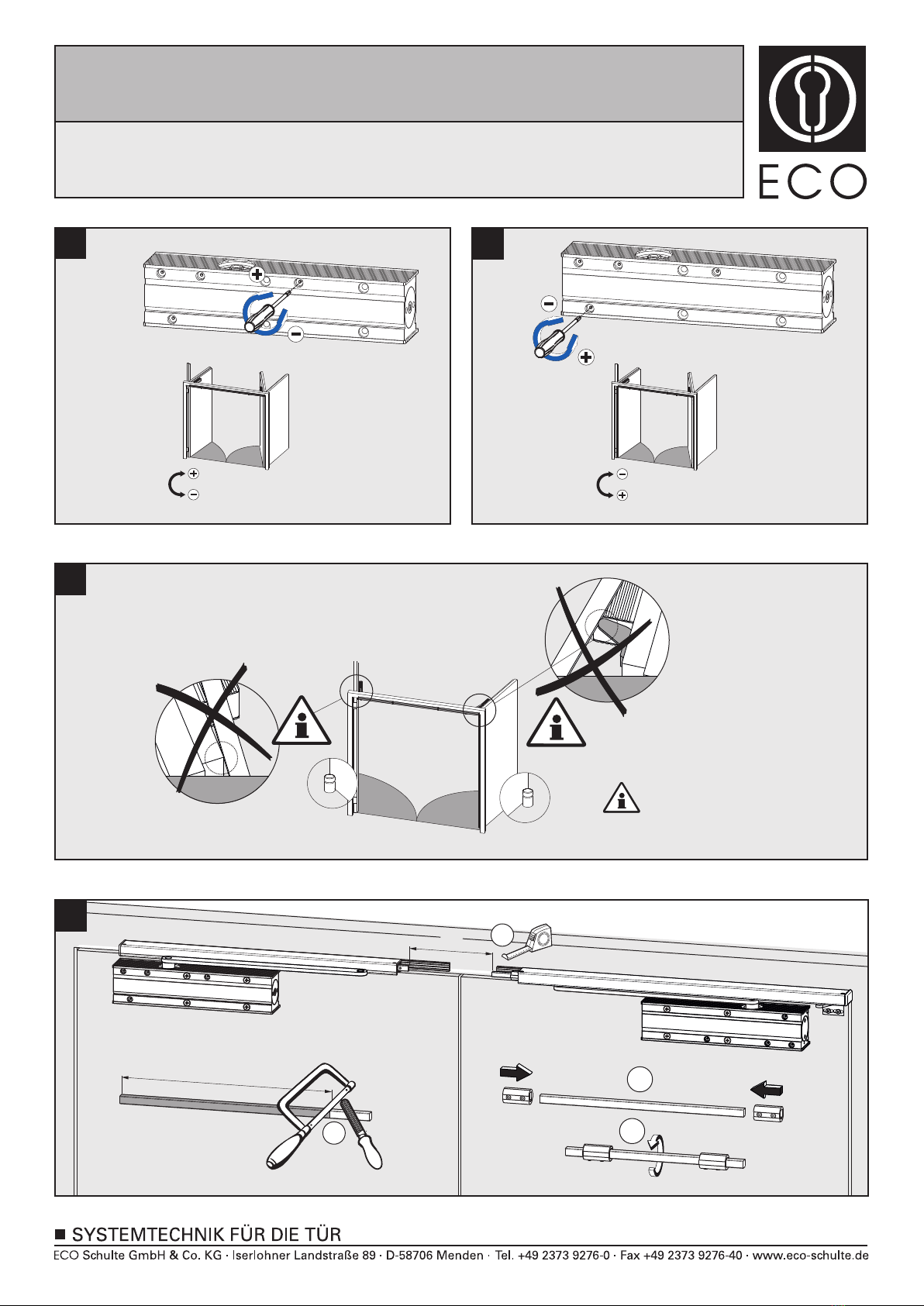
Abhängig von den baulichen Gegebenheiten und der vorhandenen Türstärke beträgt der maximale
Öffnungswinkel ca. 95°. Um Beschädigungen der Türen bzw. der Türschließer zu vermeiden, ist am
maximalen Öffnungswinkel ein Türstopper zu setzen! (Gang- und Standflügel)
1
23
Funktionsprüfung:
Beide Türflügel ca. 60° öffnen, Gangflügel muß geöffnet bleiben. Standflügel schließt. Gangflügel darf erst ab
einem Schließwinkel des Standflügels von ca. 30° schließen.
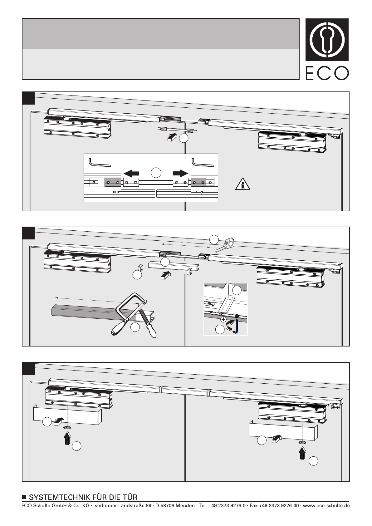
Verbindungsstange zwischen die Stangenenden führen . Die Verbindungsmuffen über die Stangenenden auf
Anschlag schieben und Madenschrauben festziehen .
1
2
Maß X gemäß Darstellung ermitteln . Verbindungsstange auf entsprechendes Maß X -3mm ablängen und
entgraten .Verbindungsmuffen wie dargestellt auf die Verbindungsstange schieben .
U-Cover und Ritzelabdeckung aufklippen.
4
Maß Y gemäß Darstellung ermitteln . Abdeckprofil auf entsprechendes Maß Y -8mm ablängen und entgraten .
Abdeckprofil auf das Montageprofil einhängen . Kunststoff-Clips einsetzen . Abdeckprofil ausrichten und
fixieren .
1
5
2
2
3
1
3
Schließkraft, Schließgeschwindigkeit, Endschlag, Öffnungsdämpfung und Schließverzögerung einstellen.
-
Im Folgenden wird die Montage für Gangflügel DIN rechts gezeigt. Bei Gangflügel DIN links bitte entsprechend vorgehen.
Montageanleitung / Assembly instruction / Notice de montage
SR BGX mit TS-62 G
SR BGX with TS-62 G
SR BGX avec TS-62 G
(DIN rechts / DIN links spiegelbildlich)
(DIN right / DIN left mirror image)
(DIN droite / DIN gauche inverser l‘illustration)

11/12
2
3
4
1a
1b
1c
5
7
6
17
18
16
1313
15
14
9
8
-
Assembly for active leaves on the right is described below. For active leaves on the left, please go on accordingly.
Standard mounting
Mounting with adaptor profile
Mounting with under-lintle angle
Mount adaptor profiles acc. to mounting dimensions. Go ahead with mounting acc. to .
Mount under-lintle angle acc. to mounting dimensions. Go ahead with mounting acc. to .
2 18
2 18
Screw on mounting profiles and mounting plates (optional) , if necessary cut in the door middle.
Fix the slide rail to the mounting profile. Move the slide rail of the active leaf in the direction of the arrow until
it reaches the stop . Tighten screws . Important: do not yet tighten the screws of the passive leaf slide rail.
12
Preparation door closer: Mount arm as shown . Close valves for closing speed . Preload arms .
123
Mount door closer.
Move the arm in the direction of the door by opening the valve for the closing speed . Connect arm to sliding
block . Important: move slide rail of passive leaf towards the maximum direction of the sliding block .
1
23
Close the valves for closing speed . Open both door leafs . By opening the passive leaf to approximately 40°,
the slide rail will be moved into the final mounting position . Tighten the screws .
12
34
Move sliding block until stop . Mount triggering angle at stop on the roll . Important: maximum projection
length of door frame is 2mm, otherwise use distance plates a or b. The maximum projection length of door frame
with distance plates is 8mm, all other lengths on request.
12
Adjust closing force, closing speed, latching speed, back check and delay action.
The maximum opening angle of the active leaf is about 95° depending on the constructional condition and the
door thickness. In order to avoid damages on doors and / or door closers, please set a door stop at the
maximum opening angle (active and passive leaf).
Determine dimension x acc. to drawing . Cut to length the connection rod to dimension x-3mm and deburr
the connection rod . Put the connection sleeves over the connection rod .
1
23
Move connection rod towards both rod ends . Put connection sleeves over the rod ends until stop and tighten
screws .
12
3
Open both doors approx. 60°, active leaf has to remain open. Passive leaf closes. Active leaf is only allowed to
close if the passive leaf reaches a closing angle of approx. 30°.
Clip on U-Cover and pinion cover .
12
Determine dimension y acc. to drawing . Cut to length the U-cover profile to dimension y-8mm and deburr
the cover profile . Attach cover profile to mounting profile . Attach nylon clips . Adjust and fix cover profile .
1
2345
Montageanleitung / Assembly instruction / Notice de montage
SR BGX mit TS-62 G
SR BGX with TS-62 G
SR BGX avec TS-62 G
(DIN rechts / DIN links spiegelbildlich)
(DIN right / DIN left mirror image)
(DIN droite / DIN gauche inverser l‘illustration)

12/12
2
3
4
1a
1b
1c
5
7
6
17
18
16
1313
15
14
9
8
-
Montage avec profil d’adaptation
Montage standard
Monter le profil d’adaptation selon la configuration. Montage .
2 18
Monter l‘équerre selon la configuration. Montage .
Montage sous linteau avec équerre
2 18
Visser le profil et la plaque de montage (option), si nécessaire recouper au milieu de la porte.
Fixer la glissière sur le profil.Glisser la glissière du vantail principal jusqu’en butée dans le sens de la flèche.
Serrer les vis six pans . Important: ne pas vissser les vis six pans de la glissère du vantail secondaire.
1
2
Préparation du ferme-portes. Monter le bras de levier comme indiqué . Serrer la vis de réglage de la vitesse
de fermeture . Fixer le bras de levier .
1
23
Monter les ferme-portes.
Desserrer la vis de réglagle de la vitesse de fermeture . Fixer le bras de levier au patin de la glissière .
Important: Glisser la glissière du vantail secondaire en butée vers le patin .
12
3
Serrer la vis de réglage de la vitesse de fermeture . Ouvrir les deux vantaux . Lors de l’ouverture à 40° la
glissière du vantail secondaire atteindra sa position finale . Serrer les vis six pans .
12
34
Faire glisser le patin à rouleau de la glissière en butée . Monter l’équerre jusqu’au rouleau .
Important: Recouvrement maximum 2mm, si plus utiliser les cales a (3mm) ou b (5mm). Au-delà de 8mm de
recouvrement, nous consulter.
12
Régler la vitesse de fermeture, l’à-coup final, le frein à l’ouverture, la temporisation à la fermeture et la force
de fermeture.
Selon les informations fournies et selon l’épaisseur de la porte, l’angle d’ouverture du vantail est de 95°.
Il est conseillé de fixer une butée au sol pour chaque vantail.
Mesurer la côte X . Recouper la tige de liaison X -3mm . Glisser les manchons sur la tige comme indiqué .
123
Positionner la tige entre les glissières . Faire glisser les manchons sur les carrés des glissières et serrer
les vis six pans .
12
3
Ouvrir les deux vantaux à 60°, le vantail principal doit rester en position ouverte. Le vantail secondaire se
referme. Le vantail principal ne doit se refermer qu’à partir du moment où le vantail secondaire a
atteint 30°.
Mesurer la côte X . Recouper le profil de recouvrement X -8mm , positionner le profil ainsi que les deux
pièces de finition en nylons - . Fixer le tout .
12
345
12
Clipser le capot U du ferme-portes ainsi que le cache de l’axe .
Ci-dessous le montage pour vantail principal droite. Pour le montage à gauche veuillez procéder en conséquence.
Montageanleitung / Assembly instruction / Notice de montage
SR BGX mit TS-62 G
SR BGX with TS-62 G
SR BGX avec TS-62 G
(DIN rechts / DIN links spiegelbildlich)
(DIN right / DIN left mirror image)
(DIN droite / DIN gauche inverser l‘illustration)
Other ECO Schulte Door Opening System manuals

ECO Schulte
ECO Schulte FSA ECO SR-EFR User manual

ECO Schulte
ECO Schulte ECO EF User manual

ECO Schulte
ECO Schulte ECO SR-EF User manual

ECO Schulte
ECO Schulte FH842 User manual

ECO Schulte
ECO Schulte SR BG III User manual

ECO Schulte
ECO Schulte ETS 42 User manual

ECO Schulte
ECO Schulte FSA ECO SR-EFR User manual

ECO Schulte
ECO Schulte EF BG User manual
Popular Door Opening System manuals by other brands

Amazon
Amazon B07GDXCX87 manual

Chamberlain
Chamberlain K001D8398-1 Power board replacement

DITEC
DITEC Entrematic Hurricane DS20 Installation and service manual

Assa Abloy
Assa Abloy Rixson Smok-Chek VI Installation and instruction manual

Assa Abloy
Assa Abloy SARGENT 281 Series manual

Yale
Yale YDC201 installation instructions