Ecoflo Water Ace WASBB User manual
Owner’s Manual
12 Volt Battery Backup
Sump Pump System
General Safety . . . . . . . . . . . . . . . . . 2 & 3
Contents & Tools. . . . . . . . . . . . . . . . . . . 4
Installation. . . . . . . . . . . . . . . . . . . . 4 & 6
Parts. . . . . . . . . . . . . . . . . . . . . . . . . . . . 5
Testing & Operation . . . . . . . . . . . . . . . . 7
Warranty. . . . . . . . . . . . . . . . . . . . . . . . . 8
TABLE OF CONTENTS
General Safety
Risk of burns. Do not touch
an operating motor. Motors are designed to op-
erate at high temperatures. To avoid burns when
servicing pump, allow it to cool for 20 minutes
after shut-down before handling.
Do not allow pump or any system component to
freeze. To do so will void warranty.
Pump water only with this pump.
Periodically inspect pump and system
components.
Wear safety glasses at all times when working
on pumps.
Risk of explosion. Pump
body may explode if used as a booster pump.
Avoid exposing controls or
batterytoanyopenameor
sparks. Batteries can generate explosive gases.
2
A sump pump is an electrical device designed to
operate in inherently wet environments.
ALWAYS USE EXTREME CAUTION
when installing or maintaining this product!
Need Help: Call 1-844-394-2604 for assistance;
Do Not Return to Store
Important Safety Instructions
Carefully read and follow all safety
instructions in this manual and on pump.
SAVE THESE INSTRUCTIONS – This manual
contains important instructions that should be
followed during installation, operation, and
maintenance of the product.
Save this manual for future reference.
Safety Labels
This is the safety alert symbol. When you
see this symbol on your pump or in this manual,
look for one of the following signal words and be
alert to the potential for personal injury!
Indicates a hazard which, if
not avoided, will result in death or serious injury.
Indicates a hazard which,
if not avoided, could result in death or serious
injury.
Indicates a hazard which, if
not avoided, could result in minor or moderate
injury.
NOTICE indicates practices not related to
personal injury.
Keep safety labels in good condition. Replace
missing or damaged safety labels.
GENERAL SAFETY
STOP Before you start

Provide proper ventilation. The battery enclo-
sures should be designed to prevent accumu-
lation and concentration by hydrogen gas in
“pockets” at the top of the compartment. Vent
the battery compartment from the highest point.
Aslopedlidcanalsobeusedtodirecttheow
to the vent opening location. To reduce the risk
of the battery explosion, follow all the instruc-
tions of the battery supplier or any equipment
you intend to use in the vicinity of batteries.
Use the correct insulated
tools to make AC/DC
wiring connections.
Do not install battery/controls
onornearammablemateri-
als (plywood, chemicals, gas online etc.)
Personal Precautions:
Someone should be within
the range of your voice to
come to your aid when you work near batteries.
Have plenty of fresh water
and soap nearby in the event
that battery acid contact skin, clothing or eyes.
Wear complete eye and
clothing protection.
Avoid touching eyes while
working near batteries. Wash
your hands when done.
If battery acid comes in
contact with skin or clothing,
wash immediately with soap and water.
KNOWING YOUR SYSTEM
The battery pack acts as a reserve to ensure
continuous supply of power whenever mains
supply from utility power is not available. The
controls are used to charge the batteries when
normal utility power is available and converts the
battery’s DC to AC voltage to run the pump when
utility power is lost.
BATTERY SAFETY
A battery can present a risk of severe burn and
injury from high short circuit current. The follow-
ing precautions should be observed when work-
ing on batteries.
1.Donotdisposeofbatteryinare.Thebattery
may explode.
3
2. Do not open or mutilate the battery. Released
electrolyte is harmful to the skin and eyes. It
may be toxic.
3. The electrolyte is a dilute sulfuric acid that is
harmful to the skin and eyes. It is electrically
conductive and corrosive. The following
procedures should be observed:
a.Ifelectrolytecontactstheskin,washito
immediately.
b.Ifelectrolytecontactstheeyes,ush
thoroughly and immediately with water. Seek
medical attention.
c. Spilled electrolyte should be washed down
with a suitable acid neutralizing agent. A
common practice is to use a solution of
approximately one pound (500 grams)
bicarbonate of soda to approximately one
gallon (4 liters) of water. The bicarbonate
of soda solution be added until the evidence
of reaction (foaming) has ceased. The result
ingliquidshouldbeushedwithwaterand
the area dried.
4. Do not reverse the battery connections, as it
will blow the battery fuse. A power cord has
been provided to connect the controls to an
incoming AC wall outlet.
BATTERY REQUIREMENTS
Your unit operates on 12VDC battery power
when in the power fail mode. A UL recognized
deep cycle marine battery should be used. There
are two principal types of batteries: starting and
deepcycle.Thereareseveraldierenttypesof
battery constitutions including liquid lead acid,
nickel iron, nickel cadmium, alkaline and mainte-
nance free. Batteries can be sealed or vented.
Starting Batteries
Starting batteries are designed for high crank-
ing power but not deep cycling. Do not use them
with your back-up sump pump. They will simply
not last long in a deep cycle application.
Deep Cycle Batteries
Deep cycle batteries are best suited for use with
the battery back-up sump pump. They are de-
signed to have the majority of their capacity used
before recharge. Available in many sizes and
types, be sure to use at least a 80AH battery.
BATTERIES NOT INCLUDED
4
1 - 12 volt battery backup sump pump
1 - Control/alarm panel
1 - Float switch
1 - 12 volt battery charger
1 - Extra fuse
2 - Battery terminal post clamps
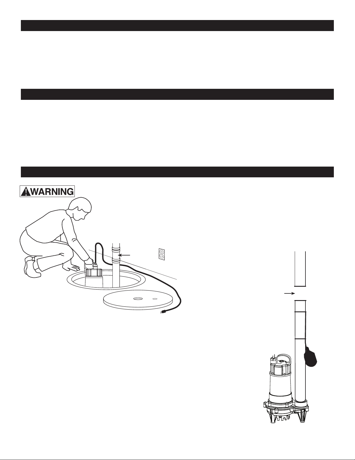
STEP 1:
Disconnect check valve or coupling from the discharge pipe and primary
sump pump. Then remove primary sump pump and pipe assembly from
sump and place in a well lit work area. Re-install check valve at the sump
discharge or base. Be sure check valve is below the back up pump.
STEP 2:
Holdtheautomaticoatswitchupintheonposition.Markthatlocationon
the discharge pipe. From that mark, measure up the pipe 2” and mark the
pipeagain.Atthesecondmark,cutoasectionofthedischargepipeas
described below, to allow space for the supplied pump installation tee.
Ifdischargeis1-1/4”pipe,cuto1-1/2”ofpipe.
Ifdischargeis1-1/2”pipe,cuto2”ofpipe.
TOOLS:
Adjustable wrench or socket wrench
Screwdriver
Hack saw or PVC pipe cutters
File or sandpaper for sanding cut pipe
Clean cloth for wiping water debris
MATERIALS:
PVC cement and primer
One 12 Volt Group 24 Deep Cycle Marine
Battery
2 - Wire ties
1 - Plastic battery case (Battery not included)
1 - Dual pipe size (1-1/2” or 1-1/4”) PVC tee
with a 1” threaded check valve tting for
installing the pump
4 - Mounting screws
DISCONNECT ELECTRICAL POWER FROM PRIMARY SUMP PUMP
Check Valve
Cut out
section of pipe
2”
CONTENTS
TOOLS & MATERIALS NEEDED
INSTALLATION
327.8 [12.92]
ECD25W
ECD33W
ECD50W
221.8[8.73] SWITCH OFF
401.8[15.82] SWITCH ON
ECD75W
REF50W
357.8 [14.10]
251.8[9.91] SWITCH OFF
431.8[17.0] SWITCH ON
{

5
STEP 3:
Thread the Battery Backup Sump Pump onto thedual size pipe tee provided. Once
the pump is threaded tight and oriented parallel to the discharge pipe, turn the pipe
to the 2 o’clock position to prevent air from being trapped in the pump housing.
Then cement the installation tee to the discharge pipe with PVC primer and PVC
cement.
STEP 5:
Attach the automatic
oat switch to the
discharge pipe so that
the switch is tethered
1-1/4” from the dis-
charge pipe. Use the
supplied wire straps
to mount the oat
switch cord to the
discharge pipe.
INSTALLATION
Check
Valve
Backup Pump
Suction Inlet
Float Sensor
Discharge Pipe
1-1/4”
Tether
3
4
5
12
1
2
The top of the Battery Backup Pump
should be at least 4” below the top of the
sump and at least 1” above the highest
water level of the primary sump pump.
Connect the remaining discharge pipes,
check valve and couplings.
STEP 4:
Replace primary
sump pump and
Battery Backup
Pump assembly
into the sump
basin.
REPLACEMENT PARTS
Part Number Description No.
EF091EBBS14 Battery Box* 1
EF091EBBS15 Control 2
EF091EBBS16 12V. Transformer/Plug 3
EF091EBBS17 Pump - 2700GPH 4
EF091EBBS18 Float Switch 5
EF091EBBS19 Inline Tee 6
EF091EBBS20 Check Valve 7
* Battery Box does not include battery or control.
7
6
4
5
2
3
1
6
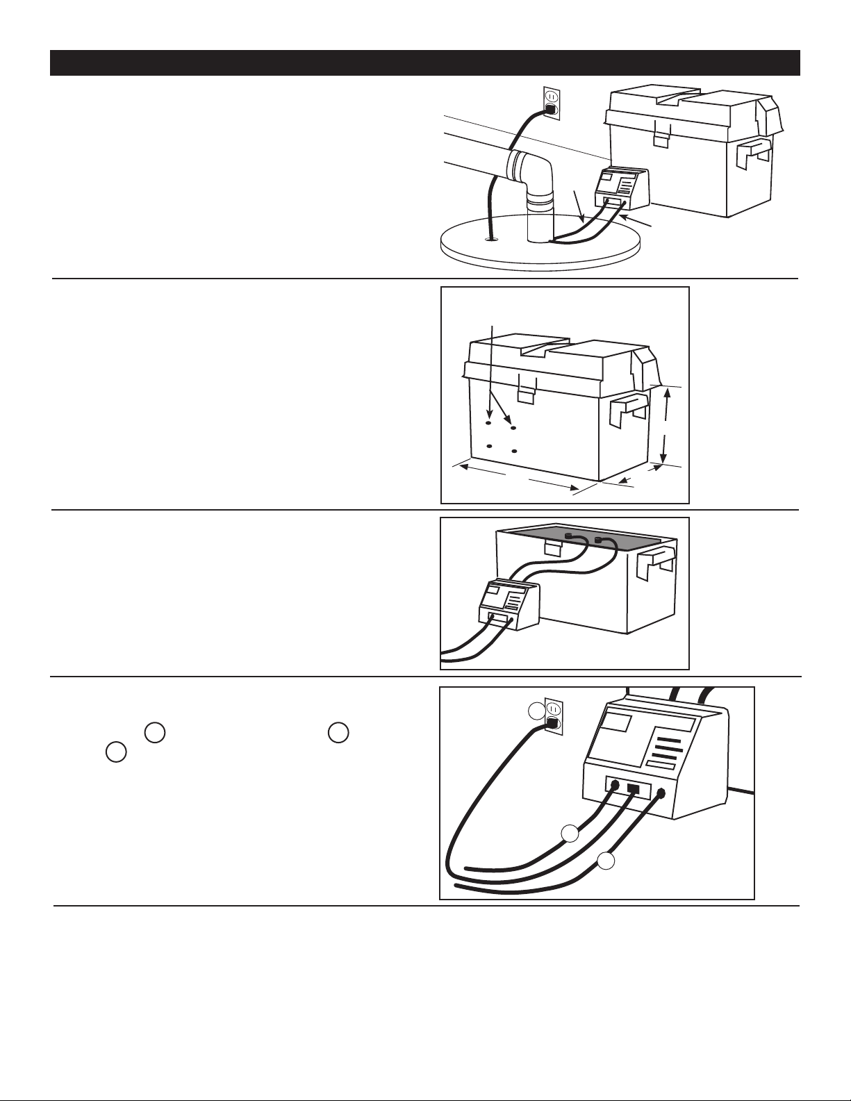
STEP 1:
Mount the Control/Alarm Panel to the battery case
using the four mounting screws provided. Battery
case has four mounting holes predrilled for easy
installation of control panel.
For best results, use a Group 24, marine battery.
Battery dimensions should not exceed : 9” high
(including post) x 12” long x 6-1/2” wide.
YOUR BATTERY BACKUP SUMP PUMP SYSTEM IS READY.
STEP 2:
Insert marine battery into battery case. Attach
the RED and BLACK wires from the back of the
control/alarm panel to each of the battery clamps
provided. Then connect battery clamps to the
battery. RED WIRE to the POSITIVE (+) terminal
and the BLACK WIRE to the NEGATIVE (-)
terminal.
STEP 4:
Turn the alarm switch on the control/alarm panel to the OFF position and plug the 12 volt transformer in a GFCI
outlet. If a GFCI outlet is unavailable, have an electrician install one for you. Once proper power is supplied, turn
the alarm switch to the on position. Then plug the primary sump pump to its power source.
BATTERY & CONTROL/ALARM PANEL ASSEMBLY
STEP 3:
Plug in the designated components to the control/
alarm panel, A battery backup pump, B the oat
switch, C and the 12 volt transformer.
Pre-drilled
Mounting Holes
6 -1/ 2”
12”
9”
B Float Switch
Pump Cord A
Power C
STEP 6:
Feedthepumpandoatswitchcordsthrough
the sump pump vent or utility hole and cover the
sump with the sump cover.
Power
Cord
Float
Switch
Cord

7
STEP 1:
Disconnect the power to the primary sump pump so the only pump available is the Battery Backup Sump Pump.
STEP 2:
With a garden hose or buckets of water ll the sump basin with water. At the designated level of water, the Bat-
tery Backup Sump Pump should activate and the ALARM and ALARM INDICATOR LIGHT should come on. This
indicates the system is working.
STEP 3:
Press the RESET button on the control/alarm panel and reconnect power to the primary sump pump. The test is
complete.
NOTE: If the Battery Backup Sump Pump failed to activate, review the complete instructions.
The Battery Backup Sump Pump is designated as an emergency back up pump in the event your primary sump
pump fails or if there is a loss of power to your primary sump pump.
THE BATTERY BACKUP SUMP PUMP IS NOT INTENDED FOR USE AS A PRIMARY SUMP PUMP.
PRIMARY SUMP PUMP FAILURE
In the event your primary sump pump fails or loses power, the Battery Backup System will automatically activate
when the oat switch reaches the ON position. When it turns on, a alarm will sound and the alarm indicator will
light. When the water in the sump basin recedes and the pump turns off, the alarm will continue to sound until you
depress the ON/OFF switch to the on/off switch to the ON position and press the RESET button.
BATTERY LOW
In the event 12 volt battery charge should drop lower than 11 volts, the alarm will sound and the BATTERY LOW
indicator will light. Press the ON/OFF switch to OFF position, disconnect power to the 12 volt transformer from the
GFCI outlet and disconnect the pump and oat switch cords from the alarm/control panel plugs. Have the bat-
tery checked, serviced or replaced if necessary. Once 12 volt battery is serviced or replaced, reconnect all plugs,
cables and power and follow the Test Procedures listed in this owners manual.
BATTERY CHARGING/CHARGED
When the battery is not at full charge capacity, the BATTERY CHARGING indicator will light. The battery charger
is simply recharging the battery to its full charged capacity. Once the battery has reached full charging capacity
(13 volts) the CHARGED indicator will light.
If neither the BATTERY CHARGING or CHARGED indicator lights are on, check all wire connections and plugs to
ensure proper hook up.
LEADS REVERSED
If you connect the battery cable to the wrong battery terminal, the LEADS REVERSED indicator will light. Simply
remove the battery cable and reconnect to the proper battery terminals. The RED WIRE is connected to the posi-
tive (+) terminal and the BLACK wire is connected to the negative (-) terminal.
You must replace the 1 amp fuse with the extra fuse provided. Simply turn the fuse cover counter clockwise until
the burnt fuse is exposed. Replace the fuse and thread the fuse cover, turning clockwise.
BATTERY MAINTENANCE
The 12 volt marine battery should be tested every four to six months. It is recommended to replace the battery
every three to four years. Follow the battery manufacturers recommendations for proper battery maintenance and
battery replacement.
TESTING THE SYSTEM
NORMAL OPERATION

8
WARRANTY
Retain Original Purchase Receipt for Warranty Eligibility
Limited Warranty
Manufacturer warrants to the original consumer purchaser (“Purchaser” or “You”) that its products are free from defects in
material and workmanship for a period of twelve (12) months from the date of the original consumer purchase. If, within
twelve (12) months from the original consumer purchase, any such product shall prove to be defective, it shall be repaired
or replaced at manufacturer’s option, subject to the terms and conditions set forth herein. Note that this limited warranty
applies to manufacturing defects only and not to ordinary wear and tear. All mechanical devices need periodic parts and
service to perform well. This limited warranty does not cover repair when normal use has exhausted the life of a part or
the equipment.
The original purchase receipt and product warranty information label are required to determine warranty eligibility. Eligibil-
ity is based on purchase date or original product – not the date of replacement under warranty. The warranty is limited to
repair or replacement of original purchased product only, not replacement product (i.e. one warranty replacement allowed
per purchase).
Purchaser pays all removal, installation, labor, shipping, and incidental charges.
Claims made under this warranty shall be made by returning the product to the retail outlet where it was purchased or to
the factory immediately after the discovery or any alleged defect. Manufacturer will subsequently take corrective action as
promptly as reasonably possible. No requests for service will be accepted if received more than 30 days after the warranty
expires. Warranty is not transferable and does not apply to products used in commercial/rental applications.
General Terms and Conditions; Limitations of Remedies
You must pay all labor and shipping charges necessary to replace product covered by this warranty. This warranty does
not apply to the following: (1) acts of God; (2) products which, in manufacturer’s sole judgment, have been subject to
negligence, abuse, accident, misapplication, tampering, or alteration; (3) failures due to improper installation, operation,
maintenance or storage; (4) atypical or unapproved application, use or service; (5) failures caused by corrosion, rust or
other foreign materials in the system, or operation at pressures in excess of recommended maximums.
This warranty sets forth manufacturer’s sole obligation and purchaser’s exclusive remedy for defective products.
MANUFACTURER SHALL NOT BE LIABLE FOR ANY CONSEQUENTIAL, INCIDENTAL, OR CONTINGENT DAMAGES
WHATSOEVER. THE FOREGOING LIMITED WARRANTIES ARE EXCLUSIVE AND IN LIEU OF ALL OTHER EXPRESS
AND IMPLIED WARRANTIES, INCLUDING BUT NOT LIMITED TO IMPLIED WARRANTIES OF MERCHANTABILITY
AND FITNESS FOR A PARTICULAR PURPOSE. THE FOREGOING LIMITED WARRANTIES SHALL NOT EXTEND
BEYOND THE DURATION PROVIDED HEREIN.
Some states do not allow the exclusion or limitation of incidental or consequential damages or limitations on how long an
implied warranty lasts, so the above limitations or exclusions may not apply to You. This warranty gives You specic legal
rights and You may also have other rights which vary from state to state.
1899 Cottage Street
Ashland, Ohio 44805
Telephone: 1-844-394-2604
Table of contents
Other Ecoflo Water Pump manuals

Ecoflo
Ecoflo PUP62 User manual

Ecoflo
Ecoflo EFSUB5-102-1 User manual

Ecoflo
Ecoflo PUP57 User manual

Ecoflo
Ecoflo PUP61 User manual

Ecoflo
Ecoflo EFSWJ5 User manual

Ecoflo
Ecoflo RSE Series User manual

Ecoflo
Ecoflo SUP64 User manual

Ecoflo
Ecoflo SHALLOW WELL User manual

Ecoflo
Ecoflo EPP33 User manual

Ecoflo
Ecoflo CDSP-20 User manual

Ecoflo
Ecoflo E130V6 User manual

Ecoflo
Ecoflo CDSP-20 User manual

Ecoflo
Ecoflo ECD30W User manual

Ecoflo
Ecoflo EFLS10P User manual

Ecoflo
Ecoflo SEP75W User manual

Ecoflo
Ecoflo SPP25W User manual

Ecoflo
Ecoflo PUP60 User manual

Ecoflo
Ecoflo EFWIFI33 User manual

Ecoflo
Ecoflo ESS75V User manual

Ecoflo
Ecoflo SUP55PC User manual


