ECS G41T-M13 User manual

Preface
Preface
Copyright
This publication, including all photographs, illustrations and software, is protected
under international copyright laws, with all rights reserved. Neither this manual, nor
any of the material contained herein, may be reproduced without written consent of
the author.
Version 1.0
Disclaimer
The information in this document is subject to change without notice. The manufac-
turer makes no representations or warranties with respect to the contents hereof and
specifically disclaims any implied warranties of merchantability or fitness for any
particular purpose. The manufacturer reserves the right to revise this publication and
to make changes from time to time in the content hereof without obligation of the
manufacturer to notify any person of such revision or changes.
TrademarkRecognition
Microsoft, MS-DOS and Windows are registered trademarks of Microsoft Corp.
MMX, Pentium, Pentium-II, Pentium-III, Celeron are registered trademarks of Intel
Corporation.
Other product names used in this manual are the properties of their respective
owners and are acknowledged.
FederalCommunicationsCommission(FCC)
This equipment has been tested and found to comply with the limits for a Class B
digital device, pursuant to Part 15 of the FCC Rules. These limits are designed to
provide reasonable protection against harmful interference in a residential installa-
tion. This equipment generates, uses, and can radiate radio frequency energy and, if
not installed and used in accordance with the instructions, may cause harmful inter-
ference to radio communications. However, there is no guarantee that interference
will not occur in a particular installation. If this equipment does cause harmful
interference to radio or television reception, which can be determined by turning the
equipment off and on, the user is encouraged to try to correct the interference by one
or more of the following measures:
• Reorient or relocate the receiving antenna
• Increase the separation between the equipment and the receiver
• Connect the equipment onto an outlet on a circuit different from that to
which the receiver is connected
• Consult the dealer or an experienced radio/TV technician for help
Shielded interconnect cables and a shielded AC power cable must be employed with
this equipment to ensure compliance with the pertinent RF emission limits govern-
ing this device. Changes or modifications not expressly approved by the system’s
manufacturer could void the user’s authority to operate the equipment.

ii
Preface
DeclarationofConformity
This device complies with part 15 of the FCC rules. Operation is subject to the
following conditions:
• This device may not cause harmful interference, and
• This device must accept any interference received, including interfer-
ence that may cause undesired operation
CanadianDepartmentofCommunications
This class B digital apparatus meets all requirements of the Canadian Interference-
causing Equipment Regulations.
Cet appareil numérique de la classe B respecte toutes les exigences du Réglement sur
le matériel brouilieur du Canada.
AbouttheManual
The manual consists of the following:
Chapter 1
Introducing the Motherboard
Chapter 2
Installing the Motherboard
Chapter 3
UsingBIOS
Chapter 4
Using the Motherboard Software
Describes features of the
motherboard.
Go to Hpage 1
Describes installation of motherboard
components.
Go to Hpage 7
Provides information on using the
BIOSSetupUtility.
Go to Hpage 23
Describes the motherboard software.
Go to Hpage 41
Chatper 5
TroubleShooting
Provides basic trouble shooting tips
page 45Go to H

iii
TT
TT
TABLE OF CONTENTSABLE OF CONTENTS
ABLE OF CONTENTSABLE OF CONTENTS
ABLE OF CONTENTS
Preface i
Chapter 1 1
IntroducingtheMotherboard 1
Introduction......................................................................................1
Feature...............................................................................................2
Specification......................................................................................4
MotherboardComponents.............................................................5
Chapter 2 77
77
7
Installing the Motherboard 7
SafetyPrecautions............................................................................7
Choosinga ComputerCase.............................................................7
Installingthe Motherboard in aCase............................................7
CheckingJumperSettings...............................................................8
Setting Jumpers...................................................................8
Checking Jumper Settings...................................................9
Jumper Settings...................................................................9
InstallingHardware........................................................................10
Installing the Processor.....................................................10
Installing Memory Modules...............................................12
Expansion Slots.................................................................13
Connecting Optional Devices............................................15
Installing a SATA Hard Drive..........................................18
ConnectingI/ODevices................................................................19
ConnectingCase Components.....................................................20
Front Panel Header...........................................................22
Chapter 3 2323
2323
23
UsingBIOS 23
Aboutthe SetupUtility................................................................23
The Standard Configuration..............................................23
Entering the Setup Utility....................................................23
Resetting the Default CMOS Values...................................24

iv
Using BIOS......................................................................................25
Standard CMOS Setup..........................................................26
Advanced Setup..................................................................27
Advanced Chipset Setup.....................................................29
Integrated Peripherals........................................................30
Power Management Setup..................................................32
PCI/PnP Setup...................................................................33
PC Health Status................................................................33
Frequency/Voltage Control.................................................37
Load Default Settings.........................................................38
Supervisor Password.........................................................38
User Password...................................................................39
Save & Exit Setup................................................................39
Exit Without Saving.............................................................39
Updating the BIOS...............................................................40
Chapter 4 4141
4141
41
UsingtheMotherboardSoftware 41
AbouttheSoftware DVD-ROM/CD-ROM........................................41
Auto-installingunderWindows XP/Vista/7.....................................41
Running Setup....................................................................42
ManualInstallation...............................................................................44
UtilitySoftwareReference...................................................................44
Chapter 5 4545
4545
45
TroubleShooting 45
Startup problemsduring assembly.......................................................45
Start up problems afterprolong use.................................................46
Maintenanceand caretips..................................................................46
Basic TroubleshootingFlowchart...................................................47

1
IntroducingtheMotherboard
Chapter1
IntroducingtheMotherboard
Introduction
Thank you for choosing the G41T-M13 motherboard. This motherboard is a high
performance, enhanced function motherboard designed to support the LGA775 socket
for CoreTM 2 Extreme/CoreTM 2 Quad/CoreTM 2 Duo/Pentium®Dual Core/Celeron®
Dual Core/Celeron®400/Pentium®4/Celeron®D series processors (Please reference
the CPU support list) for high-end business or personal desktop markets.
The ICH7 Southbridge supports two PCI slots which are PCI v2.3 compliant. In
addition, one PCI Express x1 slot is supported, fully compliant to the PCI Express
Base Specification revision 1.0a. It implements an EHCI compliant interface that
provides 480 Mb/s bandwidth for eight USB 2.0 ports (four USB ports and two USB
2.0 headers support additional four USB ports). The Southbridge integrates a Serial
ATA host controller, supporting four SATA ports with maximum transfer rate up to
3.0 Gb/s each.
The motherboard is equipped with advanced full set of I/O ports in the rear panel,
including PS/2 mouse and keyboard connectors, one VGA port, four USB ports, one
LAN port, and audio jacks for microphone, line-in and line-out.
The motherboard incorporates the Intel®G41 Northbridge (NB) and Intel®ICH7
Southbridge (SB) chipsets. It supports a system bus (FSB) of 1333/1066/800/533
MHz. The memory controller supports DDR3 memory DIMM frequencies of
1333(OC)/1066/800*. It supports two DDR3 sockets with up to maximum memory
of 8 GB. DDR3 Maximum memory bandwidth of 12.8 GB/s in dual-channel symmet-
ric mode assuming DDR3 1333(OC)/1066/800 MHz. One PCI Express x16 slot,
intended for Graphics Interface, is fully compliant to the PCI Express Gen 1.

2
IntroducingtheMotherboard
Feature
The motherboard uses an LGA775 type of CoreTM 2 Extreme/CoreTM 2 Quad/
CoreTM 2 Duo/Pentium®Dual Core/Celeron®Dual Core/Celeron®400/Pentium®
4/Celeron®D series processors that carries the following features:
Processor
•CoreTM 2 Extreme/CoreTM 2 Quad/CoreTM 2 Duo/Pentium®Dual Core/
Celeron®Dual Core/Celeron®400/Pentium®4/Celeron®D series pro-
cessors
• Supports a system bus (FSB) of 1333/1066/800/533 MHz
• LGA775 socket for latest Intel®45nm Multi-Core processors
The Intel®G41 Northbridge (NB) and Intel®ICH7 Southbridge (SB) chipsets are
based on an innovative and scalable architecture with proven reliability and
performance.
Chipset
G41 (NB)
ICH7 (SB)
Memory
• Enhanced DMA Controller, interrupt controller, and timer
functions
• Compliant with PCI Express Base Specification, Revi-
sion 1.0a
• Compliant with PCI v2.3 specification
• Integrated SATA 3.0 Gb/s Host Controller
• Integrated USB 2.0 Host Controller supporting up to
eight USB 2.0 ports
• Supports 36-bit host bus addressing, allowing the CPU to
access the entire 64 GB of the memory address space
• 2 GB/s point-to-point Direct Media Interface (DMI) to
ICH7 (1 GB/s each direction)
• Supports 2-GB, 1-Gb, 512 Mb DDR3 DRAM technolo-
gies for x8 and x16 devices
• One, 16-lane (x16) PCI Express port intended for exter-
nal device attach, fully compatible to the PCI Express
Gen 1
• An integrated graphics device (IGD) delivering cost com-
petitive 3D, 2D and video capabilities
• Microsoft DX10 and 128MB share memory are sup-
ported
• Supports DDR3 1333(OC)/1066/800 DDR3 SDRAM with Dual-channel
architecture.
• Accommodates two unbuffered DIMMs.
• 2 x 240-pin DDR3 DIMM sockets support up to 8 GB.

3
IntroducingtheMotherboard
Onboard LAN (optional)
The motherboard comes with the following expansion options:
• One PCI Express x16 slots for Graphic Interface
• One PCI Express x1 slot
• Two 32-bit PCI v2.3 compliant slots
• Four 7-pin SATA connectors
Expansion Options
• Two PS/2 ports for mouse and keyboard
• One VGA port
• Four USB 2.0 ports
• One LAN port
• Audio jacks for microphone, line-in and line-out
The motherboard has a full set of I/O ports and connectors:
Integrated I/O
• Compliants with PCI Express. 1.1
• Integrated 10/100 transceiver
• Supports Wake-on-LAN and remote wakeup
• Fullycompliantwith IEEE 802.3, IEEE802.3u
Audio
This motherboard may support either of the following Audio chipsets:
• 5.1 Channel High Definition Audio Codec
• Exceeds Microsoft Windows Logo Program (WLP) Requirements
• ADCs support 44.1K/48K/88.2K/96K/192KHz sample rate
• Power Support: Digital: 3.3V; Analog: 5.0V
1.Some hardware specifications and software items are subject to change
without prior notice.
2.Due to chipset limitation, we recommend that motherboard be oper-
ated in the ambiance between 0 and 50°C.
The firmware can also be used to set parameters for different processor clock
speeds.
• Power management
• Wake-up alarms
• CPUparameters
• CPUandmemorytiming
BIOS Firmware
This motherboard uses AMI BIOS that enables users to configure many system
features including the following:
• Compliants with PCI Express. 1.1
• Integrated 10/100/1000 transceiver
• Supports Wake-on-LAN and remote wakeup
• FullycompliantwithIEEE802.3, IEEE802.3u, IEEE802.3ab

4
IntroducingtheMotherboard
• Intel G41 & ICH7 Express Chipset
North Bridge: Intel G41 South Bridge: ICH7
• LGA775 socket for CoreTM 2 Extreme/CoreTM 2 Quad/CoreTM
2Duo/Pentium®DualCore/Celeron®DualCore/Celeron®400/
Pentium®4/Celeron®D series processors
• Dual-channel DDR3 memory architecture
• 2 x 240-pin DDR3 DIMM sockets support up to 8 GB
• Supports DDR3 1333(OC)/1066/800 SDRAM
• 1 x PCI Express x16 slot
• 1 x PCI Express x1 slot
• 2 x PCI slots
• Supported by Intel ICH7 Express Chipset
• 4 x Serial ATA 3.0 Gb/s devices
• 1 x Ultra DMA100/66 port
• VIA VT1705 6-Ch High Definition audio CODEC
• Realtek 8105E 10/100 Lan (Realtek 8111E Giga Lan Op-
tional)
• 1 x PS/2 keyboard & PS/2 mouse connectors
• 1 x VGA port
• 4 x USB 2.0 ports
• 1 x RJ45 LAN connector
• 1 x Audio port (Line in, microphone in, line out)
Chipset
Memory
Expansion
Slots
Storage
Audio
LAN
RearPanelI/O
InternalI/O
Connectors &
Headers
• AMIBIOS with 8MbSPI Flash ROM
• Supports Plug and Play, STR(S3)/STD(S4), Hardware moni-
tor, Multi Boot
• SupportsACPI&DMI
• Audio, LAN can be disabled in BIOS
• F11 hot key for boot up devices option
SystemBIOS
FormFactor • MicroATX Size, 244mm x 170mm
CPU
Specifications
• 1 x 24-pin ATX power supply connector
• 1 x 4-pin 12V Power connector
• 1 x 4-pin CPU_FAN connector
• 1 x Speaker header
• 1 x Front panel audio header
• 1 x Front panel switch/LED header
• 1 x SPDIF out header
• 1 x Serial port header (COM)
• 4 x SATA 3Gb/s connectors
• 2 x USB 2.0 headers
• 1 x Chassis intrusion header
• 1 x Parallel port header (LPT)
• 1 x CLR_CMOS header

5
IntroducingtheMotherboard
MotherboardComponents
6
IntroducingtheMotherboard
Table of Motherboard Components
This concludes Chapter 1. The next chapter explains how to install the motherboard.
LABEL COMPONENTS
1. CPU Socket LGA775 socket for CoreTM 2 Extreme/CoreTM 2 Quad/
CoreTM 2 Duo/Pentium® Dual Core/Celeron®Dual Core/
Core/Celeron®400/Pentium®4/Celeron®D series
p
rocessors
2. CPU_FAN CPU cooling fan connector
3. DDR3_1~2 240-pin DDR3 SDRAM slots
4. ATX_POWER Standard 24-pin ATX power connector
5. SATA3~4 Serial ATA connectors
6. SPK Speaker header
7. CLR_CMOS Clear CMOS jumper
8. USBPWR_F Front panel USB power select jumper
9. SATA1~2 Serial ATA connectors
10. F_USB1~2 Front panel USB headers
11. F_PANEL Front panel switch/LED header
12. COM Onboard serial port header
13. SPDIFO SPDIF out header
14. LPT Onboard parallel port header
15. F_AUDIO Front panel audio header
16. PCI1~2 32-bit add-on card slots
17. PCIE PCI Express x 1 slot
18. CASE Chassis intrusion header
19. PCIEX16 PCI Express x16 graphics card slot
20. USBPWR_R Rear panel USB/PS2 power select jumper
21. ATX12V 4-pin +12V power connector

7
InstallingtheMotherboard
Chapter2
InstallingtheMotherboard
SafetyPrecautions
• Follow these safety precautions when installing the motherboard
• Wear a grounding strap attached to a grounded device to avoid dam-
age from static electricity
• Discharge static electricity by touching the metal case of a safely
grounded object before working on the motherboard
• Leave components in the static-proof bags they came in
• Hold all circuit boards by the edges. Do not bend circuit boards
ChoosingaComputerCase
There are many types of computer cases on the market. The motherboard complies
with the specifications for the Micro ATX system case. First, some features on the
motherboard are implemented by cabling connectors on the motherboard to indica-
tors and switches on the system case. Make sure that your case supports all the
features required. Secondly, make sure that your case has sufficient power and space
for all drives that you intend to install.
Most cases have a choice of I/O templates in the rear panel. Make sure that the I/O
template in the case matches the I/O ports installed on the rear edge of the
motherboard.
This motherboard carries a Micro ATX form factor of 244 x 170 mm. Choose a case
that accommodates this form factor.
InstallingtheMotherboard in a Case
Refer to the following illustration and instructions for installing the motherboard in
a case.
Most system cases have mounting brackets installed in the case, which correspond
the holes in the motherboard. Place the motherboard over the mounting brackets
and secure the motherboard onto the mounting brackets with screws.
Ensure that your case has an I/O template that supports the I/O ports and expansion
slots on your motherboard.

8
InstallingtheMotherboard
CheckingJumperSettings
This section explains how to set jumpers for correct configuration of the motherboard.
SettingJumpers
Use the motherboard jumpers to set system configuration options. Jumpers with
more than one pin are numbered. When setting the jumpers, ensure that the jumper
caps are placed on the correct pins.
The illustrations show a 2-pin jumper.
When the jumper cap is placed on both
pins, the jumper is SHORT. If you re-
move the jumper cap, or place the jumper
cap on just one pin, the jumper is OPEN.
This illustration shows a 3-pin jumper.
Pins 1 and 2 are SHORT.
SHORT OPEN
Do not over-tighten the screws as this can stress the motherboard.

9
InstallingtheMotherboard
Checking Jumper Settings
The following illustration shows the location of the motherboard jumpers. Pin 1 is
labeled.
JumperSettings
Jumper Type Description Setting (default)
CLR_CMOS 3-pin CLEAR CMOS
1-2: NORMAL
2-3: CLEAR
Before clearing the
CMOS, make sure to
turn the system off.
3-pin
USBPWR_R 1-2: VCC
2-3: 5VSB
Rear USB/PS2
Power Select
Jumper
3-pinUSBPWR_F 1-2: VCC
2-3: 5VSB
Front Panel
USB Power
Select Jumper USBPWR_F
CLR_CMOS
USBPWR_R
1
1
1
To avoid the system instability after clearing CMOS, we recommend
users to enter the main BIOS setting page to “Load Default Settings”
and then “Save & Exit Setup”.
1.
2. Make sure the power supply provides enough 5VSB voltage before se-
lecting the 5VSB function.
3. It is required that users place the USBPWR_F & USBPWR_R cap onto
2-3 pin rather than 1-2 pin as default if you want to wake up the com-
puter by USB/PS2 KB/Mouse.

10
InstallingtheMotherboard
InstallingHardware
Caution: When installing a CPU heatsink and cooling fan make sure
that you DO NOT scratch the motherboard or any of the surface-
mount resistors with the clip of the cooling fan. If the clip of the cooling
fan scrapes across the motherboard, you may cause serious damage
to the motherboard or its components.
On most motherboards, there are small surface-mount resistors near
the processor socket, which may be damaged if the cooling fan is
carelessly installed.
Avoid using cooling fans with sharp edges on the fan casing and the
clips. Also, install the cooling fan in a well-lit work area so that you
can clearly see the motherboard and processor socket.
Before installing the Processor
This motherboard has an LGA775 socket. When choosing a processor, consider the
performance requirements of the system. Performance is based on the processor
design, the clock speed and system bus frequency of the processor, and the quantity
of internal cache memory and external cache memory.
2. Always remove the AC power by unplugging the power cord from
the power outlet before installing or removing the motherboard or
other hardware components.
Warning:
1. Over-clocking components can adversely affect the reliability of the
system and introduce errors into your system. Over-clocking can per-
manently damage the motherboard by generating excess heat in com-
ponents that are run beyond the rated limits.
Fail-Safe Procedures for Over-clocking
Installing the Processor
This motherboard automatically determines the CPU clock frequency and system
bus frequency for the processor. You may be able to change the settings in the system
Setup Utility. We strongly recommend that you do not over-clock processors or
other components to run faster than their rated speed.
When end-users encounter failure after attempting over-clocking, please take the
following steps to recover from it.
1. Shut down the computer.
2. Press and hold the “Page Up Key (PgUp)” of the keyboard, and then boot the PC
up.
3. Two seconds after the PC boots up, release the “Page Up Key (PgUp)”.
4. The BIOS returns to the default setting by itself.

11
InstallingtheMotherboard
A. Read and follow the instructions shown
on the sticker on the CPU cap.
B. Unload the cap
· Use thumb & forefinger to hold the
lifting tab of the cap.
· Lift the cap up and remove the cap
completely from the socket.
C. Open the load plate
· Use thumb & forefinger to hold the
hook of the lever, pushing down and
pulling aside unlock it.
· Lift up the lever.
· Use thumb to open the load plate. Be
careful not to touch the contacts.
D. Install the CPU on the socket
· Orientate CPU package to the socket.
Make sure you match triangle marker
to pin 1 location.
E. Close the load plate
· Slightly push down the load plate onto
the tongue side, and hook the lever.
· CPU is locked completely.
F. Apply thermal grease on top of the CPU.
G. Fasten the cooling fan supporting base
onto the CPU socket on the motherboard.
H. Make sure the CPU fan is plugged to the
CPU fan connector. Please refer to the
CPU cooling fan user’s manual for more
detail installation procedure.
CPU Installation Procedure
The following illustration shows CPU installation components.
1. To achieve better airflow rates and heat dissipation, we suggest
that you use a high quality fan with 3800 rpm at least. CPU fan and
heatsink installation procedures may vary with the type of CPU fan/
heatsink supplied. The form and size of fan/heatsink may also vary.
2. DO NOT remove the CPU cap from the socket before installing a
CPU.
3. Return Material Authorization (RMA) requests will be accepted
only if the motherboard comes with the cap on the LGA775 socket.

12
InstallingtheMotherboard
Installing Memory Modules
This motherboard accommodates two memory modules. It runs at dual-channel
DDR3 1333(OC)/1066/800MHz memory speed. The total memory capacity is 8
GB.
You must install at least one module in any of the two slots.
Do not remove any memory module from its antistatic packaging until
you are ready to install it on the motherboard. Handle the modules
only by their edges. Do not touch the components or metal parts.
Always wear a grounding strap when you handle the modules.
Installation Procedure
Refer to the following to install the memory modules.
1 This motherboard supports unbuffered DDR3 SDRAM .
2 Push the latches on each side of the DIMM slot down.
3 Align the memory module with the slot. The DIMM slots are keyed with
notches and the DIMMs are keyed with cutouts so that they can only be
installed correctly.
4 Check that the cutouts on the DIMM module edge connector match the
notches in the DIMM slot.
5 Install the DIMM module into the slot and press it firmly down until it
seats correctly. The slot latches are levered upwards and latch on to
the edges of the DIMM.
6 Installany remaining DIMM modules.
DDR3 SDRAM memory module table
DDR3 800 400 MHz
Memory module Memory Bus
DDR3 1066 533 MHz
DDR3 1333(OC) 667 MHz
13
InstallingtheMotherboard
Installing Add-on Cards
The slots on this motherboard are designed to hold expansion cards and connect
them to the system bus. Expansion slots are a means of adding or enhancing the
motherboard’s features and capabilities. With these efficient facilities, you can in-
crease the motherboard’s capabilities by adding hardware that performs tasks that are
not part of the basic system.
Before installing an add-on card, check the documentation for the card
carefully. If the card is not Plug and Play, you may have to manually
configure the card before installation.
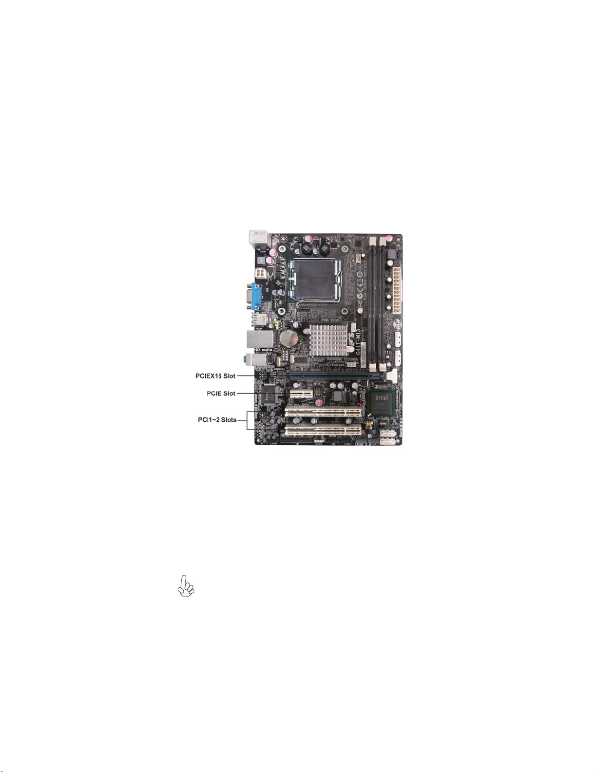
This motherboard is equipped with two standard PCI slots. PCI
stands for Peripheral Component Interconnect and is a bus standard
for expansion cards, which for the most part, is a supplement of the
older ISA bus standard. The PCI slot on this board is PCI
v2.3compliant.
PCI1~2
Slots
PCIEX16 Slot
The PCI Express x1 slot is fully compliant to the PCI Express Base
Specification revision 1.0a.
The PCI Express slot is used to install an external PCI Express
graphics card that is fully compliant to the PCI Express Gen 1.
PCIE Slot
Expansion Slots
14
InstallingtheMotherboard
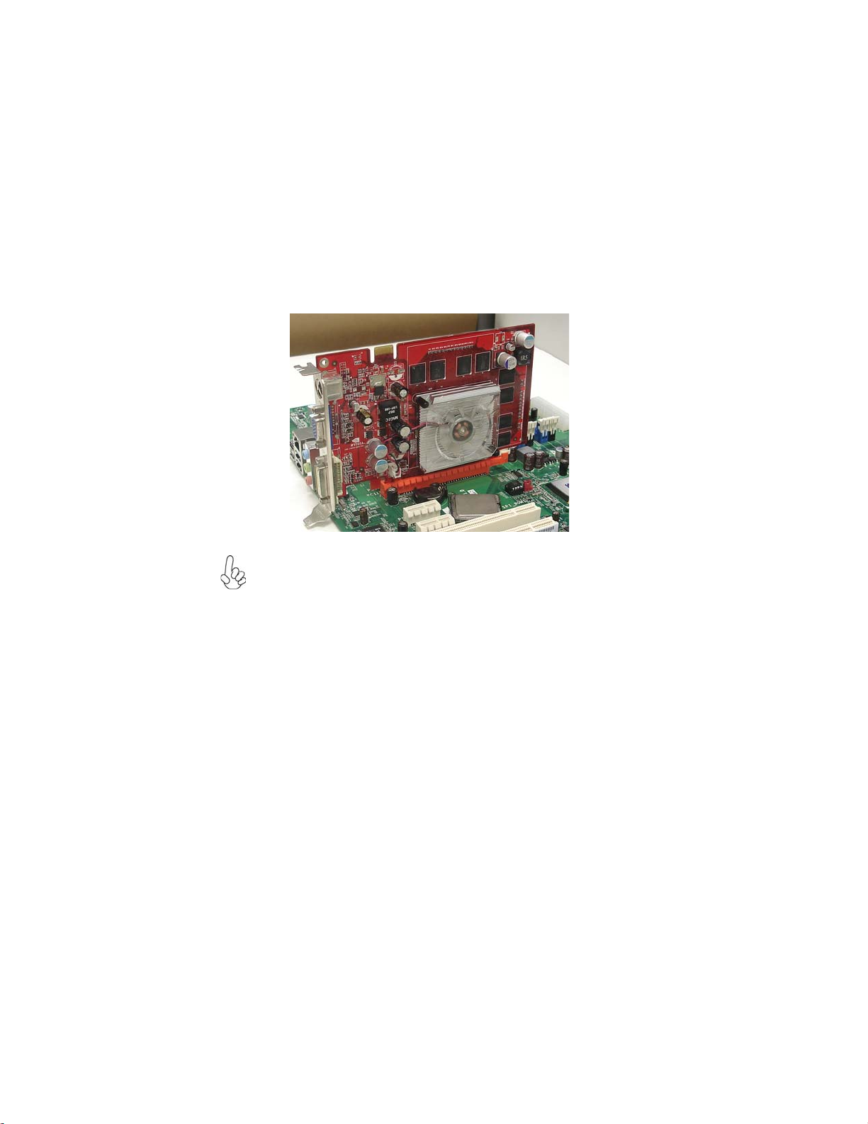
Follow these instructions to install an add-on card:
1 Remove a blanking plate from the system case corresponding to the
slot you are going to use.
2 Install the edge connector of the add-on card into the expansion slot.
Ensure that the edge connector is correctly seated in the slot.
3 Secure the metal bracket of the card to the system case with a screw.
2. The onboard PCI interface does not support 64-bit SCSI cards.
1. For some add-on cards, for example graphics adapters and network
adapters, you have to install drivers and software before you can begin using
the add-on card.

15
InstallingtheMotherboard
Connecting Optional Devices
Refer to the following for information on connecting the motherboard’s optional
devices:
SATA1~4: SerialATAconnectors
These connectors are used to support the new Serial ATA devices for the highest data
transfer rates (3.0 Gb/s), simpler disk drive cabling and easier PC assembly. It elimi-
nates limitations of the current Parallel ATA interface. But maintains register com-
patibility and software compatibility with Parallel ATA.
F_AUDIO:Front Panel Audio header for Azalia
This header allows the user to install auxiliary front-oriented microphone and line-
out ports for easier access.
1Ground 2 TX+
3TX- 4 Ground
5RX- 6 RX+
7Ground - -
Pin Signal NamePin Signal Name
1PORT 1L 2AUD_GND
3PORT 1R 4PRESENCE#
5PORT 2R 6SENSE1_RETURN
7SENSE_SEND 8KEY
Pin Signal Name Pin Signal Name
9PORT 2L 10 SENSE2_RETURN

16
InstallingtheMotherboard
F_USB1~2: Front Panel USB headers
The motherboard has four USB ports installed on the rear edge I/O port array.
Additionally, some computer cases have USB ports at the front of the case. If you
have this kind of case, use auxiliary USB connector to connect the front-mounted
ports to the motherboard.
Please make sure that the USB cable has the same pin assignment as
indicated above. A different pin assignment may cause damage or system
hang-up.
1USBPWR Front Panel USB Power
2USBPWR Front Panel USB Power
3USB_FP_P0- USB Port 0 Negative Signal
4USB_FP_P1- USB Port 1 Negative Signal
5USB_FP_P0+ USB Port 0 Positive Signal
6USB_FP_P1+ USB Port 1 Positive Signal
7GND Ground
8GND Ground
9Key No pin
10 USB_FP_OC0 Overcurrent signal
Pin Signal Name Function
COM: Onboard serial port header
Connect a serial port extension bracket to this header to add a second serial port to
your system.
SPDIFO:SPDIF out header
This is an optional header that provides an S/PDIF (Sony/Philips Digital Interface)
output to digital multimedia device through optical fiber or coaxial connector.
Pin Signal Name Function
1SPDIF SPDIF digital output
2+5VA 5V analog Power
3Key No pin
4GND Ground
1DCDB Data Carrier Detect
2SINB Serial Input
3SOUTB UART B Serial Output
4DTRB UART B Data Terminal Ready
5GND Ground
6DSRB Data Set Ready
7RTSB RART B Request to Send
8CTSB Clear to Send
9RI Ring Indicator
10 Key No pin
Pin Signal Name Function
Table of contents
Other ECS Motherboard manuals


