EDAN INSTRUMENTS SE-3 User manual

EDAN INSTRUMENTS, INC.
Manual Ver: V1.3
Release Date: Aug. 2008
Part Number: MS1R-20094-V1.3
SE
-
3 3
-

-I-
Copyright
Copyright EDAN INSTRUMENTS, INC. 2008.All rights reserved.
Statement
Edan Instruments, Inc. (hereinafter called EDAN) makes no warrantyofanykind with regard to
this material, including,but not limited to the implied warranties of merchantabilityand fitness
for aparticular purpose. EDAN assumes noresponsibilityforanyerrorthat mayappear in this
document, or for incidental or consequential damageinconnection with the furnishing,
performance or use of this material.
No part of this document maybephotocopied,reproduced or translated to another language
without prior written consent of EDAN.
All information contained in this publication is believed to be correct. EDAN shall not be liable
for errors contained herein nor for incidental orconsequential damages inconnection with the
furnishing,performance,or use of this material. This publication mayrefer to information and
protected bycopyrights or patents and does not conveyanylicense under the patent rights of
this company,nor the rights of others. This companydoes not assume anyliabilityarisingout of
anyinfringements of patents or other rights of third parties.
The information contained in this document is subject to changewithout notice.
Responsibility of the Manufacturer
EDAN onlyconsiders itself responsible for anyeffect on safety,reliabilityand performance of
the equipment if:
Assemblyoperations, extensions, re-adjustments, modifications or repairs are carried out by
persons authorized byEDAN, and
The electrical installation of the relevant room complies with national standards, and
The instrument is used in accordance with the instructions for use.
NOTE:This device is not intended for home use.
WARNING :This device is not intended for treatment.
Upon request, EDAN mayprovide, with compensation, necessarycircuitdiagrams, and other
information to help qualified technician to maintain and repair some parts, which EDAN may
define as user serviceable.

-II-
Using This Label Guide
This guide is designed togive keyconcepts on safetyprecautions.
WARNING
A WARNING label advises against certain actions or situations that could result in personal
injuryor death.
CAUTION
A CAUTION label advises against actions or situations that could damage equipment, produce
inaccurate data, or invalidate a procedure.
NOTE: A NOTE provides useful information regardinga function or a procedure.

-III-
Table of Contents
Chapter1 General......................................................................................................................1
1.1 Function Features............................................................................................................1
1.2 Environment Requirement..............................................................................................2
1.3 Power SupplyRequirement.............................................................................................2
Chapter2Appearance Views....................................................................................................3
2.1 Top Panel.........................................................................................................................3
2.2 Patient Cable Socket and Signal Interface......................................................................3
2.3 Mains Connection and Switch.........................................................................................5
2.4 Bottom Panel...................................................................................................................5
Chapter3 Principle....................................................................................................................6
3.1 Abstract of theoryof ECG operation...............................................................................6
3.2 Composition of ECG.......................................................................................................6
3.3 Lead.................................................................................................................................7
3.4 Hardware Design Principle Description..........................................................................9
3.4.1 ECG Board description.......................................................................................10
3.4.2 Main control part description..............................................................................11
3.4.3 Power control part description............................................................................12
Chapter4 Tests.........................................................................................................................13
4.1 System Tests..................................................................................................................13
4.2 Application System Tests..............................................................................................13
4.3 Safety Tests....................................................................................................................15
Chapter5 Electrocardiograph Servicing...............................................................................16
5.1 DisassemblySteps.........................................................................................................16
5.2 Internal Boards and Interfaces.......................................................................................19
5.3 Troubleshooting.............................................................................................................23
Chapter6 Electrocardiograph Installation............................................................................27

-IV-
6.1 Power and Earthing.......................................................................................................27
6.2 Loading/ReplacingRecord Paper..................................................................................28
6.3 Patient Cable Connection..............................................................................................29
6.4 Electrodes Connections.................................................................................................30
6.5 Inspection before Power On..........................................................................................32
Chapter7 Cleaning..................................................................................................................34
7.1 Clean..............................................................................................................................34
7.1.1 Clean the Main Unit and Patient Cable...............................................................34
7.1.2 Clean the Electrodes............................................................................................34
7.1.3 Clean the Print Head...........................................................................................34
7.2 Disinfection...................................................................................................................35
Chapter8 Maintenance...........................................................................................................36
8.1 Recharge and Replacement of Battery..........................................................................36
8.2 Record Paper..........................................................................................................37
8.3 Maintenance of MainUnit, Patient Cable & Electrodes........................................37
Chapter9 Technical Specifications.........................................................................................39

SE-3 3-Channel Electrocardiograph Service Manual
-1-
Chapter 1 General
SE-3 is 3-channel electrocardiographs with 12 leads gatheredsimultaneously,visual displayof
operation menu, ECG parameters as well as electrocardiogram.
3-channel ECG can beviewed on the LCD(liquid crystal display)screen ofSE-3 simultaneously.
And it can be recorded byhigh-qualitythermal recorder.
Manual, automatic, rhythm recordingmode and USB print mode can be chosen conveniently.
Either mains supplyor built-in rechargeable Lithium batterycan be used as power.
With ahighresolution thermal printer,32-bit processor and huge capacitymemorizer,SE-3 has
advanced performance and highreliability.And the compact size makes it suitable for clinic,
hospital and ambulance use.
Configurations:Main unit and accessories (power cord, earth wire, patient cable, electrodes and
thermal recordingpaper)
Note: It is not designed for internal use and direct cardiac application.
1.1 Function Features
♦Low weight and compactsize
♦Touch keyfor easyoperation
♦High resolution thermal recorder, recordingfrequencyresponse ≤150Hz
♦12-lead gathered and amplified simultaneously, 3-channel built-in recorder
♦Automatic mode, manualmode, rhythm mode andUSB print mode optional
♦Measurement function and interpretation function optional
♦LOGIN/PRINT/GENERAL/SYSTEM menu forparameters setting (Onlyfor the device
with 320×240 dot single color LCD Screen)
♦Built-in rechargeable Libatterywith highcapacity
♦Hint information for leadoff, lack of paper and low batterycapacityetc.
♦Automatic adjustment of baseline for optimal recording

SE-3 3-Channel Electrocardiograph Service Manual
-2-
♦Standard input/output interface and RS232 communication interface for linking to
special network and settingup ECG database
1.2 Environment Requirement
The environment requirements are listed in the followingtable.
Transport & Storage Working
Temperature: -20 ~+55 5~40
Relative
Humidity: 25%~93%
(Non-Condensing) 25%~80%
(Non-Condensing)
Atmospheric
Pressure: 700hPa~1060hPa 860hPa~1060hPa
1.3 Power SupplyRequirement
Power Supply
1) Mains Supply:
Rated input voltage: 100V~115V/220V~240V
Rated frequency:50Hz/60Hz
Rated input power: 35VA
2) Built-in Rechargeable Lithium BatteryPack:
Rated voltage: 14.8V
3) Power Consumption: 35VA
4) Fuse Specification:
T200mA250V Ø5×20 (for 220V~240V)
T400mA250V Ø5×20 (for 100V~115V)

SE-3 3-Channel Electrocardiograph Service Manual
-3-
Chapter 2 Appearance Views
2.1 Top Panel
Figure 2-1 Main Unit (320 240 dot single colorLCD Screen)
2.2 Patient Cable Socket and Signal Interface
There are sockets includingthe patient cable socket, RS232 socket, external input/output
socket and USB interface at the right side of the main unit as Figure 2-1 shows.
1) Patient Cable Socket
:Applied part of type CF with defibrillator proof
:Attention –see accompanyingdocument
LCD Screen
Patient Cable Socket
Smart ECG SE
-
3
RecordPaper
RS232 Socket
Recorder
Control Panel
External Input/Output
Socket
USB Interface

SE-3 3-Channel Electrocardiograph Service Manual
-4-
Definition of correspondingpins:
Pin Signal Pin Signal Pin
Signal
1 C2 (input) 6 SH 11 F (input)
2 C3 (input) 7 NC 12 NC
3 C4 (input) 8 NC 13 C1(input)
4 C5 (input) 9 R (input) 14 NC
5 C6 (input) 10 L(input) 15 N or RF (input)
2) RS232 Socket
WARNING :
RS232 interface is 1500V AC isolated intensityand the maximum voltage applied
should not exceed +15V DC.
Definition of correspondingpins:
Pin Signal Pin
Signal Pin
Signal
1 NC 4 NC 7 NC
2 RxD (input) 5 GND 8 NC
3 TxD (output) 6 NC 9 NC
3) External Input/Output Socket
Definition of correspondingpins:
Pin Signal Pin Signal
1 GND 4 GND
2 GND 5 ECG Signal (input)
3 GND 6 ECG Signal (output)

SE-3 3-Channel Electrocardiograph Service Manual
-5-
4) USB Interface
Definition of correspondingpins:
Pin Signal Pin Signal
1 VBUS 3 D+
2 D- 4 GND
WARNING :Onlythe USB equipments recommended byEDAN can be connected
to the USB interface.
2.3 Mains Connection and Switch
2.4 Bottom Panel
Mains Power Switch
Potential equalization terminal
Mains SupplySocket
Fuse
Mains SupplyShift Switch
Fuse Label
BatteryCompartment
Label

SE-3 3-Channel Electrocardiograph Service Manual
-6-
Chapter 3 Principle
3.1 Abstract of theoryof ECGoperation
The heart is apower organ of the bodyblood circulation. Before the systole or diastole, acardiac
impulse happens in the heart muscle, and afaint bioelectric current signalis thus generated. The
bioelectric current signal is transmitted through the whole body,andthe electric potential
difference is generated onthe different skin surfaces because of the different distances from the
heart.
The cardiogram is arecord of the amplification ofthe electric potential distribution on the body
skin surface. Theelectricpotential difference is sampled bythe electrodes, and is amplified and
processed bytheelectrocardiograph, and at last it is recorded on the paper.From it the doctor can
detect if the heart has adisease. The Electrocardiograph is just akind of medical electrical
equipment intended for producingcardiograms for diagnostic purposes with 10 associated
electrodes at certain specific locations on the body. Theyonlyrecord the heart'selectrical activity.
Theydo not produce anyelectricityoftheir own.The test does not hurt and has noknown side
effects. Itdoes not require anypreparation (except for possiblyshavingchest hair to get abetter
recording).The recordingitself takes onlya few seconds.
There has been more than one hundred years since the electrocardiograph was applied in clinical
diagnosis. Itis an important measure in clinical diagnosis of heart-disease. This instrument has
been equipped in almost everyhospital and clinic.
3.2 Composition of ECG
The standard 12-lead electrocardiogram is arepresentation of the heart'selectrical activity
recorded from electrodeson the bodysurface.Thenormal ECG wave consists of Pwave, QRS
complex,STsegment,Twave and Uwave. Inthe following figure,the x-axis is time and y-axis
is voltage. When therecordingspeed is 25mm/s and the sensitivityis 10mm/mV,one little grid in
x-axis represents 0.04 second, and one little grid in y-axis represents 0.1mV.
This diagram illustrates ECG waves and intervals as well asstandardtime and voltage measures
on the ECG paper.

SE-3 3-Channel Electrocardiograph Service Manual
-7-
Figure3-1 Composition of ECG
P wave: the sequential activation (depolarization) of the right and left atria
QRS complex: right and left ventricular depolarization (normallythe ventricles are
activated simultaneously)
ST-T wave: ventricular repolarization
U wave: origin for this wave is not clear - but probablyrepresents
"after-depolarizations" inthe ventricles.
PR interval: time interval from onset of atria depolarization (P wave) to onset of
ventricular depolarization (QRS complex)
QRS duration: duration of ventricular muscle depolarization
QT interval: duration of ventricular depolarization and repolarization
RR interval: duration of ventricular cardiac cycle(an indicator of ventricular rate)
PP interval: duration of atria cycle (an indicator or atria rate)
3.3 Lead
It is important to remember that the 12-lead ECG provides spatial information about the
heart's electrical activityin 3 approximatelyorthogonal directions:
Right Left
Superior Inferior
Anterior Posterior

SE-3 3-Channel Electrocardiograph Service Manual
-8-
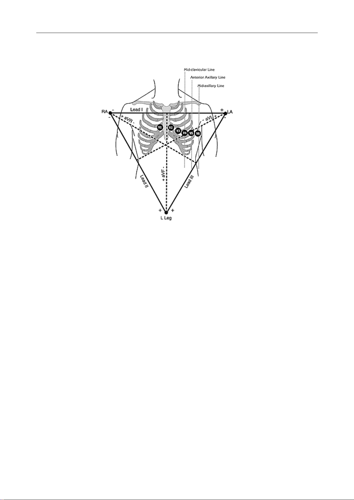
Each of the 12 leads represents a particular orientation in space, as indicated below (RA =
right arm; LA= left arm, LL = left leg):
Bipolar limb leads (frontal plane):
Lead I: RA (-) to LA (+) (Right Left, or lateral)
Lead II: RA (-) to LL(+) (Superior Inferior)
Lead III: LA (-) to LL(+) (Superior Inferior)
Augmented unipolar limb leads (frontal plane):
Lead aVR: RA (+) to [LA & LL](-) (Rightward)
Lead aVL:LA (+) to [RA & LL](-) (Leftward)
Lead aVF: LL(+) to [RA & LA] (-) (Inferior)
Unipolar (+) chest leads (horizontal plane):
Leads V1, V2, V3: (Posterior Anterior)
Leads V4, V5, V6:(RightLeft, or lateral)
Figure 3-2 Standardlimb leads
RA: right arm
LA: Left arm
LL: left Leg
V1: right 4th intercostal space
V2: left 4th intercostal space
V3: halfwaybetween V2and V4
V4: left 5th intercostal space, mid-clavicular line
SE-3 3-Channel Electrocardiograph Service Manual
-9-
V5: horizontal to V4, anterior axillaryline
V6: horizontal to V5, mid-axillaryline
Figure3-3Chest electrode of the standard limb leads
3.4 Hardware Design PrincipleDescription
The SE-3 electrocardiograph consists of the followingfunctional blocks:
1) Keyboard panel for user input/output;
2) Front_end module includingsignal acquisition, digital filter andthe amplifier;
3) ARM9 and peripheral module;
4) Thermal Printer module;
5) LCD displaymodule;
6) Power supplymodule.

SE-3 3-Channel Electrocardiograph Service Manual
-10-
Figure 3-4SE-3 machine blockdiagram
3.4.1 ECG Board description
Figure3-5ECG Board circuit blockdiagram

SE-3 3-Channel Electrocardiograph Service Manual
-11-
This module is a12-channel ECG signal samplingand processingmodule. Itcan realize the
amplification and pre-processing of patient ECG signal in everychannel, and the detection of
lead situations, as well as sendingdatato ARM9 MCU. This module is connected toARM9MCU
through UARTport.
The standard 12-lead electrocardiograph has 10 lead cables, including9lead signal input and 1
Right Foot electrode as the float ground. TheECG signals pass throughthe defibrillator
protection circuit, bufferingcircuit (U1~U3), and enter the difference amplifier circuit.And then
theycontinue to pass throughthepacemaker pulse restraining,high-passfilter,low-pass filter,
channel switch, secondlevel amplification, and are sent to the A/Dsamplingport of
MSP430F147.
Because the ECG system must meet the safetyrequirement of the photo-electricityisolation, the
serial signals will be sent to the photo-electricitycomponent.
3.4.2 Main control part description
The main control part includes ARM9 Board and Interface Circuit Board.
ARM9 Board consists of MCU S3C2410, SDRAM, NAND FLASH, NOR FLASH, LAN
controller, and CPLD etc. The main frequencyis 203MHz.
The interface Circuit Board consists of RS232 interface, LAN interface, USB interface, printer
interface, LCD interface,and keyboardinterface etc. Italso provides power supplyto the device.
Figure 3-6ARM9Board circuit blockdiagram
The system uses ARM9 (S3C2410) (U1) as the control MCU, and the peripheral equipments are
connected to the MCU ports. The MCU controls the peripheral equipments byseveral kinds of
methods. The system expands 64M external SDRAM (U6, U7), 64M FLASH (U2), LAN

SE-3 3-Channel Electrocardiograph Service Manual
-12-
Controller (U9) and CPLD (U8).
The Interface Circuit Board integrates all sockets for USB,Ethernet, Input/output, RS232 and
thermal printer.And themain control circuits include Paper Detection circuit (U18), Motor
Drivingcircuit (U16, U17), Thermal Recordingcircuit (U14, U15) and Heat Time Control circuit
(U19). And external analoginput is connected to MCU byU21.
The thermal recorder hasstep motor and transmission frame ofits own. And the paper detection
is carried out dependingon a photoelectric diode.
The keyboard usesfilmykeys,and the keyboard control component uses 3*4 matrixes, 12 keysin
total.
SE-3 (Configuration A) uses 192*64 LCD screenthat adopts 8bit businterface. The mainboard
of SE-3 uses 8 GPIO to simulate 8 bit buses to control the readingand writingof LCD screen.
SE-3 (Configuration B) uses 320*240 LCD screen that adopts standard FSTN interface. Because
ARM9 has the FSTN interface of its own, it can be drived directlyafter connected.
3.4.3 Power control part description
220VAC voltage passes linear transformer and is transformed into 20VAC voltage. One part is
provided to charge the battery, and another part passes DC/DC to provide +8Vfor thermal
prinhead, +5Vfor electric machine, +5Vfor core board and +5Vfor ECG board.

SE-3 3-Channel Electrocardiograph Service Manual
-13-
Chapter 4 Tests
4.1 System Tests
1. Unit appearance and assembly examinations
1) Clean appearance, firm assembly,no remainder in the unit when shakingit.
2) Keys feel well when pressing.
3) Labels are full and correct.
4) Standard configurations are full; Sockets are installed firmly.
5) Vibration test should be done before doingthe followingtests.
2. Switch on
After turned on, the electrocardiograph runs well and LCD screen displayswell.
4.2 Application System Tests
1. Equipment Requirement
Equipment Model
ECG emulator FLUKE MPS450
2. LCD screen tests
Observe if some characters are missing,orthere are bright spots and darkshadows on the LCD
screen. Observe if the waveforms, fonts and symbols displayed on the LCD screen are normal.
3. Lead off tests
Under AUTOmode, when pull out and insert thelead cables according to the sequence of the
lead cables inserted intothe ECG emulator,the electrocardiograph will accuratelyidentifythe
disconnection and connection of the correspondinglead cables.
When pull out several lead cables simultaneously,the electrocardiograph will give the hint
information of lead off circularly.
4. Keys tests
Press everykeyon the keyboard to test if theywork as the descriptions in the user manual.
5. Menu setup and store capability tests
Enter the More Setup interface of System Setup window,and set the Default as Yes, and then the

SE-3 3-Channel Electrocardiograph Service Manual
-14-
system will be shifted tothe main interface automatically.And then enter the corresponding
interfaces of the System Setup window to set the current time and change some menu options and
exit.
Turn offthe electrocardiograph, and turnon it fiveseconds later.Whentheelectrocardiographis
readyforexamination and recording,observe if the time displayed on the LCD screen is the
current time. And enter the correspondinginterfaces of the System Setup window to see if these
menus keep the changedoptions. Then restore these menus to the default values and turn offthe
electrocardiograph. Fiveseconds later,turn on the electrocardiograph again. When the
electrocardiograph is readyfor examination and recording,observe if the menus are still the
default options.
6. Heart Rate display tests
Set the heart rate output from the ECG emulator as different values, and the error of Heart Rate
values displayed on the LCD screen of electrocardiograph should be within ±1bpm. When the
heart rate output from the ECG emulator is 240bpm, the electrocardiograph will give the hint
information of Heart Rate exceedingthe limit and make an alarm sound.
7. Recording tests
1) Set the followingvalues:
The heart rate output of ECG emulator is 80bpm, the work mode of electrocardiograph is auto,
the speed is 25mm/s, theAC Filter is off, the Lowpass Filter is 150Hz and all the options in the
Record Settingmenu are on. Install the recordingpaper and press PRINT/STOPkeyto begin to
record.Examine whether the recordingcontent are integratedand consistent with the information
displayed on the LCD screen.
2) Make the ECG detector output the sine wavewith 2mVand 10Hz. Press PRINT/STOPkeyto
beginto record. Examine whether the recordingcontent are integratedand consistent with the
information displayed onthe LCD screen.The amplitude of ECG waveform of Lead Ishould not
be less than 25mm.
3) The ECG record includes: Date and time, ID, Name, Sex,Age, Sensitivity,Paper speed, filter,
Lead, 1mVcalibration mark, ECG waveform, Heart Rate etc. Meanwhile, before recordingECG
wave, 1mVCalibration mark and lead nameswill be recorded. Recorded characters and
waveforms are clear.
4) Open the casingof recorder and remove paper,the hint information of “Paper?”should be
displayed.Install the paper again and close thecasing of recorder,thehint information of
“Paper?”should disappear.

SE-3 3-Channel Electrocardiograph Service Manual
-15-
4.3 SafetyTests
1) Test the protection earth resistance accordingto IEC/EN 60601-1: Limit 0.1 ohm.
2) Test the earth leakagecurrent accordingto IEC/EN 60601-1: Limit: NC 500 uA, SFC 1000uA.
3) Test the patient leakage current accordingto IEC/EN 60601-1: Limit: 10 uA(CF).
4) Test the patient leakage current under single fault condition with mains voltageon theapplied
part accordingto IEC/EN 60601-1: Limit: 50uA(CF).
Other manuals for SE-3
1
Table of contents
Other EDAN INSTRUMENTS Medical Equipment manuals

EDAN INSTRUMENTS
EDAN INSTRUMENTS iM8s User manual

EDAN INSTRUMENTS
EDAN INSTRUMENTS SE-2003 Series User manual

EDAN INSTRUMENTS
EDAN INSTRUMENTS SE-12 Express Quick start guide

EDAN INSTRUMENTS
EDAN INSTRUMENTS VE-1010 User manual

EDAN INSTRUMENTS
EDAN INSTRUMENTS VE-100 User manual

EDAN INSTRUMENTS
EDAN INSTRUMENTS SE-3 User manual

EDAN INSTRUMENTS
EDAN INSTRUMENTS MT-206 User manual

EDAN INSTRUMENTS
EDAN INSTRUMENTS CADENCE User manual


