EDAN SD5 User manual


I
About this Manual
P/N: 01.54.456994
MPN: 01.54.456994011
Release Date: Oct. 2015
© Copyri ht EDAN INSTRUMENTS, INC. 2015. All ri hts reserved.
Statement
This manual will help you understand the operation and maintenance of the product better. It is
reminded that the product shall be used strictly complyin with this manual. User’s operation
failin to comply with this manual may result in malfunction or accident for which EDAN
INSTRUMENTS, INC. (hereinafter called EDAN) can not be held liable.
EDAN owns the copyri hts of this manual. Without prior written consent of EDAN, any
materials contained in this manual shall not be photocopied, reproduced or translated into other
lan ua es.
Materials protected by the copyri ht law, includin but not limited to confidential information
such as technical information and patent information are contained in this manual, the user shall
not disclose such information to any irrelevant third party.
The user shall understand that nothin in this manual rants him, expressly or implicitly, any
ri ht or license to use any of the intellectual properties of EDAN.
EDAN holds the ri hts to modify, update, and ultimately explain this manual.
Responsibility of the Manufacturer
EDAN only considers itself responsible for any effect on safety, reliability and performance of
the equipment if:
Assembly operations, extensions, re-adjustments, modifications or repairs are carried out by
persons authorized by EDAN, and
The electrical installation of the relevant room complies with national standards, and
The instrument is used in accordance with the instructions for use.
Upon request, EDAN may provide, with compensation, necessary circuit dia rams, and other
information to help qualified technician to maintain and repair some parts, which EDAN may
define as user serviceable.
Terms Used in this Manual
This uide is desi ned to ive key concepts on safety precautions.
WARNING
A WARNING label advises a ainst certain actions or situations that could result in personal

II
injury or death.
CAUTION
A CAUTION label advises a ainst actions or situations that could dama e equipment, produce
inaccurate data, or invalidate a procedure.
NOT
A NOTE provides useful information re ardin a function or a procedure.

III
Table of Contents
Chapter 1 Safety Guide ................................................................................................................. 1
1.1 Intended Use/Indications for Use ........................................................................................ 1
1.2 Safety Precautions ............................................................................................................... 1
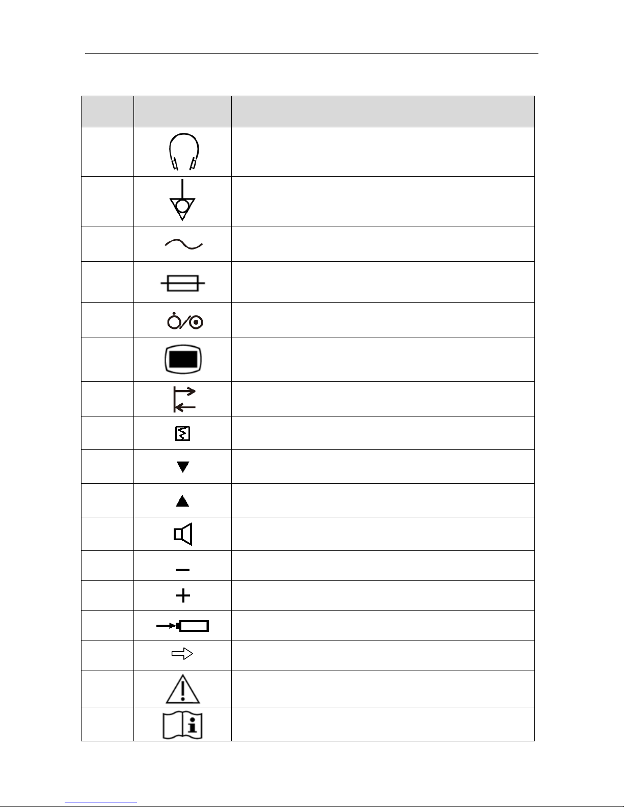
1.3 Symbols ............................................................................................................................... 4
Chapter 2 Introduction .................................................................................................................. 6
2.1 Main Unit ............................................................................................................................ 6
2.2 Probes .................................................................................................................................. 8
2.3 Control Keys ....................................................................................................................... 9
2.4 Indicators ........................................................................................................................... 10
2.5 LCD ................................................................................................................................... 11
Chapter Basic Operation .......................................................................................................... 1
3.1 Openin Packa e and Checkin ........................................................................................ 13
3.2 Usin Batteries .................................................................................................................. 13
3.2.1 Fittin Main Unit Battery ........................................................................................ 13
3.2.2 Fittin Wireless Probe Battery ................................................................................ 15
3.2.3 Char in Main Unit Battery.................................................................................... 16
3.2.4 Char in Wireless Probe Battery ............................................................................ 16
3.2.5 Care of Batteries ...................................................................................................... 17
3.3 Connectin the Power Cable ............................................................................................. 17
3.4 Usin Wired Probe ............................................................................................................ 17
3.4.1 Probe Socket ........................................................................................................... 17
3.4.2 Connectin and Disconnectin a Wired Probe ....................................................... 18
3.5 Switchin On ..................................................................................................................... 18
3.6 Switchin Off .................................................................................................................... 19
3.7 Usin Earphone ................................................................................................................. 20
3.8 Chan in Doppler Settin s ............................................................................................... 20
3.8.1 Switchin Backli ht On and Off ............................................................................. 20
3.8.2 Switchin Key Sound On and Off .......................................................................... 20
3.8.3 Settin Auto-Shut-Off Time ................................................................................... 21
3.8.4 Choosin Lan ua e ................................................................................................. 21
3.8.5 Settin Date and Time ............................................................................................. 21
3.8.6 Settin Date Format ................................................................................................ 21
3.9 Replacin Fuses ................................................................................................................ 22
Chapter 4 FHR Examining ......................................................................................................... 2
Chapter 5 Recording and Playing .............................................................................................. 25
Chapter 6 Maintenance and Cleaning ....................................................................................... 26

IV
6.1 Inspection .......................................................................................................................... 26
6.2 Maintenance ...................................................................................................................... 26
6.3 Cleanin ............................................................................................................................ 27
6.4 Disinfection ....................................................................................................................... 27
6.5 Sterilization ....................................................................................................................... 28
Chapter 7 Warranty and Service ............................................................................................... 29
7.1 Warranty ............................................................................................................................ 29
7.2 Contact information .......................................................................................................... 29
Chapter 8 Product Specifications ............................................................................................... 0
8.1 Environmental Specifications ........................................................................................... 30
8.2 Physical Specifications ..................................................................................................... 30
8.3 Performance Specifications ............................................................................................... 31
8.4 Battery Specifications ....................................................................................................... 32
8.5 Low Output Summary Table ............................................................................................. 33
Appendix 1 Ordering Information ............................................................................................. 4
Appendix 2 EMC Information .................................................................................................... 5
A2.1 Electroma netic Emissions ............................................................................................ 35
A2.2 Electroma netic Immunity ............................................................................................. 36
A2.3 Electroma netic Immunity ............................................................................................. 37
A2.4 Recommended Separation Distances ............................................................................. 38
Appendix Ultrasound Intensity and Safety ............................................................................ 9
A3.1 Ultrasound in Medicine .................................................................................................. 39
A3.2 Ultrasound Safety and the ALARA Principle ................................................................ 39
A3.3 Explanation of MI/TI ..................................................................................................... 39
A3.3.1 MI (Mechanical Index) ........................................................................................ 39
A3.3.2 TI (Thermal Index) ............................................................................................... 40
A3.3.3 Measurement Uncertainties .................................................................................. 40
A3.4 Prudent Use Statement ................................................................................................... 40
A3.5 References for Acoustic Output and Safety ................................................................... 41
A3.6 Probe Acoustic Output Parameters List ......................................................................... 41
Appendix 4 Overall Sensitivity ................................................................................................... 4
A4.1 Overall Sensitivity of SD5 (2MHz Wired Probe) .......................................................... 43
A4.2 Overall Sensitivity of SD5 (3MHz Wired Probe) .......................................................... 44
A4.3 Overall Sensitivity of SD6 (2MHz Wireless Probe) ...................................................... 45
A4.4 Overall Sensitivity of SD6 (3MHz Wireless Probe) ...................................................... 46

SD5/SD6 Ultrasonic TableTop Doppler User Manual Safety Guide
- 1 -
Chapter 1 Safety Guide
NOT :
Familiarize yourself with this user manual before attemptin to operate the Doppler.
Follow the operation and maintenance instructions to ensure proper use of it.
1.1 Intended Use/Indications for Use
The SD5 Ultrasonic TableTop Doppler (hereinafter called “SD5”) and SD6 Ultrasonic TableTop
Doppler (hereinafter called “SD6”) are intended to be used by health care professionals includin
re istered nurses, practical nurses, midwives, ultrasound technicians, and physician assistants, by
prescription from licensed physicians in hospitals, clinics and private offices.
The 2 MHz and/or 3 MHz obstetrical probes are indicated for the detection of fetal heart rate
from early estation thru delivery and as a eneral indication of fetal well bein . They can also be
used to verify fetal heart viability.
1.2 Safety Precautions
WARNING and CAUTION messa es must be observed. To avoid the possibility of injury,
observe the followin precautions durin the operation of the device.
WARNING
1 SD5/SD6 Ultrasonic TableTop Doppler is a tool to aid healthcare professionals and
should not be used in place of normal fetal monitorin . It is not intended for
treatment.
2 This device is not explosion-proof and can not be used in the presence of flammable
anaesthetics.
3 SHOCK HAZARD – In order to protect the patient and the operator, the device case
should be rounded. The power receptacle must be a three-slot rounded outlet.
4 SHOCK HAZARD – Do not attempt to connect or disconnect a power cord with wet
hands. Make sure that your hands are clean and dry before touchin a power cord.
5 Accessory equipment connected to the analo and di ital interfaces must be
certified accordin to the respective IEC/EN standards (e. . IEC/EN 60950 for data
processin equipment and IEC/EN 60601-1 for medical equipment). Furthermore all
confi urations shall comply with the valid version of the system standard IEC/EN
60601-1. Anybody who connects additional equipment to the si nal input connector
or si nal output connector to confi ure a medical system must ensure that the
system complies with the requirements of the valid version of the system standard
IEC/EN 60601-1. If in doubt, consult our technical service department or your local
distributor.
6 Exposure to ultrasound should be kept as low as reasonably achievable.

SD5/SD6 Ultrasonic TableTop Doppler User Manual Safety Guide
- 2 -
WARNING
7 Do not touch the si nal input/output connector and the patient simultaneously.
8 Do not apply this device and other ultrasonic equipment simultaneously on the same
patient, in case of possible hazard caused by leaka e current superposition.
9 Do not apply this device simultaneously with other PATIENT-connected equipment,
such as, a cardiac pacemaker or other electrical stimulators, on the same patient.
10 The device is not protected a ainst defibrillation.
11 Do not use the device with HF sur ical equipment.
12 Only use the probes provided by the manufacturer.
13 Before usin the battery, make sure to read the user manual and safety precautions
thorou hly.
14 Do not heat or throw the battery into fire as this may cause explosion.
15 Do not solder the leadin wire and the battery terminal directly.
16 Do not destroy the battery: Do not pierce the battery with a sharp object such as a
needle; do not hit with a hammer, step on or throw or drop to cause stron shock; do
not disassemble or modify the battery.
17 The battery should be char ed, used or stored away from the static electricity.
18 Do not mix the battery with metal objects to avoid short-circuit.
19 The battery should be char ed at least once a month to prevent overdischar e.
20 Replacement or char in of the battery shall be done at least 1.5 meters away from
patients.
21 The device shall only be used when the battery cover is closed.
22 If the device is not used for a lon time, please remove the battery and store it as
required.
23 If the liquid leak from the battery spills onto your skin or clothes, wash well with fresh
water immediately.
24 If the liquid leak from the battery ets into eyes, do not rub the eyes. Wash them
well with clean water and see a doctor immediately.
25 Stop usin the battery if abnormal heat, odor, discoloration, deformation or any other
abnormal condition is detected durin use, char e, or stora e. Please dispose it
accordin to the local re ulations.
26 Do not immerse, throw, or wet the battery in water/seawater.
27 Do not connect any equipment or accessories that are not approved by the
manufacturer or that are not IEC 60601-1 approved to the device. The operation or
use of non-approved equipment or accessories with the device is not tested or
supported, and device operation and safety are not uaranteed.

SD5/SD6 Ultrasonic TableTop Doppler User Manual Safety Guide
- 3 -
WARNING
28 Usin accessories other than those specified by the manufacturer may result in
increased electroma netic emissions or decreased electroma netic immunity of the
device.
29 The appliance coupler or mains plu is used as isolation means from supply mains.
Position the device in a location where the operator can easily access the
disconnection device.
30 The device should not be used adjacent to or stacked with other equipment and that
if adjacent or stacked use is necessary, the device should be observed to verify
normal operation in the confi uration in which it will be used.
31 The medical electrical equipment needs to be installed and put into service
accordin to the EMC Information provided in this user manual.
32 Portable and mobile RF communications equipment can affect medical electrical
equipment, refer to section A2.4 Recommended Separation Distances.
33 Do not service or maintain the device or any accessory which is in use with a
patient.
CAUTION
1 Federal (U.S.) law restricts this device to sale by or on the order of a physician.
2 Refer servicin to qualified service personnel.
3 The main unit is desi ned for continuous operation and is ‘ordinary’. It is not
waterproof; do not immerse it in any liquid (i.e. not drip or splash-proof).
4 Keep the device clean. Avoid vibration.
5 Do not sterilize the Doppler with autoclave or as.
6 lectromagnetic Interference
–
Ensure that the environment in which the device is
operated is not subject to any source of stron electroma netic emissions, such as
radio transmitters, mobile telephones, etc.
7 Check that the equipment does not have visible evidence of dama e that may affect
personnel’s safety or examinin capability before use. If dama e is detected,
replacement is recommended.
8 The device and accessories are to be disposed of accordin to local re ulations
after their useful lives. Alternatively, they can be returned to the dealer or the
manufacturer for recyclin or proper disposal. Batteries are hazardous waste. Do
NOT dispose them to ether with house-hold arba e. At the end of their life hand
the batteries over to the applicable collection points for the recyclin of waste
batteries. For more detailed information about recyclin of this product or battery,
please contact your local Civic Office, or the shop where you purchased the product.

SD5/SD6 Ultrasonic TableTop Doppler User Manual Safety Guide
- 4 -
1.3 Symbols
No. Symbol Definition
1
Headphones
2
Equipotential roundin
3
Alternatin Current
4
Fuse
5 ON/OFF switch
6
Menu
7
Recordin and play-back
8 Print control
9 Move the cursor downwards
10 Move the cursor upwards
11 Speaker
12 Decrease
13 Increase
14 Char e battery
15 Push ri ht
16
Caution
17
Operatin instructions

SD5/SD6 Ultrasonic TableTop Doppler User Manual Safety Guide
- 5 -
18
TYPE BF APPLIED PART
19 CE markin
20
Disposal method
21 IPX4
The device is protected a ainst splashin water. Water splashed
a ainst the enclosure from any direction shall have no harmful
effects.
22 Part Number
23 SERIAL NUMBER
24
Date of manufacture
25
MANUFACTURER
26
AUTHORISED REPRESENTATIVE IN THE EUROPEAN
COMMUNITY
27
General symbol for recovery/recyclable
28
Caution: Federal (U.S.) law restricts this device to sale by or
on the order of a physician.
29
Refer to User Manual
(Back round: Blue; Symbol: White)
30
Non-ionizin electroma netic radiation
31* FCC ID:
SMQSD6PEDAN
Federal Communications Commission: FCC ID:
SMQSD6PEDAN
32* FCC ID:
SMQSD6MEDAN
Federal Communications Commission: FCC ID:
SMQSD6MEDAN
NOT :
1 The user manual is printed in black and white.
2 * Applicable to SD6 only.

SD5/SD6 Ultrasonic TableTop Doppler User Manual Introduction
- 6 -
Chapter 2 Introduction
NOT :
The pictures and interfaces in this manual are for reference only.
2.1 Main Unit
SD5:
SD6:
Fi ure 2-1 Overview
Fi ure 2-2 Top View of the Main Unit
1 Probe
2 Probe Cable
3 Main Unit
4 LCD
5 Speakers
6 Probe Socket
8
9
10
7 Probe Holder
8 Handle
9 Probe Sensor Socket
10 Main Unit Control Keys
1
2
3
4
5
6
5
3
4
5
5
7
1

SD5/SD6 Ultrasonic TableTop Doppler User Manual Introduction
- 7 -
WARNING
Please do not touch the probe sensor socket and the patient simultaneously.
Fi ure 2-3 Main Unit Control Keys
Fi ure 2-4 Back View of the Main Unit
Fi ure 2-5 Ri ht View of the Main Unit
NOT :
The main unit is not waterproof. Do not immerse it in any type of liquid.
18
17
16
20
19
16 Fuses
17 Power Socket
18 Equipotential Groundin
Terminal
19 Main Unit Label
20 Earphone Socket
21 Battery Compartment
21
11 12 13 14 15
11 Main Unit Indicator
12 On/OFF Key
13 Setup Key / Confirm Key
14 Up Key /
Record/Play Control Key
15 Down Key /
Print Control Key

SD5/SD6 Ultrasonic TableTop Doppler User Manual Introduction
- 8 -
2.2 Probes
WARNING
Do not touch the char e sockets of the Doppler probe and the patient simultaneously.
CAUTION
1. Do not immerse the probe (and the probe cable) in any liquid.
2. Do not stretch the probe cable for more than three meters.
Wireless Probe:
Wired Probe:
Fi ure 2-6 Top View of the Probe
Fi ure 2-7 Probe Control Keys
Fi ure 2-8 Bottom View of the Probe
1 Acoustic Face
2 Probe Control Keys
3 Probe Socket
4 Probe Cable
2
1
5 6 7 8
9 Probe Type Label
10 Probe Battery Compartment
11 Probe Char e Socket
9 10 11
4
3
1
2
5 Volume Decreasin Key
6 Volume Increasin Key
7 Power Key (only available
on wireless probe)
8 Probe Indicator

SD5/SD6 Ultrasonic TableTop Doppler User Manual Introduction
- 9 -
Description:
The Doppler supports 2 MHz and 3 MHz probes supplied by the manufacturer. The probe
nominal frequency is disclosed on the probe type label.
Probes of SD5 are wired, while probes of SD6 are wireless.
WARNING
SD6 complies with Part 15 of the FCC Rules. Operation is subject to the followin two
conditions:
1) this device may not cause harmful interference, and
2) this device must accept any interference received, includin interference that may
cause undesired operation.
NOT :
1. This equipment (SD6) has been tested and found to comply with the limits for a
Class B di ital device, pursuant to part 15 of the FCC Rules. These limits are
desi ned to provide reasonable protection a ainst harmful interference in a
residential installation. This equipment enerates, uses and can radiate radio
frequency ener y and, if not installed and used in accordance with the instructions,
may cause harmful interference to radio communications. However, there is no
uarantee that interference will not occur in a particular installation. If this equipment
does cause harmful interference to radio or television reception, which can be
determined by turnin the equipment off and on, the user is encoura ed to try to
correct the interference by one or more of the followin measures:
- Reorient or relocate the receivin antenna.
- Increase the separation between the equipment and receiver.
- Connect the equipment into an outlet on a circuit different from that to which the
receiver is connected.
- Consult the dealer or an experienced radio/TV technician for help.
2.
Any chan es or modifications to this unit not expressly approved by the party
responsible for compliance could void the user's authority to operate the equipment.
2.3 Control Keys
Control keys are provided to switch on or off the device, perform the functions and chan e the
settin s.
A beep sound will be heard when you press a key of the main unit. Or you can switch off the
sound. Refer to section 3.8.2 Switching the Key Sound On and Off for operation procedures.
(1) Power Key

SD5/SD6 Ultrasonic TableTop Doppler User Manual Introduction
- 10 -
Function: Switch on/off the main unit or switch on the probe. Note that if the probe fails to
connect the main unit in two minutes, it will power off automatically.
(2) Up Key / Record/Play Control Key
Function: Move the cursor upwards to the previous item (in the settin mode).
Recordin and playin control (in the real-time examinin mode).
(3) Down Key / Print Control Key
Function: Move the cursor downwards to the next item (in the settin mode).
Printin control (reserved).
(4) Setup Key / Confirm Key
Function: Enter setup menu (in the real-time examinin mode).
Confirm selection (in the settin mode).
(5) Volume Control Keys
Function: Decrease the FHR volume ( ). Increase the FHR volume ( ).
2.4 Indicators
(1) Main unit indicator
The indicator of the main unit indicates the connection status of the main unit and AC power:
The indicator li hts up in reen – the AC power is connected.
The indicator flashes in reen – the main unit is char in the main unit battery.
The indicator oes off – the AC power is not connected.
(2) Probe indicator
The indicator of the probe indicates the status of the probe:
The indicator li hts up in reen – the probe is switched on.
The indicator flashes in yellow when the volume control key is pressed – the volume has
been decreased/increased to its minimum/maximum.
For SD6, the indicator li hts up continuously in yellow – the probe battery is low; the
indicator flashes in reen – the probe battery is bein char ed.

SD5/SD6 Ultrasonic TableTop Doppler User Manual Introduction
- 11 -
2.5 LCD
The Doppler has four modes: examinin mode, recordin mode, playin mode and settin mode.
In the former three modes, the LCD displays as follows:
Item
Description
1 Battery Indicator
The battery is installed and the battery ener y is full.
The main unit battery is low.
The main unit battery is not installed.
2 Recordin Indicator: The Doppler is recordin fetal heart sound. (Only in the recordin
mode)
3 Playin Indicator: The Doppler is playin the recorded fetal heart sound. (Only in the
playin mode)
4 AC Indicator AC power is connected.
5
Bluetooth Indicator
(Only available with
SD6)
The wireless probe is switched on and its communication
with the main unit is normal.
The wireless probe is switched off or its communication with
the main unit failed.
Probe Indicator
(Only available with
SD5)
The wired probe is well connected.
The wired probe is not connected.
6 Fetal heart si nal intensity indicator
7 FHR numeric measurement value
8, 9 Date and Time
10 Heart Beat Indicator: When fetal heart si nal is received, the heart shape flashes to
indicate the FHR refreshin frequency.
11 Volume Indicator
1
2
3
8
9
10
11
5
4
6 7

SD5/SD6 Ultrasonic TableTop Doppler User Manual Introduction
- 12 -
In the settin mode, the LCD displays as the ri ht fi ure
shows.
The rectan ular mark that moves up and down is called the
“cursor”. Press the Up key or the Down key to move it
back or forth.
The LCD displays the battery char in icon when the main
unit is shut off and char in . Durin the char in process,
the battery char in icon chan es as the battery level
increases.

SD5/SD6 Ultrasonic TableTop Doppler User Manual Basic Operation
- 13 -
Chapter 3 Basic Operation
3.1 Opening Package and Checking
Open the packa e; take out the Doppler and accessories carefully. Place them on a flat, clean
surface.
Keep the packa e for possible future transportation or stora e. Check the components accordin
to the packin list.
Check for any mechanical dama e.
Check all the cables and accessories.
If there is any problem, contact us or your local distributor immediately.
3.2 Using Batteries
CAUTION
The fittin of the batteries should be carried out by the manufacturer's authorized
personnel.
3.2.1 Fittin Main Unit Battery
The main unit is powered either by alternatin current or a Ni-MH battery.
It is recommended to power the main unit solo by a battery durin operation. Therefore, char e
the battery fully before use to ensure enou h power. Connectin to mains power supply will
char e the battery no matter if the main unit is on or off.
WARNING
Switch off the Doppler and remove the power cord before fittin the main unit battery.
To fit the battery for the main unit:
1 Follow the arrow direction to open the battery compartment cover. The battery connectin
cable & connector and the metal insert show up.

SD5/SD6 Ultrasonic TableTop Doppler User Manual Basic Operation
- 14 -
2 Tilt the battery sideways and put its bottom left corner into the battery compartment from the
left end of the compartment to the ri ht. Make sure connector ① stays out of the compartment.
3 Keep pushin the battery into the compartment until the metal insert sprin s back to lock the
battery.
Battery Connectin
Cable & Connector
Metal Insert
Battery Connector ①
Battery Connector ②

SD5/SD6 Ultrasonic TableTop Doppler User Manual Basic Operation
- 15 -
4 Connect the two connectors (①&②) and then put them into the compartment.
5 Close the battery compartment cover.
3.2.2 Fittin Wireless Probe Battery
The wireless probe is powered by a lithium battery.
To fit the battery for the probe:
1 Remove the screw on the battery compartment cover with a screw driver and then take the
cover away with your hand.
Other manuals for SD5
1
This manual suits for next models
1
Table of contents
Other EDAN Medical Equipment manuals