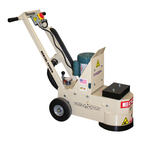
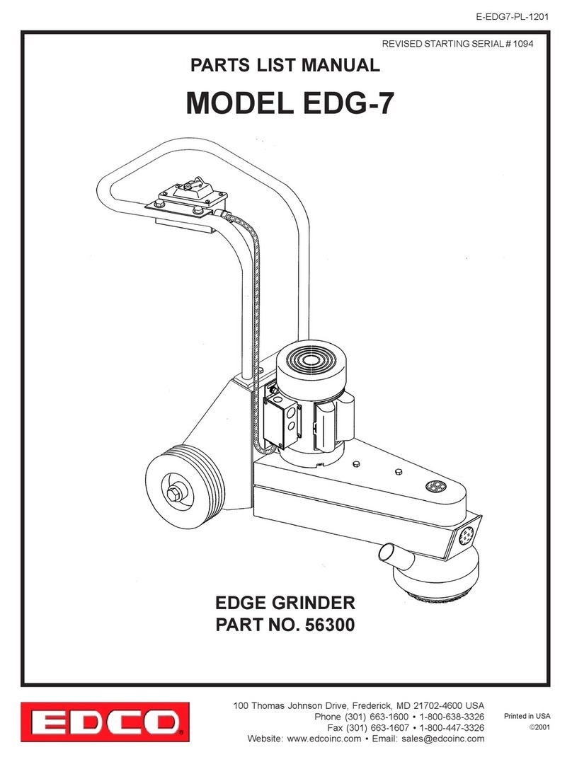
Edco 2-EC User manual

Printed in USA
©2012 TVW
Page 2
E-SEC,2EC,2GC-P,4GC-I-0512
100 Thomas Johnson Drive, Frederick, MD 21702-4600 USA
Phone (301) 663-1600 • 1-800-638-3326
Fax (301) 663-1607 • 1-800-447-3326
Website: www.contrxsystems.com
Email: [email protected]
READ AND UNDERSTAND THE OPERATORS INSTRUCTION MANUAL THOROUGHLY
BEFORE ATTEMPTING TO OPERATE THIS EQUIPMENT.
Death or serious injury could occur if this machine is used improperly.
Extreme care must be taken when operating electric
modelswithwaterpresent: Ensurepowercordisprop-
erlygrounded,isattachedtoaGround-Fault-Interrupter
(GFI) outlet, and is undamaged.
•Check all electrical cables - be sure connections are tight and
cable is continuous and in good condition. Be sure cable is
correctly rated for both the operating current and voltage of
this equipment.
•Improperconnection oftheequipment-grounding conductorcan
result in a risk of electric shock. Check with qualified electri-
cian or service person if there is any doubt as to whether the
outlet is properly grounded. Adhere to all local codes and
ordinances.
•NOTE: In the event of a malfunction or breakdown, grounding
provides a path of least resistance for the electric current to
dissipate. The motor is equipped with a grounded plug and
must be connected to an outlet that is properly installed and
properly grounded. DO NOT modify the plug provided on the
motor. If the plug does not fit the outlet have a qualified electri-
cian install the proper receptacle.
•Switch motor OFF before disconnecting power.
•Engine exhaust from this product contains
chemicals known to the State of California to
cause cancer, birth defects or other reproduc-
tive harm.
•Gasoline is extremely flammable and poisonous.
It should only be dispensed in well ventilated areas,
and with a cool engine.
•Small gasoline engines produce high concentra-
tions of carbon monoxide (CO) example: a 5 HP 4 cycle
engine operation in an enclosed 100,000 cu. ft. area with
only one change of air per hour is capable of providing
deadly concentrations of CO in less than fifteen minutes.
Five changes of air in the same area will produce noxious
fumes in less than 30 minutes. Gasoline or propane pow-
ered equipment should not be used in enclosed or partially
enclosed areas. Symptoms of CO poisoning include, head-
ache, nausea, weakness, dizziness, visual problems and
loss of consciousness. If symptoms occur - get into fresh
air and seek medical attention immediately.
SAFETY
MESSAGES SAFETY MESSAGES
Indicates an imminent hazard which, if not
avoided, will result in death or serious injury.
Indicates an imminent hazard which, if not
avoided, can result in death or serious injury.
Indicates hazards which, if not avoided, could
result in serious injury and or damage to the
equipment.
•Safety Instructions are proceeded by a graphic alert symbol
of DANGER, WARNING, or CAUTION.
ELECTRICAL POWERED EQUIPMENT
GASOLINE/PROPANE POWERED EQUIPMENT
•Equipment should only be operated by trained personnel in
good physical condition and mental health (not fatigued). The
operator and maintenance personnel must be physically able
to handle the bulk weight and power of this equipment.
•This is a one person tool. Maintain a safe operating distance
to other personnel. It is the operators’responsibility to keep
other people (workers, pedestrians, bystanders, etc.) away
during operation. Block off the work area in all directions with
roping, safety netting, etc. for a safe distance. Failure to do so
may result in others being injured by flying debris or exposing
them to harmful dust and noise.
•This equipment is intended for commercial use only.
•For the operator’s safety and the safety of others, always keep
all guards in place during operation.
•Never let equipment run unattended.
•Personal Protection Equipment and proper safety attire must
be worn when operating this machinery. The operator must
wear approved safety equipment appropriate for the job such
as hard hat and safety shoes when conditions require. Hear-
ing protection MUST be used (operational noise levels of this
equipment may exceed 90db). Eye protection MUST be worn
at all times.
Keep body parts and loose clothing away from moving
parts. Failure to do so could result in dismemberment
or death.
•Do not modify the machine.
•Stopmotor/enginewhenadjusting or servicing this equipment.
Maintain a safe operating distance from flammable
materials. Sparksfrom the cutting-action of this machine
can ignite flammable materials or vapors.
GENERAL INSTRUCTIONS
DUST WARNING
Some dust created by power sanding, sawing,
grinding, drilling, and other construction activi-
tiescontainschemicalsknownto cause cancer,
birthdefects,or other reproductive harm. Some
examples of these chemicals are:
•Lead from lead-based paints, and
•Crystalline silica from bricks and concrete and other
masonry products.
Your risk of exposure to these chemicals varies depending
on how often you do this type of work. To reduce your risk:
workin a wellventilatedarea, use adustcontrolsystem, such
as an industrial-style vacuum, and wear approved personal
safetyequipment, such as a dust/particlerespiratordesigned
to filter out microscopic particles.
•Donotdisconnect power by pulling cord. To disconnect,grasp
the plug, not the cord.
•Unplug power cord at the machine when not in use and before
servicing.

Printed in USA
©2012 TVW
Page 4
E-SEC,2EC,2GC-P,4GC-I-0512
100 Thomas Johnson Drive, Frederick, MD 21702-4600 USA
Phone (301) 663-1600 • 1-800-638-3326
Fax (301) 663-1607 • 1-800-447-3326
Website: www.contrxsystems.com
Email: [email protected]
Operating Controls
Please Note:
Controls shown are for the model indicated.
The location of these controls may vary on the
different models.
Due to improvements and changes in the
equipment, the illustration shown may vary
from the actual machine.
Figure 2
Electric Powered
(SEC)
Electric Motor
Power
On/Off
Switch
Accessory
Box
Vibration
Dampening
Handles
Dust Skirt
Water Hook-up
and on/off valve
back of machine
Multi-Vac
Port
Lifting
Bail
Grease
point
Figure 3
Electric Powered
(2EC)
Electric Motor
Power
On/Off
Switch
Electrical
Plug
Vibration
Dampening
Handles
Dust Skirt
Water Hook-up
and on/off valve
Multi-Vac
Port
Figure 5
Propane Powered
(4GC)
Throttle
Depth
Control
Vibration
Dampening
Handles
Dust Skirt
Muffler
Electric
Starter
Propane
Tank
NOTE: Operating controls are the same for the gasoline
and propane models.
Multi-Vac
Port
Figure 4
Gasoline Powered
(2GC)
Dust Skirt
Engine Stop Switch Cushioned
hand grips
Choke
Control
hidden
Throttle
Recoil
Starter Grip
NOTE: Operating controls are the same for the gasoline
and propane models.
Water Hook-up
and on/off valve Multi-Vac
Port

Printed in USA
©2012 TVW
Page 6
E-SEC,2EC,2GC-P,4GC-I-0512
100 Thomas Johnson Drive, Frederick, MD 21702-4600 USA
Phone (301) 663-1600 • 1-800-638-3326
Fax (301) 663-1607 • 1-800-447-3326
Website: www.contrxsystems.com
Email: [email protected]
• Read and understand all operating instructions before operating this equipment. Death
or serious injury can result if this machine is used improperly.
• Concrete grinders are designed to be used to grind flat horizontal concrete slabs using EDCO
approved accessories.
• The machines are equipped with gasoline/propane engines and electric motors.
• They are designed to be controlled by a single operator from a position at the rear of the machine.
• When operating equipment maintain a safe distance from other personnel in the area.
Be sure to read the complete instructions supplied with your machine.
IMPORTANT: Perform Pre-Start Check.
• Visually inspect the equipment for wear or damage.
• Be sure all guards are in place and functioning properly. Do not operate unless all guards are in place and secure.
• Perform all daily maintenance.
• Check to be sure water tubes are functioning properly if performing wet-grinding operations.
• Inspect accessories - Be sure the correct accessory is installed properly on the machine, mounting arrangement and
its intended use.
• Check accessories for damage (see figure 6, below), the type of wear or damage will vary with the type if acces-
sory.
• Inspect work area to determine the presence and location of deck inserts, pipes, columns and objects protruding from
the slab surface so that they may be avoided during the grinding operation.
• FOR WET GRINDING: Attach the water supply. A flow rate of approximately 1/2 gallon per minute is recommend-
ed.
Operating Instructions
Figure 6
EXAMPLE OF SEVERELY WORN
DYMA-SERT EXAMPLE OF AN EVENLY WORN
DYMA-SERT
The above in an example of a DYMA-SERT that has
not been rotated after every four hours of use. To get
maximum life out of a DYMA-SERT they should be
rotated 180º every four hours of use.
The above in an example of a DYMA-SERT that has
been rotated after every four hours of use, as you
can see the wear is even across all segments.

Printed in USA
TVW ©2012
Page 7
E-SEC,2EC,2GC-P,4GC-I-0512
100 Thomas Johnson Drive, Frederick, MD 21702-4600 USA
Phone (301) 663-1600 • 1-800-638-3326
Fax (301) 663-1607 • 1-800-447-3326
Website: www.contrxsystems.com
Email: [email protected]
Operating Instructions
• BEFORE STARTING THE ENGINE: Raise the front of the machine clear of the working surface.
• START ENGINE AND ALLOW IT TO REACH OPERATING SPEED. Position the grinder at the starting point.
Bring the engine to full speed. Lower the machine onto the slab surface. Use a slow sweeping motion from left right
and back continously, and do not force the machine into the work, the engine or motor should not strain
when grinding.
• WHEN WET GRINDING: Water is required. Attach the water hose to the water hook-up valve. Use the valve to
control the flow of water.
• FOR DRY GRINDING: Provide a respirator and dust control system.
• FOR GASOLINE MODELS: Put the engine stop switch in the “RUN” position. Consult the engine manufac-
turers operating instructions and follow the directions for starting and breaking in the engine.
• TO STOP THE MACHINE: Stop forward motion. On gasoline models push the throttle to idle. Turn ignition
or power switch off and let the engine come to a complete stop. Turn off the water supply.
• WHEN MANEUVERING THE GRINDER: Tilt grinder back enough so it does not strike the slab surface. Damage to
accessories may occur with inadvertent contact with the slab.
• DO NOT FORCE GRINDER WHILE GRINDING.
• IF THE POWER SOURCE FAILS: Raise the grinder off of the floor. Disconnect the power source (i.e. the
spark plug wire on a gasoline engine). Inspect the accessories for damage. Replace damaged (or questionable)
accessories immediately.
• WHEN TRANSPORTING THE GRINDER: Disconnect the power source before lifting or removing any guard.
See the directions for changing accessories on page 9.
• WHEN HOISTING OR LIFTING A GRINDER : Always inspect frame and attaching hardware for damage
before lifting. Use proper safe hoisting and lifting techniques and hardware.
Grinding/cutting/drilling of masonry, concrete, metal and other materials can generate dust, mists and fumes containing
chemicals known to cause serious or fatal injury or illness, such as respiratory disease, cancer, birth defects or other
reproductive harm. If you are unfamiliar with the risks associated with the particular process and/or material being
cut or the composition of the tool being used, review the material safety data sheets and/or consult your employer,
the manufacturers/suppliers, governmental agencies such as OSHA and NIOSH and other sources on hazardous
materials. California and some other authorities, for instance, have published lists of substances known to cause
cancer, reproductive toxicity, or other harmful effects.
Control dust, mist and fumes at the source where possible. In this regard use good work practices and follow the recom-
mendations of the manufacturers/suppliers, OSHA/NIOSH, and occupational and trade associations. Water should
beused for dustsuppression when wetgrinding/cutting/drilling is feasible. Whenthe hazards frominhalationof dust,
mists and fumes cannot be eliminated, the operator and any bystanders should always wear a respirator approved
by NIOSH/MSHA for the material being used.
Grinding/cutting/drilling of masonry, concrete and other materials with silica in their composition may give off dust or
mists containing crystalline silica. Silica is a basic component of sand, quartz, brick clay, granite and numerous
other minerals and rocks. Repeated and/or substantial inhalation of airborne crystalline silica can cause serious or
fatalrespiratorydiseases, including silicosis. Inaddition, California and someother authorities have listedrespirable
crystalline silica as a substance known to cause cancer. When grinding/cutting/drilling such materials, always follow
the respiratory precautions mentioned above.
SMI Dust and Silica Warning

Printed in USA
TVW ©2012
Page 13
E-SEC,2EC,2GC-P,4GC-I-0512
100 Thomas Johnson Drive, Frederick, MD 21702-4600 USA
Phone (301) 663-1600 • 1-800-638-3326
Fax (301) 663-1607 • 1-800-447-3326
Website: www.contrxsystems.com
Email: [email protected]
PROCEDURE FOR LUBRICATING FLANGE BEARINGS
To grease the flange bearings attach the grease gun to the grease fittings and give only two (2) pumps on the grease gun
every 50 hours of use. If excessive over lubrication is done grease will leak onto the work surface causing possible dam-
age and wasted cleanup time.
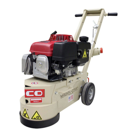
If using a vacuum for dust control attach it to the vacuum port at the rear of the machine except for the SEC and 4GC
which is on the handle as pictured above, securing it with clamps. The ports are shown in the photos above.
PROCEDURE FOR ATTACHING A VACUUM
The procedure is the same for two or four disc machines. The hood has to be removed to access the grease points on the
flange bearings. The single disc grinder is lubricated through the access hole on the front of the machine and under the belt
cover. The grease points are circled in the photos above. There are duplicate grease fittings on the underside of the 2EC,
2GC and the 4GC models. The skirts will have to be removed to access the grease points.
SEC 2GC 4GC
Inspection
hole Inspection
hole
Gear
case Gear
case
Vac
Port Multi-Vac
Port
Multi-Vac
Port
hidden
Other manuals for 2-EC
2
This manual suits for next models
3
Table of contents
Other Edco Grinder manuals

Edco
Edco MAGNA-TRAP TMC-7 Assembly instructions

Edco
Edco SEC-HD User manual

Edco
Edco EDG-7 Datasheet

Edco
Edco TG-10 Assembly instructions

Edco
Edco MAGNA-TRAP TMC-7 Assembly instructions

Edco
Edco Magna-Trap 2D-HDG Assembly instructions

Edco
Edco MAGNA-TRAP TMC-7 Assembly instructions

Edco
Edco 2ECEGNG User manual

Edco
Edco SECNG-1.5L User manual

Edco
Edco TG-10 Assembly instructions