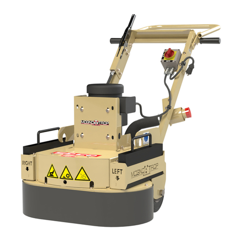
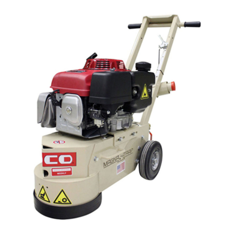
Edco Magna-Trap 2D-HDG Assembly instructions

2DHD-I-0515
Printed in USA
©2015
Page 1
EQUIPMENT DEVELOPMENT CO., INC.
Operators Instruction Manual
2D-HD
ELECTRIC
PROPANE
To order go to Discount-Equipment.com

We sell worldwide for the brands: Genie, Terex, JLG, MultiQuip, Mikasa, Essick, Whiteman,
Mayco, Toro Stone, Diamond Products, Generac Magnum, Airman, Haulotte, Barreto, Power
Blanket, Nifty Lift, Atlas Copco, Chicago Pneumatic, Allmand, Miller Curber, Skyjack, Lull,
Skytrak, Tsurumi, Husquvarna Target, Stow, Wacker, Sakai, Mi-T-M, Sullair, Basic, Dynapac,
MBW, Weber, Bartell, Bennar Newman, Haulotte, Ditch Runner, Menegotti, Morrison, Contec,
Buddy, Crown, Edco, Wyco, Bomag, Laymor, EZ Trench, Bil-Jax, F.S. Curtis, Gehl Pavers, Heli,
Honda, ICS/PowerGrit, IHI, Partner, Imer, Clipper, MMD, Koshin, Rice, CH&E, General Equip-
ment ,Amida, Coleman, NAC, Gradall, Square Shooter, Kent, Stanley, Tamco, Toku, Hatz,
Kohler, Robin, Wisconsin, Northrock, Oztec, Toker TK, Rol-Air, APT, Wylie, Ingersoll Rand /
Doosan, Innovatech, Con X, Ammann, Mecalac, Makinex, Smith Surface Prep,Small Line,
Wanco, Yanmar
Discount-Equipment.com is your online resource for
commercial and industrial quality parts and equipment sales.
561-964-4949
visit us on line @ www.discount-equipment.com
TO PURCHASE THIS PRODUCT PLEASE CONTACT US
Select an option below to find your Equipment
Equipment Financing and
Extended Warranties Available

2DHD-I-0515
Printed in USA
©2015
Page 2
READ AND UNDERSTAND THE OPERATORS INSTRUCTION MANUAL THOROUGHLY
BEFORE ATTEMPTING TO OPERATE THIS EQUIPMENT.
Death or serious injury could occur if this machine is used improperly.
Extreme care must be taken when operating electric
models with water present: Ensure power cord is prop-
erly grounded, is attached to a Ground-Fault-Interrupter
(GFI) outlet, and is undamaged.
•Check all electrical cables - be sure connections are tight and
cable is continuous and in good condition. Be sure cable is
correctly rated for both the operating current and voltage of
this equipment.
•Improper connection of the equipment-grounding conductor can
result in a risk of electric shock. Check with qualied electri-
cian or service person if there is any doubt as to whether the
outlet is properly grounded. Adhere to all local codes and
ordinances.
•NOTE: In the event of a malfunction or breakdown, grounding
provides a path of least resistance for the electric current to
dissipate. The motor is equipped with a grounded plug and
must be connected to an outlet that is properly installed and
properly grounded. DO NOT modify the plug provided on the
motor. If the plug does not t the outlet have a qualied electri-
cian install the proper receptacle.
•Switch motor OFF before disconnecting power.
•Engine exhaust from this product contains
chemicals known to the State of California to
cause cancer, birth defects or other reproduc-
tive harm.
•Gasoline is extremely ammable and poisonous.
It should only be dispensed in well ventilated areas,
and with a cool engine.
•Small gasoline engines produce high concentra-
tions of carbon monoxide (CO) example: a 5 HP 4 cycle
engine operation in an enclosed 100,000 cu. ft. area with
only one change of air per hour is capable of providing
deadly concentrations of CO in less than fteen minutes.
Five changes of air in the same area will produce noxious
fumes in less than 30 minutes. Gasoline or propane pow-
ered equipment should not be used in enclosed or partially
enclosed areas. Symptoms of CO poisoning include, head-
ache, nausea, weakness, dizziness, visual problems and
loss of consciousness. If symptoms occur - get into fresh
air and seek medical attention immediately.
SAFETY
MESSAGES
SAFETY MESSAGES
Indicates an imminent hazard which, if not
avoided, will result in death or serious injury.
Indicates an imminent hazard which, if not
avoided, can result in death or serious injury.
Indicates hazards which, if not avoided, could
result in serious injury and or damage to the
equipment.
•Safety Instructions are proceeded by a graphic alert symbol
of DANGER, WARNING, or CAUTION.
ELECTRICAL POWERED EQUIPMENT
GASOLINE/PROPANE POWERED EQUIPMENT
•Equipment should only be operated by trained personnel in
good physical condition and mental health (not fatigued). The
operator and maintenance personnel must be physically able
to handle the bulk weight and power of this equipment.
•This is a one person tool. Maintain a safe operating distance
to other personnel. It is the operators’ responsibility to keep
other people (workers, pedestrians, bystanders, etc.) away
during operation. Block off the work area in all directions with
roping, safety netting, etc. for a safe distance. Failure to do so
may result in others being injured by ying debris or exposing
them to harmful dust and noise.
•This equipment is intended for commercial use only.
•For the operator’s safety and the safety of others, always keep
all guards in place during operation.
•Never let equipment run unattended.
•Personal Protection Equipment and proper safety attire must
be worn when operating this machinery. The operator must
wear approved safety equipment appropriate for the job such
as hard hat and safety shoes when conditions require. Hear-
ing protection MUST be used (operational noise levels of this
equipment may exceed 85db). Eye protection MUST be worn
at all times.
Keep body parts and loose clothing away from moving
parts. Failure to do so could result in dismemberment
or death.
•Do not modify the machine.
•Stop motor/engine when adjusting or servicing this equipment.
Maintain a safe operating distance from ammable
materials. Sparks from the cutting-action of this machine
can ignite ammable materials or vapors.
GENERAL INSTRUCTIONS
DUST WARNING
Some dust created by power sanding, sawing,
grinding, drilling, and other construction activi-
ties contains chemicals known to cause cancer,
birth defects, or other reproductive harm. Some
examples of these chemicals are:
•Lead from lead-based paints, and
•Crystalline silica from bricks and concrete and other
masonry products.
Your risk of exposure to these chemicals varies depending
on how often you do this type of work. To reduce your risk:
work in a well ventilated area, use a dust control system, such
as an industrial-style vacuum, and wear approved personal
safety equipment, such as a dust/particle respirator designed
to lter out microscopic particles.
•Do not disconnect power by pulling cord. To disconnect, grasp
the plug, not the cord.
•Unplug power cord at the machine when not in use and before
servicing.
To order go to Discount-Equipment.com
2DHD-I-0515
Printed in USA
©2015
Page 3
Note:
All dimensions and
weights are for
reference only
and subject to change at
any time.
Figure 1
SPECIFICATIONS
Section Page Number
Table of Contents
Safety/Warnings......................................................................................................
Specications/Table of Contents.............................................................................
Operating Controls..................................................................................................
SMI Dust and Silica Warning..................................................................................
Procedure for attaching a vacuum. ........................................................................
Operating Instructions.............................................................................................
Procedure for adjusting or replacing drive belts......................................................
Procedure for installing and removing accessories.................................................
Procedure for lubricating ange bearings...............................................................
Maintenance Instructions........................................................................................
Maintenance Schedule...........................................................................................
Limited Equipment Warranty...................................................................................
2
3
4
4
5
6
7
8
8
9
10
Back Inside Cover
A
B
“A”
“B”
“C”
--
--
Weight
26” 66cm
44” 122cm
58 1/2” 149cm
--
370 lbs. 168kg
26” 66cm
40 1/2” 102cm
47 1/2” 121cm
--
330 lbs. 150kg
Electric
Propane
WEIGHT BLOCKS 40 lbs Each 18kg
CC
A
B
To order go to Discount-Equipment.com
2DHD-I-0515
Printed in USA
©2015
Page 4
Operating Controls
Please Note:
Controls shown are for the model indicated.
The location of these controls may vary on different models.
Due to improvements and changes the illustration shown may vary from your machine.
Figure 2
Engine
Dust Skirt
Water Hook-up
and on/off
valve hidden
6 Grease
points
3 Top
3 Bottom
Leveling Crank
Ignition Switch
Folding
Handle
Removable
Weights
Lifting Bail
Multi-
Vacuum port
hidden
Head Lamp
Switch
Head Lamp
Propane Tank
Grinding/cutting/drilling of masonry, concrete, metal and other materials can generate dust, mists and fumes
containing chemicals known to cause serious or fatal injury or illness, such as respiratory disease, cancer,
birth defects or other reproductive harm. If you are unfamiliar with the risks associated with the particular
process and/or material being cut or the composition of the tool being used, review the material safety data sheets and/or
consult your employer, the manufacturers/suppliers, governmental agencies such as OSHA and NIOSH and other sources on
hazardous materials. California and some other authorities, for instance, have published lists of substances known to cause
cancer, reproductive toxicity, or other harmful effects.
Control dust, mist and fumes at the source where possible. In this regard use good work practices and follow the recommen-
dations of the manufacturers/suppliers, OSHA/NIOSH, and occupational and trade associations. Water should be used for
dust suppression when wet grinding/cutting/drilling is feasible. When the hazards from inhalation of dust, mists and fumes
cannot be eliminated, the operator and any bystanders should always wear a respirator approved by NIOSH/MSHA for the
material being used.
Grinding/cutting/drilling of masonry, concrete and other materials with silica in their composition may give
off dust or mists containing crystalline silica. Silica is a basic component of sand, quartz, brick clay, granite
and numerous other minerals and rocks. Repeated and/or substantial inhalation of airborne crystalline
silica can cause serious or fatal respiratory diseases, including silicosis. In addition, California and some
other authorities have listed respirable crystalline silica as a substance known to cause cancer. When grinding/cutting/drilling
such materials, always follow the respiratory precautions mentioned above.
SMI Dust and Silica Warning
Transport
Wheels
Cord/hose
guide
Leveling Crank
Starter Box
Folding
Handle
Electrical
Plug
Multi-
Vacuum port
Transport
Wheels
Water Hook-up
and on/off
valve
Dust Skirt
6 Grease
points
3 Top
3 Bottom
Removable
Weights
Lifting Bail
Electric
Motor
Motor Reset
Button
Propane Electric
To order go to Discount-Equipment.com
2DHD-I-0515
Printed in USA
©2015
Page 5
• Read and understand all operating instructions before operating this equipment. Death or serious
injury can result if this machine is used improperly.
• Concrete grinders and polishers are designed to be used to grind and polish at horizontal concrete
slabs using EDCO approved accessories.
• The machine is equipped with a propane engine or an electric motor.
• The machine is designed to be controlled by a single operator from a position at the rear of the machine.
• When operating equipment maintain a safe distance from other personnel in the area.
Be sure to read the complete instructions supplied with your machine.
IMPORTANT: Perform Pre-Start Check.
• Visually inspect the equipment for wear or damage.
• Be sure skirts are in place and functioning properly. Do not operate unless all skirts are in place and secure.
• Perform all maintenance according to schedule on page 10 of this manual.
• Check to be sure water tubes are functioning properly if performing wet-polishing operations.
• Inspect accessories - Be sure the correct accessory is installed properly on the machine for it’s intended use.
• Check accessories for damage, the type of wear or damage will vary with the type of accessory.
• Inspect work area to determine the presence and location of deck inserts, pipes, columns and objects protruding from
the slab surface so that they may be avoided during the polishing operation.
• FOR WET POLISHING: Use just enough water to create a slurry and contain the slurry with an external stand alone
wet vac and wand or equivalent method.
Operating Instructions
If using a vacuum for dust control attach it to the vacuum port at the rear of the machine. The multi-vac port is circled
in the photo above.
PROCEDURE FOR ATTACHING A VACUUM
To order go to Discount-Equipment.com
2DHD-I-0515
Printed in USA
©2015
Page 6
• WHEN HOISTING OR LIFTING THE MACHINE : DO NOT lift machine by the operating handle as shown in the
photo below on the left, damage to machine will result, use the lifting bail located above the engine or in front of the
motor mount as shown and circled in the photos below.
• BEFORE STARTING THE MACHINE: Turn the hand crank shown (circled) in the photo below counter clockwise to
lower the machine and clockwise to raise the machine. Adjust the machine so it is on the same plane (level) as
the surface being worked on. Make sure electric clutch switch is in the off position.
• START ENGINE: Allow it to warm up. Position the machine at the starting point (see above). Engage electric clutch.
Use a slow sweeping motion from left to right and back continuously, do not force the machine into the work, the machine
should glide on the surface and the engine or motor should not strain. Do not allow machine to sit in one place too long.
Damage to the surface or accessories can result.
•START MOTOR: Press green button to start. Raise machine slightly from surface until motor comes up to speed. Return machine
to level. Press red button to stop.
• WHEN WET POLISHING: Water is required. Attach the water hose to the water hook-up valve. Use the valve to
control the ow of water.
• FOR DRY GRINDING: Provide a respirator and dust control system.
• TO STOP THE MACHINE: (PROPANE) Turn off the water supply when used. Turn off light (if on). Disengage clutch. Turn off
propane tank. Let propane purge from system. Turn ignition switch off. (ELECTRIC) Turn power switch off.
• WHEN MOVING THE POLISHER AROUND THE WORK AREA: Tilt polisher back on it’s wheels so the
accessories do not make contact or strike the slab surface during movement. Damage to accessories may occur
with inadvertent contact with the slab.
• IF THE ENGINE STOPS: Turn the ignition switch to the off position. Raise the polisher off of the oor.
Then inspect the accessories for damage. Replace all damaged (or questionable) accessories immediately.
Level machine, start engine, engage electric clutch and continue polishing.
• BEFORE TRANSPORTING THE MACHINE: Stop machine by turning off before lifting or removing any accessory.
See the directions for changing accessories on page 8.
Operating Instructions
Always maintain machine
level with surface. When on
a level surface this is easily
adjusted by using a bullet
level placed on the machine
as shown in photo on right.
UP
Electric
Clutch Switch
To order go to Discount-Equipment.com
2DHD-I-0515
Printed in USA
©2015
Page 7
PROCEDURE FOR ADJUSTING OR REPLACING DRIVE BELTS
Remove the belt from the engine/motor and pinion shaft
sheaves.
Reverse the previous steps to install new belt(s). Slide
engine/motor mount towards the rear of the machine and
adjust belt tension, re-tighten all four (4) cap screws as ex-
plained above. Replace hood and tighten cap screws.
NOTE: New belt(s) should be retensioned after machine has
been used for 4 hours.
NOTE: The following applies to both sides of the machine.
To adjust the drive belt tension loosen two (2) cap screws
securing the engine/motor mount to the frame on both sides
of the machine.
Slide the engine/motor mount to the rear of the machine to
increase belt tension.
Re-tighten the four (4) cap screws loosened earlier main-
taining pressure on the engine/motor mount to prevent belt
from loosening.
To replace the belts, remove the hood by removing two (2)
cap screws, one on each side of the machine. Remove the
cover and sit aside.
Loosen the four (4) cap screws as in the above step to
adjust belt(s) tension and slide the engine/motor mount
forward as far as it will go, this will allow enough belt slack
for easy belt removal.
Hood covers pinion sheave, belt and ange bearings.
To order go to Discount-Equipment.com

2DHD-I-0515
Printed in USA
©2015
Page 8
PROCEDURE FOR INSTALLING AND REMOVING ACCESSORIES
NOTE: THE ABOVE ILLUSTRATION IS VIEWING THE MACHINE FROM THE FRONT BOTTOM.
PROCEDURE FOR LUBRICATING FLANGE BEARINGS
To grease the ange bearings attach the grease gun to the grease ttings and give only two (2) pumps on the grease
gun every 50 hours of use. If excessive over lubrication is done grease will leak onto the work surface causing pos-
sible damage and wasted cleanup time.
The hood has grease point access for the ange bearings as shown in the photo above left, two holes are located on
this side of the machine and one on the opposite. The grease points are circled in the photos above. There are duplicate
grease ttings on the underside of the machine in the photo on the right. The skirt will have to be removed to access
these grease points. There are a total of six (6) grease points, three (3) on top and three (3) on the bottom.
Direction
of
rotation
Direction
of
rotation
To install an accessory, there are several different types but all install in the same manner. On each of the accessory
holders there are (3) positions for accessories. To install an accessory slide accessory into holder in direction of white
arrows. Repeat for the other positions on this holder and then repeat for the other accessory holder.
To remove an accessory, there are several different types, all are removed in the same manner. To remove an acces-
sory slide towards the center of the accessory holder and out. If binding is encountered use a rubber mallet, not a
hammer, to tap it out of the holder.
Three
grease
ttings
circled
in
photo
on
left.
To order go to Discount-Equipment.com

2DHD-I-0515
Printed in USA
©2015
Page 9
MAINTENANCE INSTRUCTIONS
1. Disconnect the spark plug wire(s) from the spark plug(s). All maintenance to be performed by qualied
personnel. Never service machine while it is running.
2. Never work under equipment without rst properly securing the equipment to prevent it from moving, slipping or fall-
ing. Always work on a at and level surface.
3. Grease bearings after every 50 hours of use. Refer to page 8 for lubrication points.**
4. Perform a visual inspection of the entire machine before each operation. Be sure all fasteners are tight and secure,
check for signs of metal cracking or fatigue, inspect for damage to electrical wiring, check bearings and inspect to be
sure proper guards are in place and secure.
5. Inspect belts before each operation. Check belt tension. On new equipment belts should be re-tensioned after the
rst four hours of use. Damaged, stretched or excessively worn belts should be replaced with new belts for maximum
power transfer.
To tension the belt, loosen engine mounting hardware slightly. Adjust the engine position towards the back of the machine
until the belts are tight. Re-tighten the engine mounting hardware, refer to page 7.
Proper belt tension must be maintained to transmit the engine power to the polishing discs. A slipping belt will overheat
and polishing speed limited. An over tensioned belt will shorten the belt and bearing life.
6. Before operation, check Disc(s) to be sure they are tight. Disc(s) may loosen with use. Tighten bolts (4 on each disc)
as required.
** Gear Case
The gear case of your machine has been pre-lubricated at the factory with approximately 3 pounds of lubriplate, No.
630-2 grease. We recommend it’s continued use.
Each machine has an inspection hole in the gear case top plate to enable you to check the amount of grease in the case.
Remove this cover with the end of a screwdriver, if grease is visible do not add any. If you cannot see the grease, add a
small amount (1 pound is usually more than enough). Do not overll. The grease in the gear case should last from three
to ve years before there is any need to rell, add or change.
Each machine has ange bearings on top and bottom of the machine. All bearings are self-aligning, sealed units equipped
with grease ttings. These bearings should be lubricated every 50 hours of operation with Lubriplate No. 630-2, or other
quality bearing grease. DO NOT over lubricate.
An occasional drop or two of oil on the wheel bearings will help prevent binding.
To order go to Discount-Equipment.com

2DHD-I-0515
Printed in USA
©2015
Page 10
Maintenance Schedule
Repairs are to be
performed by authorized
EDCO DEALERS only.
Read and follow all instructions
in the Engine/Motor Manufacturer’s
Owner’s manual.
Visual Inspection of
Entire Machine
Grease Bearings
Inspect Drive Belts
Inspect Polishing Discs
Belt Tensioning
Clean Dust & Dirt
Off of machine
Before Operation
Every 4 Hours
Daily
Every 50 Hours
of Operation
As Required
X
X
X
X
X
X
To order go to Discount-Equipment.com
We sell worldwide for the brands: Genie, Terex, JLG, MultiQuip, Mikasa, Essick, Whiteman,
Mayco, Toro Stone, Diamond Products, Generac Magnum, Airman, Haulotte, Barreto, Power
Blanket, Nifty Lift, Atlas Copco, Chicago Pneumatic, Allmand, Miller Curber, Skyjack, Lull,
Skytrak, Tsurumi, Husquvarna Target, Stow, Wacker, Sakai, Mi-T-M, Sullair, Basic, Dynapac,
MBW, Weber, Bartell, Bennar Newman, Haulotte, Ditch Runner, Menegotti, Morrison, Contec,
Buddy, Crown, Edco, Wyco, Bomag, Laymor, EZ Trench, Bil-Jax, F.S. Curtis, Gehl Pavers, Heli,
Honda, ICS/PowerGrit, IHI, Partner, Imer, Clipper, MMD, Koshin, Rice, CH&E, General Equip-
ment ,Amida, Coleman, NAC, Gradall, Square Shooter, Kent, Stanley, Tamco, Toku, Hatz,
Kohler, Robin, Wisconsin, Northrock, Oztec, Toker TK, Rol-Air, APT, Wylie, Ingersoll Rand /
Doosan, Innovatech, Con X, Ammann, Mecalac, Makinex, Smith Surface Prep,Small Line,
Wanco, Yanmar
Discount-Equipment.com is your online resource for
commercial and industrial quality parts and equipment sales.
561-964-4949
visit us on line @ www.discount-equipment.com
TO PURCHASE THIS PRODUCT PLEASE CONTACT US
Select an option below to find your Equipment
Equipment Financing and
Extended Warranties Available
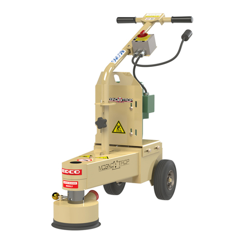
This manual suits for next models
1
Table of contents
Other Edco Grinder manuals

Edco
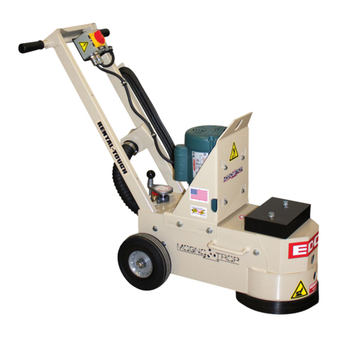
Edco SECNG-1.5L User manual

Edco
Edco 2-EC User manual

Edco
Edco MAGNA-TRAP TMC-7 Assembly instructions

Edco
Edco EDG-7 Datasheet

Edco
Edco MAGNA-TRAP TMC-7 Assembly instructions

Edco
Edco 2ECEGNG User manual

Edco
Edco TG-10 Assembly instructions

Edco
Edco MAGNA-TRAP TMC-7 Assembly instructions

Edco
Edco TG-10 Assembly instructions

Edco
Edco MAGNA-TRAP TMC-7 Assembly instructions