manuals.online logo
Brands
  1. Home
  2. •
  3. Brands
  4. •
  5. Edelbrock
  6. •
  7. Automobile Part
  8. •
  9. Edelbrock 66062 User manual

Edelbrock 66062 User manual

Catalog #66062
©2007 Edelbrock Corporation Page 1 of 3
Brochure #63-66062
Rev. 2/07 - DA/mc
®
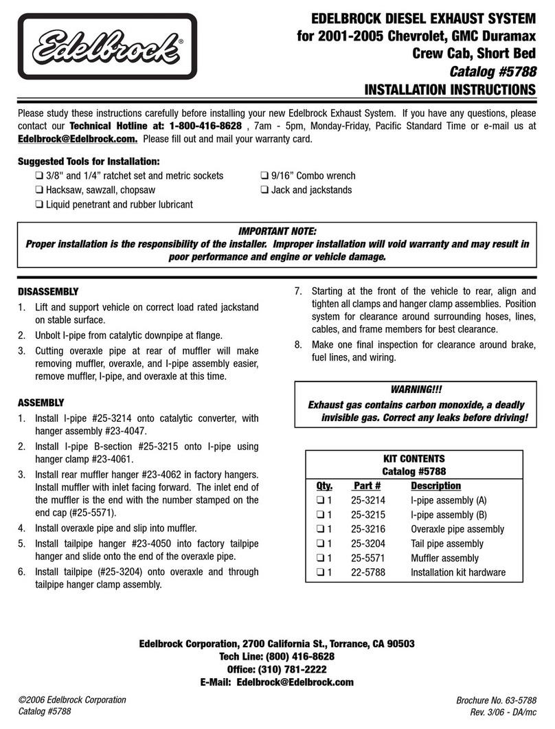
TUBULAR EXHAUST SYSTEM
For 1992 1/2 - 1999 Dodge Viper with 8.0L V10
Catalog #66062
INSTALLATION INSTRUCTION
Please study these instructions carefully before installing your new
Tubular Exhaust System
(TES). If you have any
questions, please contact our Technical Hotline at : 1-800-416-8628 from 7 am - 5pm, Monday-Friday, Pacific
Standard Time or e-mail us at [email protected].
TUBULAR EXHAUST SYSTEM: This stainless steel Tubular Exhaust System header is designed to improve the exhaust
efficiency of the Chrysler 8.0L V10 engine. A performance gain can be expected by the installation of the system. This
system does require welding for installation (see note below) and retains all O.E.M. emissions equipment. These
Tubular Exhaust Systems are street legal in all 50 states.
Suggested Tools Needed for Installation: This vehicle has some metric fasteners.
❑ Mig welder (recommended) or gas welder - Professional welding is highly recommended
❑3/8” rachet socket with extensions and universal 13mm and 15mm swivel sockets
❑ Combination set of open-end wrenches, SAE and metric
❑ Jackstands, screwdrivers, pliers, crescent wrench, hacksaw, etc.
❑ 3/8” ball end allen socket
❑Liquid penetrant, (GM #1052627) and anti-seize compound (GM #5613695)
SPECIAL NOTICE: This Edelbrock Tubular Exhaust System has received an Executive Order number (E.O.#) from the
California Air Resources Board (C.A.R.B.) making it legal for street use in all 50 states. To assist you with emission
equipment certification, we have included a silver fan shroud decal to help testing personnel verify the this part is a legal
replacement on the vehicle for which it is cataloged. The adhesive-backed decal should be affixed next to the existing
emission and engine specifications decal. Do not cover any part of your original emission decal.
WARNING: The use of "Thermal Wrap" or any aftermarket coating process will void the warranty on your Edelbrock
Tubular Exhaust Systems. Those products can cause excessive heat and moisture buildup resulting in corrosion and
failure of the system.
CAUTION: Due to higher underhood temperatures generated by TES, vehicles equipped with original spark plug wires
should have them replaced with high temperature plug wires for longer life.
IMPORTANT NOTE:
Proper installation is the responsibility of the installer. Improper installation will void warranty and may
result in poor performance and engine or vehicle damage.
Catalog #66062
©2007 Edelbrock Corporation Page 2 of 3
Brochure #63-66062
Rev. 2/07 - DA/mc
Disassembly
1. Disconnect negative battery cable.
2. Remove side exhaust covers. Note: Have someone
assist you to prevent damage to side covers or body.
3. Remove two O2 sensors from stock exhaust.
4. Remove rubber mounts and bracket holding stock
exhaust system at front of side pipes. They will not
be re-installed.
5. Remove bolts holding the exhaust pipe to exhaust
manifold.
6. Remove starter.
7. Number spark plug wires and remove from spark
plugs. Lay the wires over the rear of the engine to
prevent damage to wires.
8. Remove plastic spark plug wire separators from
valve cover area.
9. Remove top of heater air box (right side).
10. Unplug wire from temperature sending unit on left
cylinder head.
11. Remove the retaining nuts securing the heat shields
to exhaust manifolds. Note: The right side will come
off easily. The left side will only come off after all
manifold retaining bolts have been removed and the
manifold is completely loose. You may need to
remove the front bolt that holds the water pipe to
allow you to remove the heat shield and manifold.
12. Remove stock exhaust manifolds.
13. Clean gasket surfaces on cylinder heads.
Note: Be careful not to damage soft aluminum.
14. Cut stock exhaust at inlet of catalytic converter.
Assembly - Left Side
1. Install upper half of header from top along with new
gasket, bolts and washers supplied.
2. The thick hardened flat washers will be used on the
three slotted holes on each header flange.
3. Start all ten bolts but leave bolts loose at this time.
4. Install lower half of header from under car. Place
outlet end over frame rail and rotate into place.
Install gasket and 3/8" Allen head bolts and self-
locking nuts supplied.
5. Tighten cylinder head flange bolts evenly.
6. Tighten connector flange bolts evenly. Note: It is
very important that these bolts be tightened evenly.
Assembly - Right Side
1. The right side installs basically the same as the left
side.
Note: Remember all flange bolts must be tightened
evenly!
Flex Coupler Installation
1. Install flex coupler and elbow assembly using band
clamp onto outlet end of header. NOTE: The catalytic
converter must remain in stock location. Therefore,
the new turnout elbows will need to be shortened to
fit onto the inlet of your catalytic converters.
2. Once you have trimmed the outlet end of the turnout
elbows tack weld the catalytic converter inlet to
elbow.
3. Recheck all alignment and critical points, such as
outlet positioning, side pipe clearance to outer
covers catalytic converter location, etc.
4. If everything is correct, remove side pipe and flex
coupler/elbow assembly and weld together.
5. Reinstall onto car.
6. Repeat for other side.
7. Reinstall two O2 sensors and tie wrap sensor wires
away from hot parts with the tie wraps supplied.
NOTE: It may be necessary to re-route or re-position
the wires for the O2 sensors to make it easier to plug
in the O2 sensors.
Final Check
1. After all bolts have been properly installed and
torqued, reconnect battery cable, sparkplug wires,
separators,etc.
2. Start car and check for exhaust leaks. Do not drive
at this time.
3. After letting engine fully warm up, shut off and let
engine fully cool down.
4. Re-tighten all bolts and nuts on TES (Tubular Exhaust
System) headers.
INSTALLATION INSTRUCTIONS
Catalog #66062
©2007 Edelbrock Corporation Page 3 of 3
Brochure #63-66062
Rev. 2/07 - DA/mc
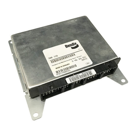
KIT CONTENTS
Catalog #66062
Qty.Description Qty.Description
❑1 Manifold left side (A section) #25-9101 ❑2 Manifold port gaskets
❑1 Manifold right side (A section) #25-9102 ❑2 Connector gaskets
❑1 Manifold left side (B section) #25-9103 ❑ 12 Lock nuts, cad-plated; 3/8”-16
❑1 Manifold right side (B section) #25-9104 ❑ 14 Socket head cap screws; 3/8”-16 x 1/4”
❑1 Cat. adapter left (3”) #25-9622 ❑4 Tie wraps; 11”
❑1 Cat. adapter right (3”) #25-9623 ❑ 20 Split lock washers; 5/16”
❑ 20 Header bolts; 5/16”-18 x 1” ❑6 Hardened washers; 5/16” i.d. x 3/4” o.d.
❑2 Coupler band clamps
Edelbrock Corporation
2700 California St.
Torrance, CA 90503
Tech Line: 1-800-416-8628
E-Mail: [email protected]
NOTE: To greatly reduced engine compartment temperature, we recommend the use of Edelbrock ceramic-coated,
stainless steel header heat shields Part #6700. These heat shields not only deflect heat out of the engine compartment
protecting underhood components, but they look great, too.

Other Edelbrock Automobile Part manuals

Edelbrock Victor Glidden 18 2858 Operation and maintenance manual

Edelbrock

Edelbrock Victor Glidden 18 2858 Operation and maintenance manual

Edelbrock 24502574 LT4 User manual

Edelbrock

Edelbrock 24502574 LT4 User manual

Edelbrock 66492 User manual

Edelbrock

Edelbrock 66492 User manual

Edelbrock 2925 User manual

Edelbrock

Edelbrock 2925 User manual

Edelbrock 5790 User manual

Edelbrock

Edelbrock 5790 User manual

Edelbrock Performer 1670 User manual

Edelbrock

Edelbrock Performer 1670 User manual

Edelbrock Performer Series 8059 User manual

Edelbrock

Edelbrock Performer Series 8059 User manual

Edelbrock Nitrous Systems 71831 User manual

Edelbrock

Edelbrock Nitrous Systems 71831 User manual

Edelbrock 8147 Owner's manual

Edelbrock

Edelbrock 8147 Owner's manual

Edelbrock 6501 User manual

Edelbrock

Edelbrock 6501 User manual

Edelbrock 15008 User manual

Edelbrock

Edelbrock 15008 User manual

Edelbrock 5253 User manual

Edelbrock

Edelbrock 5253 User manual

Edelbrock Camaro 5290 User manual

Edelbrock

Edelbrock Camaro 5290 User manual

Edelbrock 5229 User manual

Edelbrock

Edelbrock 5229 User manual

Edelbrock 72552 User manual

Edelbrock

Edelbrock 72552 User manual

Edelbrock 68752 User manual

Edelbrock

Edelbrock 68752 User manual

Edelbrock 65232 User manual

Edelbrock

Edelbrock 65232 User manual

Edelbrock 1903 User manual

Edelbrock

Edelbrock 1903 User manual

Edelbrock 5672 User manual

Edelbrock

Edelbrock 5672 User manual

Edelbrock 1478 User manual

Edelbrock

Edelbrock 1478 User manual

Edelbrock 15041 User manual

Edelbrock

Edelbrock 15041 User manual

Edelbrock Performer-Plus 2201 User manual

Edelbrock

Edelbrock Performer-Plus 2201 User manual

Edelbrock Performer 3764 User manual

Edelbrock

Edelbrock Performer 3764 User manual

Edelbrock PRO-FLO XT 3527 User manual

Edelbrock

Edelbrock PRO-FLO XT 3527 User manual

Popular Automobile Part manuals by other brands

STECK I-Bolt 71490 manual

STECK

STECK I-Bolt 71490 manual

Jeep 2008 Liberty installation instructions

Jeep

Jeep 2008 Liberty installation instructions

HURST COMPETITION PLUS Series installation instructions

HURST

HURST COMPETITION PLUS Series installation instructions

Atwood MPD 87083 Installation and operation manual

Atwood

Atwood MPD 87083 Installation and operation manual

LG ARNU48GBRZ4 manual

LG

LG ARNU48GBRZ4 manual

Axxess OESWC-CLASS2-RF installation instructions

Axxess

Axxess OESWC-CLASS2-RF installation instructions

Beckhoff AG2800 Documentation

Beckhoff

Beckhoff AG2800 Documentation

K&N Engineering KS-F160 instruction manual

K&N Engineering

K&N Engineering KS-F160 instruction manual

FormFit HD 21T18 installation instructions

FormFit

FormFit HD 21T18 installation instructions

AD Boivin ZX2 2008 Adjustment manual

AD Boivin

AD Boivin ZX2 2008 Adjustment manual

Axxess OESWC-7552-RF installation instructions

Axxess

Axxess OESWC-7552-RF installation instructions

Doug's Headers D3300 installation instructions

Doug's Headers

Doug's Headers D3300 installation instructions

AEM 21-724 installation instructions

AEM

AEM 21-724 installation instructions

AUTOTECH 10.715.014K 015K installation instructions

AUTOTECH

AUTOTECH 10.715.014K 015K installation instructions

Mitsubishi F5MR1 Workshop manual

Mitsubishi

Mitsubishi F5MR1 Workshop manual

Lippert Components Schwintek In-Wall Troubleshooting and component replacement

Lippert Components

Lippert Components Schwintek In-Wall Troubleshooting and component replacement

SAF-HOLLAND SK RB 9022 W INTEGRAL Repair manual

SAF-HOLLAND

SAF-HOLLAND SK RB 9022 W INTEGRAL Repair manual

Flowmaster 814110 installation instructions

Flowmaster

Flowmaster 814110 installation instructions

manuals.online logo
manuals.online logoBrands
  • About & Mission
  • Contact us
  • Privacy Policy
  • Terms and Conditions

Copyright 2025 Manuals.Online. All Rights Reserved.