manuals.online logo
Brands
  1. Home
  2. •
  3. Brands
  4. •
  5. EdilKamin
  6. •
  7. Indoor Fireplace
  8. •
  9. EdilKamin WIDRO 85 Service manual

EdilKamin WIDRO 85 Service manual

WIDRO 85
WIDRO 85 CS
WOOD-BURNING
THERMO-FIREPLACE
For all updates visit www.edilkamin.com
EN Installation, use and maintenance page 2
2
ENGLISH
The undersigned EDILKAMIN S.p.A., with registered
office in Via Vincenzo Monti 47 - 20123 Milan (Italy) - Tax
ID Code and VAT number 00192220192
Declares under its own liability that the following
product conforms to EU Regulation 305/2011 and to the
harmonised European standard EN 13229:2001+A1:20
03+A2:2004+AC:2006 +AC:2007
WOOD-BURNING THERMO-FIREPLACE, trade name
EDILKAMIN, models WIDRO 85 and WIDRO 85 CS
SERIAL NO.: Rating plate reference
WIDRO 85 and WIDRO 85 CS: Declaration of perfor-
mance (DoP - EK no. 203)
The liability of the manufacturer is limited to the supply
of the product.
The original language of this manual is Italian
CONTENTS
Safety Information xx
General Information xx
Installation xx
Installation xx
Hydraulic Installation xx
Instructions for Use xx
Maintenance xx
Maintenance xx
USER/INSTALLER
3
ENGLISH
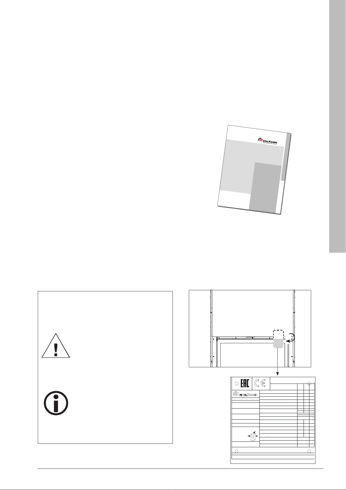
The product is uniquely identified by a number, the
“counterfoil”, which is indicated on the warranty certificate.
Please keep:
• the warranty certificate accompanying the product
• the purchase receipt given to you by the retailer
• the declaration of conformity given to you by the installer.
Check local regulations.
The warranty conditions are given in the warranty certificate
accompanying the product and on the website www.
edilkamin.com.
MEANING OF SYMBOLS
In some parts of the manual the following symbols
are used:
INFORMATION:
failure to comply with these
requirements will compromise
product use.
PLEASE NOTE:
carefully read and understand the
message in question, since failure
to follow the instructions in it could
cause serious damage to the
product and put the safety of those
using it at risk.
Dear Sir/Madam
Congratulations on choosing our product. Before you use it,
please read this manual carefully, to get the best from your
new appliance in total safety.
This manual is an integral part of the product.
Keep it with care for the service life of the product.
If you lose it, you can request a copy or download it from
www.edilkamin.com
Readers of this manual
This manual is addressed to:
• those who will use the product at home (“USER”);
• the technician who will install the product (“INSTALLER”).
The target person of each page is indicated in a band at the
bottom of the page (USER or INSTALLER).
After unpacking the product, check the condition and
completeness of the contents.
In the event of error, immediately contact the retailer where
the purchase was made, providing them with a copy of the
warranty booklet and the sales receipt.
The appliance must be correctly sized, installed, maintained
and operated in compliance with local and national law and
European regulations. For the installation, and for anything
not specifically indicated in the manual, observe local
regulations.
The diagrams provided in this manual are for illustration
purposes only: they do not always strictly refer to your
specific model, and are not binding in any way.
CERTIFICATO
DI GARANZIA
, &HUWL¿FDWRGLJDUDQ]LD 
AL
dHUWL¿NDWsJDUDQFLH
CZ=iUXþQtOLVW
D*DUDQWLH]HUWL¿NDW
DK *DUDQWLFHUWL¿NDW
E &HUWL¿FDGRGHJDUDQWtD 
F &HUWL¿FDWGHJDUDQWLH
GR ȆȚıIJȠʌȠȚȘIJȚțȩİȖȖȪȘıȘȢ 
H*DUDQFLDEL]RQ\ODW
HR -DPVWYHQLOLVW
NL *DUDQWLHEHZLMV 
P&HUWL¿FDGRGHJDUDQWLD
PL *ZDUDQFMDREHMPXMąFD 
RO &HUWL¿FDWGHJDUDQĠLH 
RUS Ƚɚɪɚɧɬɢɣɧɵɟɨɛɹɡɚɬɟɥɶɫɬɜɚ 
SLO *DUDQFLMVNLOLVW
SK =iUXþQêOLVW 
SRB *DUDQWQLOLVW 
UK :DUUDQW\FHUWL¿FDWH 
USER/INSTALLER
CE
The product’s CE marking plate is located above the glass,
under the casing, and can also be accessed once the
product has been installed.
kW
kg/h
B
R
L
bar
Max fuel consumption/ Max. Verbrauch vonBrennmaterial
Consommation max. de combustible / Consumo massimo
kW
kW
kW
Heat input / Thermische Leistungeingefuhr t
Puissance calorique introduite / Potenza termica introdotta
Nominal heat output / Gesamt Nennleistung
Puissance normal total / Potenzanominale totale
Boiler output / Leistung Wasserseitig
Puissance a l'eau / Potenzaresa all'acqua
Space heating output / Leistung Raum
Environnement puissance / Potenzaresa all'ambiente
Max water pressure / Max. Wasserdruck
Pression eau max. / Pressione massima acqua
%
%
Pa
Maximum allowable temperature/Maximal zulassige temperatur
Temperaturemaximale admissible/Massima temperatura consentita
W
mg/Nm
3
-
Function / Betrieb
Model / Modell / Modele / Modello
Ā C
V
Hz
-
Eciency / Wirkungsgrad / Rendement / Rendimento
NOx emissions (al 13% O2)
-
-
-
-
Read and follow instructions! / Bedienungsanleitung lesen und befolgen! / Lire et suivre les instructions! / Leggeree seguire le istruzioni
-
-
WIDRO 85 -
-
-
-
I-20045 Lainate (MI), via Mascagni 7
Notied Body
EN 13229:2001+A1:2003+A2:2004+AC:2006+AC:2007
Funtionament / Funzionamento
Serial number / Seiennummer
Numero de serie / Numero di serie
System / Systeme / Sistema
1880
Inset solid fuel
Kamineinsätze für feste Brennstoe
insert à combustibles solides
Inserto a combustibile solido
OGC emissions (al 13% O2)
7.5
34.7
29.7
18.2
11.5
85.70
856.0
13.0
112.0
64
238
mg/Nm
3
mg/Nm
3
mg/Nm
3
3
-
0.068 -
-
-
INT
W
-
300000
Yearof construction/Produktionsiahr
Annee de construction/Anno di costruzione
Ā C
90.0
21 DoP n. EK203
Use only with proper fuel/Nur zugelassenen Brennsto verwenden/A utiliser seulement avec un combustible conforme.
Utilizzare solo combustibile conforme Wood logs / Holzscheit / Bûches de bois / Ciocchi di legno
Operating voltage / Betriebsspannung
Tensiond'alimentation / Tensione di alimentazione
Rated input power /Nenn-Stromleistung
Puissance electrique nominale/Potenza elettrica nominale
Flue gas temperature / Abgastemperatur
Temperaturedes fumees / Temperatura dei fumi
Dust emissions / Staubausstoss
Emissions poussieres / Emissioni di polveri (al 13% 02)
CO Emission (at 13% O2)/CO-Ausstoss (bei 13 % O2)
Emissions CO (a 13% O2)/Emissioni di CO (al 13% 02)
Reduc.
Reduz.
Reduite
Ridotta
Nominal
Rated
Nominale
Nominale
Minimum clearence distance from combusti-
ble materials / Mindestabstand von
brennbaren Werkstoen/ Distance minimum
des materiaux inammables
Maximum electrical power/Maximale elektrische Leistung
Puissance electrique maximale/Potenza elettrica massima
cd 3710662 ed. A 06.21
Rated frequency / Nennfrequenz
Frequence nominale / Frequenza nominale
R: 0 mm
B: 0 mm
L: 0 mm
3
4
ENGLISH
SAFETY INFORMATION
• The product is not designed for use by people,
including children, with limited physical, sensory
and mental abilities.
• The product is designed to burn dry wood in
the quantities and according to the procedures
described in this manual.
• The appliance is designed for indoor use and in
areas with normal humidity conditions.
• The product must be installed in rooms where
there are no fire risks.
• In the event of fire, call the competent authorities.
Do not try to put the fire out with jets of water.
Safety risks may be caused, amongst other things, by:
• contact with fire and hot parts (e.g. glass panel
and pipes). DO NOT TOUCH HOT PARTS and,
when switched off and still hot, always wear the
gloves supplied. Failure do so may result in burns.
• Use of improper ignition aids (e.g. alcohol). DO
NOT IGNITE OR BOOST THE FLAME WITH FLUID
SPRAYS OR A FLAME TORCH. Serious risk of
burns, damage and injury.
• Use of fuel other than dry wood. DO NOT BURN
WASTE MATTER, PLASTIC OR MATERIALS
OTHER THAN DRY WOOD IN THE COMBUSTION
CHAMBER. The product may become soiled, the
flue may catch fire, and environmental damage
may ensue.
• Use of fuel in quantities other than those
recommended. DO NOT OVERLOAD THE
COMBUSTION CHAMBER. You risk buckling
the combustion chamber and creating personal
risks in attempts to resolve this problem and also
irreversible changes in colour of the paints on
metal parts.
• Cleaning the combustion chamber when hot. DO
NOT CLEAN THE COMBUSTION CHAMBER WITH
A VACUUM CLEANER WHILE IT IS HOT. Risk of
damage to the cleaner and smoke in the room.
• Cleaning the fumes duct with various substances.
DO NOT ATTEMPT HOME-GROWN CLEANING
SOLUTIONS USING INFLAMMABLE PRODUCTS
Risk of fire and blowback.
• Cleaning the glass pane while hot with unsuitable
cleaning products. DO NOT CLEAN HOT GLASS
WITH WATER. ONLY USE RECOMMENDED
GLASS CLEANING PRODUCTS OR A DRY
CLOTH. Risk of cracking and permanent,
irreparable damage to the glass.
• Storing flammable materials within the safety
clearance indicated in this manual. DO NOT
PLACE LAUNDRY ON THE PRODUCT. DO NOT
PLACE DRYING RACKS WITHIN THE SAFETY
CLEARANCE. Keep all inflammable fluids away
from the appliance when in use. Fire hazard.
• Blocking the aeration vents and air intakes in the
room. DO NOT BLOCK THE AERATION VENTS
OR FLUE. Risk of smoke returning into the room
with consequent damage and injury.
• Use of the product as a support or ladder. DO
NOT CLIMB ONTO THE PRODUCT OR USE IT AS
A SUPPORT. Risk of damage and injury.
• Use of the product with the combustion chamber
open. DO NOT USE THE PRODUCT WITH ITS
DOOR OPEN.
• Adding fuel and opening the door, approaching the
fire while wearing baggy, inflammable garments.
DO NOT open the door or approach the glass with
baggy, inflammable garments as they could easily
catch fire.
• Incandescent material projected from the open
door. DO NOT throw incandescent material
outside the appliance. Fire hazard.
If you have doubts, please do not take any action, but
contact the dealer or the installer.
• NEVER OPERATE THE THERMO-FIREPLACE
WITHOUT WATER IN THE CIRCUIT.
• RUNNING WHILE “DRY” MAY DAMAGE THE
THERMO-FIREPLACE.
• The thermo-fireplace is designed to heat water
through combustion of wood in the combustion
chamber.
ONLY LIGHT THE PRODUCT WITH
THE REFRACTORY ELEMENTS IN
PLACE.
USER/INSTALLER
5
ENGLISH
Available with open vessel - Widro 85 and closed vessel - Widro 85 CS.
IN ITALY:
• ONLY THERMO-FIREPLACES WITH COIL CON-
TROLLED BY VST THERMAL DISCHARGE VALVE (not
included) CAN BE INSTALLED WITH A CLOSED-VESSEL
SYSTEM
For installations with closed vessel:
• Correct installation of the system is the responsibility
of the installer who shall take into consideration local
regulations.
The thermal discharge valve must be connected to the
cooling circuit with a pressure of at least 1.5 bar.
AL = coil supply, always pressurised (minimum) 1.5 bar
VST = thermal discharge valve
S = discharge
The valve (not included) may
be installed as desired on any one of the
coil connectors.
• The system must have another dedicated expansion
vessel for the thermo-fireplace, selected on the basis of
the volume of water in the system itself.
INTRODUCING THE RANGE
only for Widro 85 CS
USER/INSTALLER
Fig. 1
Fig. 2
6
ENGLISH
EDILKAMIN S.p.A. reserves the right to modify the product at its own discretion and
without prior notice, with a view to improvements.
TECHNICAL DATA FOR SIZING THE FLUE
which must in any case satisfy the requirements of this sheet and the installation instructions
Widro 85 - Widro 85 CS
Nominal power
Smoke temperature at smoke outlet 286 °C
Minimum draught 8 Pa
Smoke flow rate 18.1 rps
TECHNICAL DATA
Intermittent combustion device
Position five pieces of dry wood with 33-cm length, placed horizontally.
* The calculation of fuel consumption assumes a calorific value of 4.6 kW/kg for wood.
** The heatable volume is calculated based on the assumption of a heating demand of 33 Kcal/m³ hour.
The product can work safely even with greater draught.
Excessive draught could cause the product to switch off and/or lower its performance.
NOTE: the smoke outlet diameter does not match the chimney system diameter, which must be
sized accordingly.
TECHNICAL CHARACTERISTICS in accordance with EN 13229
The data shown below refers to the actual installation and use and was taken during the certification phase by a
notified body under the conditions specified by the standard.
The results were obtained with the glass cleaning system off, by the installer.
Widro 85 - Widro 85 CS
Nominal power
Burned thermal power 34.7 kW
Nominal thermal power 29.7 kW
Power available to water 18.2 kW
Yield 85.7 %
CO emissions at 13% O20.068 %
Average smoke temperature 238 °C
Draw 11 Pa
Fuel consumption * 7.5 kg/h
Maximum operating pressure 3 bar
Maximum operating temperature 238 °C
Water content 115 litres
Delivery to heating system (male) 1” inch
Return from heating system (male) 1” inch
Heatable volume ** 775 m³
Smoke outlet diameter 200 mm
Air intake diameter 130 mm
Weight including packaging 561 kg
Environmental class according to Italian Min. Decree 186 4 stars
Energy efficiency class in accordance with EU regula-
tion 2015-1186 (Classes A++/G) A+
USER/INSTALLER
7
ENGLISH
DIMENSIONS
WIDRO 85 (dimensions in cm)
USER/INSTALLER
102
103
99
Ø 20
Ø 13
85
51
72.5
71
139
74
71
69.5
* maximum extension of feet 8 cm
*164/172
82
31
52
55
delivery 1”
delivery 1”
return 1”
8
ENGLISH
DIMENSIONS
WIDRO 85 CS (dimensions in cm)
USER/INSTALLER
102
1/2” connectors for coil
* maximum extension of feet 8 cm
85
51
103
99
Ø 20
72.5
71
69.5
Ø 13 int.
71
139
*164/172
74 82
31
52
55
delivery 1”
delivery 1”
return 1”
9
ENGLISH
INSTALLATION
PREPARATION AND UNPACKING
The packaging materials are neither toxic nor noxious and do not require special disposal.
The user is responsible for storing, disposing of and recycling them in a regulatory fashion.
Always move the stove vertically with suitable equipment and in compliance with safety regulations.
Do not turn the package over, and handle all parts requiring installation with care.
TO REMOVE THE PRODUCT FROM THE PALLET
Remove the screws
Remove the screws (V)
securing the product to the pallet, located on the feet.
Remove the product from the pallet, taking special care to protect the door and its glass pane from impacts.
(V)
INSTALLER
10
ENGLISH
HANDLING OF THE PRODUCT
SHIFTING OF THE PRODUCT WITH WHEELS
NEAR THE INSTALLATION POSITION
The fireplace is equipped with feet (B) and wheels
(C).
Screw on the feet to use the wheels.
PLEASE NOTE:
If the fireplace is not level there may
be problems with the door's sliding
movement.
USE THE WHEELS ONLY FOR SMALL
MOVEMENTS. DO NOT DRAG THE
PRODUCT.
PRODUCT.
THE FEET MAY GET DAMAGED. USE
THE WHEELS, after screwing the feet on.
PICK-UP POINTS FOR HANDLING
The monobloc is equipped with four hooks to facilitate
its transport (A).
Make sure that the product remains
balanced during handling. FEET
The feet are used to distance the fireplace from the
floor and to level the hearth.
They can be adjusted by a maximum of 10 cm.
After positioning the fireplace, reposition the feet.
LOOSEN THE LOCKING SCREWS ON THE SIDE OF THE DOOR ONLY AFTER THE PRODUCT HAS BEEN
POSITIONED. DO NOT SHIFT THE PRODUCT WITHOUT THE LOCKING SCREWS.
C
C
B
B
A
INSTALLER
11
ENGLISH
INSTALLATION
DELIVERY
The packaging can provide a useful indication of the product’s condition. Check the packaging on receipt and report
any anomalies to the reseller straight away.
The packaging consists of a single pack with the contents as below.
Description
Number in
the figure
below
Quantity
(pcs)
Use
Fireplace 1 *
Side and rear refractory
elements
5
Handle for
lifting the door
with screws
(1) 1 can be used either as a fixed handle (by fastening it with
the screws) or as a detachable handle, using the relevant
bushes.
INSTALLER
1
12
ENGLISH
INSTALLATION
LOOSEN THE SCREWS ONLY AFTER THE PRODUCT HAS BEEN POSITIONED.
DO NOT SHIFT THE PRODUCT WITHOUT THE LOCKING SCREWS.
LOOSEN THE LOCKING SCREWS ON THE SIDES IN ORDER TO LIFT THE DOOR.
locking screws
INSTALLER
13
ENGLISH
INSTALLATION
INTERNAL REFRACTORY ELEMENTS
Assembly sequence for REFRACTORY ELEMENTS:
1+2) Position the LH SIDE element.
3) Position the REAR element.
4+5) Position the RH SIDE element.
6) Position (A) REFRACTORY ELEMENTS on top.
ONLY LIGHT THE PRODUCT WITH THE REFRACTORY ELEMENTS IN PLACE.
2)1) 3)
5)4)
INSTALLER
6)
(A)
14
ENGLISH
INSTALLATION
SELF-CLOSING DOOR
The fireplace is delivered with the door balanced, that is, it does not drop automatically once raised.
To make the door self-closing, one or more plates (P) must be applied to the inner frame for the door.
To access the inner frame of the door, remove the cover door located on the fireplace casing on both sides.
without plates
(standard)
with plates
(added during the installation phase)
NOT self-closing self-closing
P
A
INTERNAL VIEW OF THE PLATES ON THE DOOR FRAME
Remove the casing (M)
(M)
INSTALLER
15
ENGLISH
INSTALLATION
REMARKS ON INSTALLATION
Note that:
Note that:
•
•
the appliance must be installed by authorised
technical personnel;
•
•
the appliance must be installed and operated
in compliance with local and national law and
European regulations;
•
•
if installed in a condominium, the appliance must
be approved by the administrator.
Here are a few general instructions, although these do
not obviate the need to comply with local regulations
and do not affect the installer's liability for the
installation.
installation.
Checking the suitability of the installation
space
• The room must have a volume of at least 70 m3.
• The appliance may not be installed in a bedroom,
bathroom or in the same room as other equipment
which draws air for combustion from the room
itself, or in any area with an explosive atmosphere.
Any extraction fans operating in the same room or
area as the product may affect its draught.
• In Italy, check the compatibility pursuant to UNI
10683 and UNI 7129 in the presence of gas-fired
products.
• The floor must be able to bear the weight of the
product and its accessories.
When installing the product, leave enough
space to allow easy access for cleaning the
product and the chimney system.
In some nations, installations with multiple
flues are permitted under certain conditions.
Depending on regional regulations, further
safety systems are necessary in the case of
connection to multiple flues. Your chimney
sweep/technician will be able to provide
further details.
Power lines
Power lines
no power lines must be present in the walls
and in the ceilings within the recessed area
of the product.
of the product.
INSTALLER
16
ENGLISH
INSTALLATION
Protection from heat and safety clearances.
The surfaces of the building adjacent to the product
must be protected against overheating.
The insulation to be used will depend on the type of
surface in question.
Check on the chimney system’s data plate the safety
distances to be kept in the presence of combustible
materials and the type of insulating material to be used.
MINIMUM SAFE DISTANCES FROM
FLAMMABLE MATERIALS
Rear = 0
Side = 0
Front = 2000
INSTALLER
17
ENGLISH
INSTALLATION
FLUE SYSTEM
FLUE SYSTEM
(
(
Fumes duct, flue and chimney pot
)
)
This chapter has been drawn up pursuant to European
regulations EN 13384, EN 1443, EN 1856 and EN
1457. The installer must observe both these and any
other local regulations. This manual does not in any
way substitute such regulations.
The product must be connected to a smoke exhaust
system which ensures that the smoke produced by
combustion is expelled in complete safety.
Before positioning the appliance, one must check that
the flue is suitable.
SMOKE DUCT, FLUE
SMOKE DUCT, FLUE
The smoke duct
(which connects the combustion
chamber smoke outlet with the flue inlet)
chamber smoke outlet with the flue inlet) and the flue
itself must, among other regulatory requirements:
• receive the smoke from a single product (the outlets
of multiple appliances may not be conveyed into a
single flue)
• have a mainly vertical course (no horizontal sections
and bends of over 45° are permitted)
• have no downwards sloping sections
• have a preferably circular internal cross section and
nevertheless with a ratio of the sides of less than 1.5.
• end at roof level with a proper chimney pot: the
flue may not discharge directly on the wall or into an
enclosed space, even if the space in question is open
to the sky
• be made of material rated fire reaction class A1 per
UNI EN 13501 or equivalent national regulations
• be certified, with a chimney plate if metal
The smoke outlet diameter does not
match the chimney system diameter,
which must be sized accordingly.
The chimney system must be sized
by an expert in accordance with the
regulations in force.
INSTALLER
18
ENGLISH
INSTALLATION
THE SMOKE DUCT
THE SMOKE DUCT
• if it is metal, it must have CE marking (EN 1856-2) or
some similar national standard marking;
• may not be made of flexible metal material;
• in order to check the flow, it is recommended to use
a damper if the draught is above 25 Pa.
THE FLUE
THE FLUE:
• it must have a draught capable of creating
depressurisation, which is ideally around 12 Pa.
Lower draughts may lead to leaks of smoke when
the door is opened; higher values tend to generate
fast combustion and reduced efficiency
• must be correctly sized to satisfy the requirements
for flue gas discharging (EN 13384-1)
• should preferably be insulated, in steel with a
circular internal section. If rectangular, the inner
corners must have a radius of not less than 20
mm, with a ratio of the internal dimensions of <1.5
• must normally be at least 4 metres in vertical length
• must be waterproof and thermally insulated to
ensure proper draught
• preferably provide a collection chamber for
unburnt fuel and condensates
• must be at least in the T400 category with
appropriate resistance against soot igniting
• if pre-existing, must be clean, to prevent fire
hazards.
Infiltration of water from condensation
through the flue must be strictly avoided.
If necessary, an anti-condensate ring
should be installed. Ask your chimney
sweep for details.
Damage caused by water from
condensation is excluded from the warranty.
THE CHIMNEY POT
THE CHIMNEY POT
• must be anti-downdraught
• must have an internal cross section equivalent to
that of the flue and a fumes outlet at least double
that of the interior of the flue
• for dual flues (which should be spaced at least 2
m apart) the chimney pot of the flue receiving the
fumes from the solid fuel appliance or that from
the higher storey, must be at least 50 cm higher
• needs to beyond the back flow zone
• it must allow for maintenance of the chimney
INSTALLER
19
ENGLISH
INSTALLATION
EXTERNAL COMBUSTION AIR INTAKE (A)
To restore the oxygen burnt during operation, it is
necessary to have an adequate air intake, pursuant to
local regulations, of 200 cm2.
In accordance with local regulations, the air intake can
be mounted outside or in suitable rooms not subject
to depression.
The cladding must have the grille at floor level so that
combustion air can enter the product.
DIRECT AIR INTAKE
DIRECT AIR INTAKE
Install an air intake with an effective size (net of the
mesh or other protective equipment) that is at least
equal to that of the air intake at the back of the product.
Choose the diameter based on the load losses.
Connect the air intake to the appliance's air intake with
a pipe that may also be flexible. Increase the diameter
of the pipe if the pipe is not smooth: assess any load
loss.
A maximum length of 5 metres is recommended, with
no more than 3 bends depending on the draft of the
flue.
The air maybe drawn from an adjacent room only if:
• the flow is taken from permanent, unobstructed
openings communicating with the outdoors
• the air pressure in the adjacent room is never
reduced to a level below outdoor pressure
• the adjacent room is not a garage, subject to fire
hazard, a bathroom or a bedroom
• the adjacent room is not a shared room in the
condominium.
In Italy, UNI 10683 provides that ventilation is sufficient
even if a pressure difference between the outdoors
and indoors of no more than 4 PA is guaranteed (UNI
EN 13384-1). The installer who issues the declaration
of conformity is responsible for ensuring these
conditions.
INSTALLER
(A)
(A)
20
ENGLISH
ORIENTATION OF AIR INTAKE ON LEFT-HAND
SIDE (P)
SIDE (P)
IT IS
IT IS
possible to position the air intake on the left-hand side
of the chimney.
of the chimney.
Proceed as follows:
Proceed as follows:
•
•
Remove pre-cut part
Remove pre-cut part
(P)
(P)
from the left-hand side.
•
•
Unscrew the plate
Unscrew the plate
(P1)
(P1)
on the right-hand side to be
reused to close the hole of the previous air intake,
closing the right-hand side.
•
•
Screw on the pre-cut part
(P)
(P)
on the right-hand side in
the place of
the place of
(P1)
(P1)
.
.
INSTALLATION
INSTALLER
(P)
(P)
(P1)
(P1)

This manual suits for next models

1

Other EdilKamin Indoor Fireplace manuals

EdilKamin H2OCEANO 15 CS Quick start guide

EdilKamin

EdilKamin H2OCEANO 15 CS Quick start guide

EdilKamin WINDO3 50 Service manual

EdilKamin

EdilKamin WINDO3 50 Service manual

EdilKamin H2OCEANO 15/CS Quick start guide

EdilKamin

EdilKamin H2OCEANO 15/CS Quick start guide

EdilKamin PELLKAMIN 12 Quick start guide

EdilKamin

EdilKamin PELLKAMIN 12 Quick start guide

EdilKamin SCREEN 80 Quick start guide

EdilKamin

EdilKamin SCREEN 80 Quick start guide

EdilKamin INPELLET 54 Quick start guide

EdilKamin

EdilKamin INPELLET 54 Quick start guide

EdilKamin BASIC Quick start guide

EdilKamin

EdilKamin BASIC Quick start guide

EdilKamin SIDE 50x50 PLUS N Quick start guide

EdilKamin

EdilKamin SIDE 50x50 PLUS N Quick start guide

EdilKamin PELLKAMIN 10 EVO PLUS Installation and operating instructions

EdilKamin

EdilKamin PELLKAMIN 10 EVO PLUS Installation and operating instructions

EdilKamin IDRO 50 Quick start guide

EdilKamin

EdilKamin IDRO 50 Quick start guide

EdilKamin PELLKAMIN 12 Quick start guide

EdilKamin

EdilKamin PELLKAMIN 12 Quick start guide

EdilKamin LOGO Quick start guide

EdilKamin

EdilKamin LOGO Quick start guide

EdilKamin IDRO 30 Quick start guide

EdilKamin

EdilKamin IDRO 30 Quick start guide

EdilKamin FORMA Quick start guide

EdilKamin

EdilKamin FORMA Quick start guide

EdilKamin DOUBLE Quick start guide

EdilKamin

EdilKamin DOUBLE Quick start guide

EdilKamin TERA H 25 User manual

EdilKamin

EdilKamin TERA H 25 User manual

EdilKamin H2OCEANO 15 CS Manual

EdilKamin

EdilKamin H2OCEANO 15 CS Manual

EdilKamin H2OCEANO 15 CS Quick start guide

EdilKamin

EdilKamin H2OCEANO 15 CS Quick start guide

EdilKamin INPELLET 49 Quick start guide

EdilKamin

EdilKamin INPELLET 49 Quick start guide

EdilKamin IDROPELLBOX Quick start guide

EdilKamin

EdilKamin IDROPELLBOX Quick start guide

EdilKamin IDROPELLBOX 30 Quick start guide

EdilKamin

EdilKamin IDROPELLBOX 30 Quick start guide

EdilKamin Firebox Deco Series Quick start guide

EdilKamin

EdilKamin Firebox Deco Series Quick start guide

EdilKamin FLAT 1 Series Quick start guide

EdilKamin

EdilKamin FLAT 1 Series Quick start guide

EdilKamin Point Plus Quick start guide

EdilKamin

EdilKamin Point Plus Quick start guide

Popular Indoor Fireplace manuals by other brands

Amazon B081244SRH manual

Amazon

Amazon B081244SRH manual

Lennox Hearth Products B-Vent Series EBVCL supplementary guide

Lennox Hearth Products

Lennox Hearth Products B-Vent Series EBVCL supplementary guide

Baxi 941 owner's guide

Baxi

Baxi 941 owner's guide

Regency Fireplace Products Greenfire GFI300L Owners & installation manual

Regency Fireplace Products

Regency Fireplace Products Greenfire GFI300L Owners & installation manual

HearthStone Clydesdale II 8492 owner's manual

HearthStone

HearthStone Clydesdale II 8492 owner's manual

Superior VD1824PM Installation and operation instructions

Superior

Superior VD1824PM Installation and operation instructions

Planika L-Fire instruction manual

Planika

Planika L-Fire instruction manual

Lennox MPDT33RNM installation instructions

Lennox

Lennox MPDT33RNM installation instructions

Empire Comfort Systems White Mountain Hearth DVCX36FP91K-3 Installation instructions and owner's manual

Empire Comfort Systems

Empire Comfort Systems White Mountain Hearth DVCX36FP91K-3 Installation instructions and owner's manual

Continental Fireplaces 36-1 Series Installation and operation manual

Continental Fireplaces

Continental Fireplaces 36-1 Series Installation and operation manual

MODE KS1460 Single Installation & service instructions

MODE

MODE KS1460 Single Installation & service instructions

Black & Stone VFC 1100C Owner's manual and installation guide

Black & Stone

Black & Stone VFC 1100C Owner's manual and installation guide

Archgard 22-DVI24N-3 Installation, operation and maintenance manual

Archgard

Archgard 22-DVI24N-3 Installation, operation and maintenance manual

Regency Fireplace Products CARDINIA Owners & installation manual

Regency Fireplace Products

Regency Fireplace Products CARDINIA Owners & installation manual

Desa LGFB32C Safety information and installation manual

Desa

Desa LGFB32C Safety information and installation manual

Xaralyn Levico 70 manual

Xaralyn

Xaralyn Levico 70 manual

Empire Comfort Systems DVP20MS Installation instructions and owner's manual

Empire Comfort Systems

Empire Comfort Systems DVP20MS Installation instructions and owner's manual

furniture123 AGL052 user manual

furniture123

furniture123 AGL052 user manual

manuals.online logo
manuals.online logoBrands
  • About & Mission
  • Contact us
  • Privacy Policy
  • Terms and Conditions

Copyright 2025 Manuals.Online. All Rights Reserved.