- 27 -
ENGLISH
INSTALLATION
If combining with a pre-fabricated Edilkamin covering, to deŎ-
ne the exact positioning of the thermo Ŏreplace, it is important
to take the chosen covering model into consideration.
The positioning is implemented according to the model chosen
(refer to the installation instructions found inside the packaging
of each thermo Ŏreplace covering).
Always ensure the thermo Ŏreplace is level during the installa-
tion process.
- Drill a hole into the wall or the ŏooring for the external air
intake and connect the air adjustment mechanism to the hole as
described in the chapter called “external air inlet”.
- Use a stainless steel ŏue to connect the thermo Ŏreplace to the
chimney ŏue, adhering with the diameters indicated in the spe-
ciŎcations table and the guidelines given in the chapter called
“chimney ŏues”.
- Verify that all moving parts function properly before setting
the thermo Ŏreplace covering in place.
- This system must be tested and ignited for the Ŏrst time
before the covering is set in place.
INSTALLATION COVERING, FIREPLACE MAN-
TEL AND VENTILATION OUTLETS
The base of the thermo Ŏreplace covering must allow the
internal air to be recycled. Therefore, suitable slots or apertures
must be made for the air to pass through. Parts of the thermo
Ŏreplace covering that are made of marble, stone and bricks
must be mounted with a small gap between them and the Ŏre-
place so as to prevent possible breakage due to expansion and
excessive overheating.
Wooden parts must be protected by Ŏre resistant panels and
Practical advice
It is recommended to keep the radiators closed in the room
where the thermo Ŏreplace is installed; The heat emitted from
the outlet may be sufŎcient to heat.
- An incomplete combustion process causes excessive fouling
on the heat exchanger pipe.
To prevent this you must:
- burn dry wood.
- ensure the hearth contains a bed of embers and burning car-
bon before adding more wood.
- place larger logs together with smaller ones.
- make sure the temperature of the return water is at least 50 °C
(use temperature control valve).
Igniting the Ŏreplace
- Ensure that at least one radiator is always open.
- Actuate the switches of the electronic regulator.
- Place a pile of medium-thin dry wood in the thermo Ŏreplace
and ignite the Ŏre.
- Wait a few minutes until it reaches sufŎcient combustion.
- Close the door
- Set the thermostat on the electronic regulator (*) at a tempera-
ture between 50 and 70° C.
NOTE: There may be a slight smell of paint the Ŏrst few times
it is ignited, however, this will disappear quickly.
no part must touch the thermo Ŏreplace, on the contrary, there
must be an appropriate distance of at least 1 cm to allow the
air to ŏow, preventing heat accumulation. The Ŏreplace mantel
can be made of Ŏreproof plasterboard panels or gypsum board
and, however, of completely Ŏreproof material. Air should be
allowed to ŏow inside the Ŏreplace mantel (through the gap
between the door and the beam). Through convective motion,
the air will ŏow out from the grille installed at the top, resulting
in heat recovery and preventing excessive overheating.
The Ŏreplace mantel must have appropriate openings to carry
out maintenance on the Ŏttings.
In addition to that mentioned above, please consider the in-
dications stipulated in the UNI 10683 standard, paragraphs
4.4 and 4.7: “insulation, Ŏnishing, Ŏreplace covering and
safety recommendations”.
Insulating mats must be applied when using an installation
KIT so as to protect it from the heat radiation emitted by
the thermo Ŏreplace.
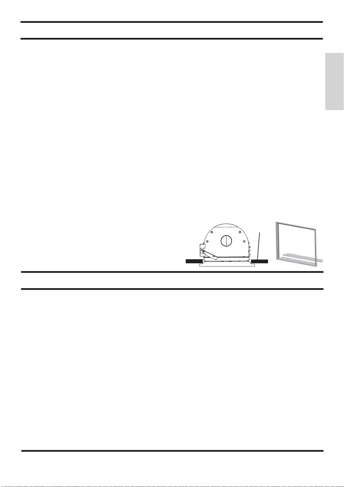
INLET FRAME (OPTIONAL)
To facilitate coupling with the covering’s components, the ther-
mo Ŏreplace can be Ŏtted with a frame (A) to be applied on the
front of the inlet.
INSTRUCTIONS FOR USE
3-way valve
- During ignition the 3-way valve (*) diverts the ŏow of water,
forcing it to return directly to the thermo Ŏreplace;
when the set temperature is reached, the 3- way valve (*)
diverts the ŏow to the system (does not depend on the kit
installed).
By-pass damper
- When the door is closed, the by-pass damper automatically
diverts smoke, thus improving efŎciency.
- When the door is opened, the damper bypass opens automa-
tically, allowing the smoke to reach the smoke ŏue directly,
preventing it from coming out of the inlet.
Thermal Relief Valve
If the water temperature exceeds 90° C (e.g. because of too
much wood being placed in the hearth) the thermal relief valve
will be activated and the acoustic signal triggered.
In this case you must proceed as follows:
Do not load additional fuel and wait for the temperature to fall
below 80°C checking the warning lights on the electronic regu-
lator. The hot water tap can be opened to speed up the cooling
process if the thermo Ŏreplace is equipped with a hot sanitary
water production KIT.
A
(*) these components of the system are to be provided by the installer.
Plasterboard
A