EDS NEPTUNE EGX Series User manual

EGX Series
EGMX / EGLX
GAS DETECTION
EXPLOSION - PROOF GAS DETECTORS
User’s Manual & Warranty Certicate
www.edselectronic.com
NEPTUNE

2
Important Information
This is the installation manual for EGMX and EGLX gas detector. Please read
this instruction and all the related documents completely before installing and
operating the product.
Liability Limitation
To the extent allowed by the laws, EDS shall not be responsible, within the
framework of any liability whatsoever, for any loss or business loss, usage
loss, interruption of works, data loss, or any other indirect, incidental, special,
or conditional damages that arise from contract, tort, negligence, product li-
ability, or any other issue. Where liability related to conditional or incidental
damages is not limited or excluded within the scope of some jurisdictions, the
previous sentence may not be applicable for you. In any case, the total liability
of EDS shall not exceed the sales price of the product.

3
1
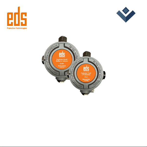
The EGMX and EGLX explosion-proof gas detectors have been developed
to continuously measure the ammable gas in the air. The EGMX model is
designed to measure the amount of methane gas in the range of 0-60% LEL.
The EGLX model is designed to measure the amount of LPG in the range of
0-60% LEL. EGX gas detectors are compatible with EGP series panels. Eight
explosion-proof gas detectors are connected to control panel directly. If more
connection required 4-20mA input module must be used.
Gas Detection Product Range
DESCRIPTION
Code Explanation
EGMX Explosion Proof Methane Detector
EGLX Explosion Proof LPG Detector
EGP1 Addressable Gas Control Panel 1 Loop
EGP2 Addressable Gas Control Panel 2 Loop
EGP3 Addressable Gas Control Panel 3 Loop
EGP4 Addressable Gas Control Panel 4 Loop
EGLC Gas Control Panel Loop Card
EGC Addressable Carbon Monoxide Detector
EGCN2 Addressable Carbon Monoxide and Nitrogen Dioxide Detector
EGN2 Addressable Nitrogen Dioxide Detector

4
EGN Addressable Nitrogen Oxide Detector
EGOS Addressable External Siren
EGLS Addressable Loop Siren
EGR Addressable Relay
EGIM Addressable 4-20mA Input Module

5
2TECHNICAL DRAWING

6
TECHNICAL SPECIFICATIONS
3
Model EGLX EGMX
Environmental class Outdoor
Electrical
Nominal voltage 4-20mA/RS485(Optional)
Supply voltage range 19 – 28V DC
Stand-by current <32mA(24VDC)
LED indicator
Yellow Fault
Green Operation
Sensor
Sensor type Catalytic
Detection gases LPG Methane
Detection range 0-60% LEL
Measurement unit LEL
Response time <10 s
Sensor life 5 year
Repeatability %2
Calibration Factory calibration
Recommended calibration time 1 year

7
General
Housing material Aluminium pressure die-casting
Housing shape Standard
Extrenal cover color Gray
Protection class IP68
Nominal power consumption <1W
Operating humidity 15 to 90%RH
Operating temperature -10 C / +50° C
Storage temperature 0° C / +20°C
Storage life 1 year
Storage pressure 800 - 1200 mbar
Dimension (HxWxD) 120x125x85mm
Weight 1,136g
Production year The rst 2 digits of the serial number on the product indicate
the production date (The number on the label of the product).
Producer EDS Elektronik Destek Sanayi ve Ticaret Ltd.
Meclis Mah. Teraziler Cad. Hayran Sk. No: 4 34785
Sancaktepe / İstanbul / Turkey
Recycling

4
This section describes the detector mounting. Please do not start the
mounting process without understanding the system, its parts and the
working principle of the system.
It is recommended to start the assembly after reading the warnings and
points to be considered.
WARNING
Anti-static measures should be taken before touching electronic materials.
Installation and maintenance must be done by authorized personnel.
Errors that may cause damage after an intervention to the device without
reading the entire user manual may exclude the device from the warranty.
Wall Mounting
First, open the detector cover.
Do the wiring of the places where 20mm cable glands will be installed.
Find the 2 mounting locations indicated by A shown in gure 1.
8
MOUNTING AND CABLING
A
A
Figure 1: Mounting Location

Figure 2: Mounting Height
LPG
Detector
15-25cm
Choose a clean and smooth wall at eye level.
Be careful to install it in an area where there is no air ow, no fans and no
vibration.
It is not recommended to be installed close to radio frequency devices.
Make sure that it is installed in a suitable area for calibration and
maintenance.
For detector mounting, mount it from the necessary places using
M3x30mm screw and Ø 6mm plastic socket.
It is recommended to mount the LPG detector at 15-25cm and methane
detector at 0-10cm (Figure 2).
9
Methane
Detector 0-10cm

10
Cabling
Labels and cable functions should be stated in the cablings made.
A proper cabling should be supplied for electrical terminals.
You can reeve the cables from the holes in the lower box for 4-20mA
cabling
and Relay cabling.
8 connections can be made to control panel directly to the control panel.
If more connection is required 4-20mA input module must be used.
Cable Properties
The cable to be connected between detector and panel should have 1.5mm2
horizontal cutting at minimum and absolutely include ground cable. For
each connection, maximum cable length should be 400m.
Recommended cable: 18 AWG three conductor, insulated, stranded,
shielded copper cable

11
2
3
1 1
11
1
2
3
Wall Mounting Place
20M Cable Gland Connection
Sensor Place
4
5
6
Panel Connection
Sensor Connection
Power Error LED
Figure 3 : Gas Detector Illustration
Figure 4 : Gas Detector Connection
Electrical Connection
Detector connections are as shown in Figure 3.
3
4
2
2
1
3
4
5
6

12 Figure 5 : Control Panel Detector Connections
Control Panel Detector Connections
The connection between the detector and the control panel is made according
to Figure 5.

Figure 5 : Control Panel Detector Connections Figure 6 : Detector to 4-20mA Input Module Connection Scheme
Detector to 4-20mA Input Module Connection
Detectors can be connected to the control panel via 4-20mA input module
from IN connections. INX to IOUT, 24V to +V and GND to GND connection
must be made.
For 4-20mA connection please refer to EGP control panel user manual.
13
24V
GND
SIGN
G.IN
SIGN
G.OUT
GND
IN8
IN7
IN6
IN5
N4
IN3
IN2
IN1
V+
GND
V+

14
Power up the detector.
Make the necessary output connections.
Plug the detector to the control panel.
You can see your data after making detector cable connections to the
control panel.
In normal operation, the green LED lights.
The yellow LED lights during error.
FIRST OPERATION
56

Errors in the detector are shown at the control panel.
In case of error, the yellow LED on the detector ashes continuously.
If there is a communication error, the cable connections should be
checked.
Breaks in the cables may cause an error.
WARNING
Make sure to make the connections properly.
Do not reverse charge and do not short circuit.
If there is a problem, turn off the power and contact the service.
TROUBLESHOOTING
6
15

16
RECYCLING
You could send your old devices back to our company for free recycling.
7
The above symbol indicates that this product and / or battery must not be
disposed of with household waste.
When your device has reached the end of its useful life, contact your local
authority for disposal and recycling options, take it to a collection point for the
recycling of electrical and electronic equipment or hand it over to EDS Elektronik.
This product does not contain harmful or prohibited substances specied in the
Regulation on the Control of Waste Electrical and Electronic Equipment issued by
the Turkish Republic Ministry of Environment and Urbanization.
Complies with WEEE regulations.
European Union
The above symbol means that your product and / or battery must be disposed of
separately from household waste in accordance with local laws and regulations.
When this product has reached the end of its useful life, hand it in at the collection
point indicated by your local authority. The separate collection and recycling of
your product and / or battery at the time of disposal will help to conserve natural
resources and ensure that it is recycled in a manner that protects human health
and the environment
8

RECYCLING WARRANTY CERTIFICATE
8
The terms of the warranty is valid for products sold in Europe Union.
Failure to occur during loading, unloading and shipment after delivery of
the goods is not covered by the warranty.
Damage, malfunction and information services caused by operating
errors are not covered by the warranty.
Damage and malfunctions due to low or high voltage, faulty electrical
installation, voltage other than the voltage indicated on the product label are
not covered by the warranty.
Failures and damages resulting from natural disasters (earthquake, ood,
etc.), re and lightning are not covered by the warranty.
The warranty is void if the document is tampered with and the original
serial number is removed.
Warranty Conditions
1. The warranty period starts from the delivery date of the product and is for
1 year.
2. The product is completely under the warranty scope of our company
including all the pieces.
3. In case of the product’s breaking down within the warranty period, so the
repair period is added to the warranty period. The maximum repair period of
the product is 20 working days.
17

This period starts from the notification date of the product’s failure to the
service station and in default of the service station, so one of those as the
product’s seller, dealer, agent, representation,importer or importer-produ-
cer. If the product is not troubleshot with in 10 days, the importer-producer
or importer must assign another product within similar properties to the
use of the consumer till the product’s repair is completed.
4. In case of the product’s breaking down within the warranty period either
due to material and labor or mounting failures; then the repair shall be
made without requesting any charge as labor cost, shanged part fee or
under any name.
5. Despite the consumer uses the repair right;
5.1. Since the product is delivered to the consumer and provided that being
within the warranty period,
if the same failure repeats more than 2, or the different failures occur more
than 4, or the total elements of the different failures exceed 6 times with in
the specified warranty period in 1 year, as well as these failures perpetuate
not to benefit from the product,
5.2. If the maximum period required to repair is exceeded,
5.3. In the situations of the determination that the failure’s repair is im-
possible with a report to be issued by the firm’s service station and in the
unavailability of the firm’s service station, respectively by one of the seller,
dealer, agent, representation, importer or importer-producer; the consumer
can request the free change of the product, refund or price discount at
defectionrate.
18

Producer
Stamp / Signature:
THIS CERTIFICATE HAS BEEN ISSUED UPON THE PREMISSON OF THE DIRECTORATE
GENERAL OF CONSUMER PROTECTION AND MARKET SURVEILLANCE OF THE
MINISTRY OF CUSTOMS AND TRADE WITH NUMBER 4077.
Manufacturer title / Service address:
EDS Elektronik Destek San. ve Tic. Ltd. Şti.
Meclis Mah. Teraziler Cad. Hayran Sok.
No:4 34785
Sancaktepe/Istanbul/Turkey
Tel: 0216 528 45 00 Fax: 0216 314 17 80
6. The failures arising from the use of the product contrary to the particulars in
the user’s manual are outside the scope of warranty.
7. For the problems to be arisen regarding the Warranty Certicate, you can apply
to the Directorate-General of Consumer Protection and Market Surveillance of
the Ministry of Customs and Trade.
19
PRODUCT INFORMATION
Type of product : Explosion - Proof Gas Detectors
Brand : EDS
Model : EGMX & EGLX
Serial no and bandrol :
Warranty period : 1 year
Maximum repair time : 20 days
Product life time : 5 years
Delivery date and place:

EGMX-EGLX-UM-2238-R0
EDS Elektronik Destek San.ve Tic. Ltd. Şti.
Meclis Mah. Teraziler Cad. Hayran sk. No:4 34785
Sancaktepe /İstanbul /Turkey
This manual suits for next models
2
Table of contents
Other EDS Gas Detector manuals
Popular Gas Detector manuals by other brands

BW Technologies
BW Technologies GasAlertMicro 5 Quick reference guide

Critical Environment Technologies
Critical Environment Technologies LPT-M Operation manual

AIR SYSTEMS
AIR SYSTEMS CO-91 Series Calibration guide

Riken Keiki
Riken Keiki SD-1D operating manual

Teledyne
Teledyne OLCT 10 N user manual

SENKO
SENKO SP-MGTP user manual