Edwards Drystar GV80-EH250 User manual

A505-59-880
Issue B Original
Instruction Manual
Drystar® GV80/160/250/400-EH250/500A Booster
Connection Kits and GV160-EH1200 Booster Connection Kits
Description Item Number
GV80-EH250 Booster Connection Kit A505-59-000
GV80-EH500A Booster Connection Kit A505-60-000
GV160-EH250 Booster Connection Kit NCD-086-000
GV160-EH500A Booster Connection Kit NCD-087-000
GV160-EH1200 Booster Connection Kit NCD-088-000
GV250/400-EH250 Booster Connection Kit A505-70-000
GV250/400-EH500A Booster Connection Kit A505-73-000

This page has been intentionally left blank.

© Edwards Limited 2008. All rights reserved. Page i
Edwards and the Edwards logo are trademarks of Edwards Limited.
Contents
A505-59-880 Issue B
Contents
Section Page
1 Introduction .......................................................................................1
1.1 Scope and definitions ................................................................................................... 1
1.2 Description ................................................................................................................ 1
2 Technical Data ....................................................................................3
3 Installation .........................................................................................7
3.1 Safety ......................................................................................................................7
3.2 Unpack and inspect ...................................................................................................... 7
3.3 Prepare the GV pump ................................................................................................... 8
3.4 Fit an EH250/500A pump to a GV pump .............................................................................. 8
3.5 Fit an EH1200 pump to a GV160 pump ..............................................................................11
3.6 Complete the installation .............................................................................................13
4 Maintenance ..................................................................................... 15
5 Storage and Disposal ........................................................................... 17
5.1 Storage ...................................................................................................................17
5.2 Disposal ...................................................................................................................17
For return of equipment, complete the HS Forms at the end of this manual.
Illustrations
Figure Page
1 Dimensions of GV80-EH250/500 combination pumping systems: refer to Table 2 ............................. 4
2 Dimensions of GV160-EH250/500/1200 combination pumping systems: refer to Table ...................... 5
3 Dimensions of GV250/400-EH250/500 combination pumping systems: refer to Table 2 ..................... 6
4 Fit an EH250/500A pump to a GV pump (GV80-EH250 combination shown) ...................................10
5 Fit an EH1200 pump to a GV160 ......................................................................................12
Edwards JP 07/09

A505-59-880 Issue B
Page ii © Edwards Limited 2008. All rights reserved.
Edwards and the Edwards logo are trademarks of Edwards Limited.
Contents
Tables
Table Page
1 Masses of combination pumping systems ............................................................................. 3
2 Checklist of components: GV80/160/250/400-EH250 Connection Kit ........................................... 7
3 Checklist of components: GV80/160/250/400-EH500A Connection Kit ......................................... 8
4 Checklist of components: GV160-EH1200 Connection Kit ......................................................... 8
Associated publications
Publication title Publication number
Vacuum pump and vacuum system safety P400-40-100

© Edwards Limited 2008. All rights reserved. Page 1
Edwards and the Edwards logo are trademarks of Edwards Limited.
Introduction
A505-59-880 Issue B
1Introduction
1.1 Scope and definitions
This manual provides installation, operation and maintenance instructions for the GV80/160/250/400-EH250/500A
Booster Connection Kits and the GV160-EH1200 Booster Connection Kit (all of which are abbreviated to Connection
Kit in the remainder of this manual). You must use the Connection Kit as specified in this manual.
Read this manual before you install the Booster Connection Kit. Important safety information is highlighted as
WARNING and CAUTION instructions; you must obey these instructions. The use of WARNINGSand CAUTIONS is defined
below.
CAUTION
Cautions are given where failure to observe the instruction could result in damage to the equipment, associated
equipment and process
The units used throughout this manual conform to the SI international system of units of measurement.
1.2 Description
Use a Connection Kit to connect an Edwards EH mechanical booster pump to a GV dry pump, to form a combination
pumping system: refer to the front cover for the Item Numbers of the Connection Kits described in this manual.
The Connection Kit contains all of the components necessary to connect the outlet of the EH pump to the inlet of the
GV pump, and (on the GV160-EH1200 Connection Kit) all of the components necessary to support the EH pump on the
GV pump.
WARNING
Warnings are given where failure to observe the instruction could result in injury or death to
people.

A505-59-880 Issue B
Page 2 © Edwards Limited 2008. All rights reserved.
Edwards and the Edwards logo are trademarks of Edwards Limited.
Introduction
© Edwards Limited 2008. All rights reserved. Page 3
Edwards and the Edwards logo are trademarks of Edwards Limited.
Technical Data
A505-59-880 Issue B
2TechnicalData
Dimensions See Figure 1
Masses See Table 1
Table 1 - Masses of combination pumping systems
EH250 EH500A EH1200
GV80 210 kg 463 lbs 230 kg 507 lbs -
GV160 295 kg 650 lbs 310 kg 683 lbs 385 kg 849 lbs
GV250 815 kg 1796 lbs 830 kg 1830 lbs -
GV400 885 kg 1951 lbs 900 kg 1984 lbs -
A505-59-880 Issue B
Page 4 © Edwards Limited 2008. All rights reserved.
Edwards and the Edwards logo are trademarks of Edwards Limited.
Technical Data
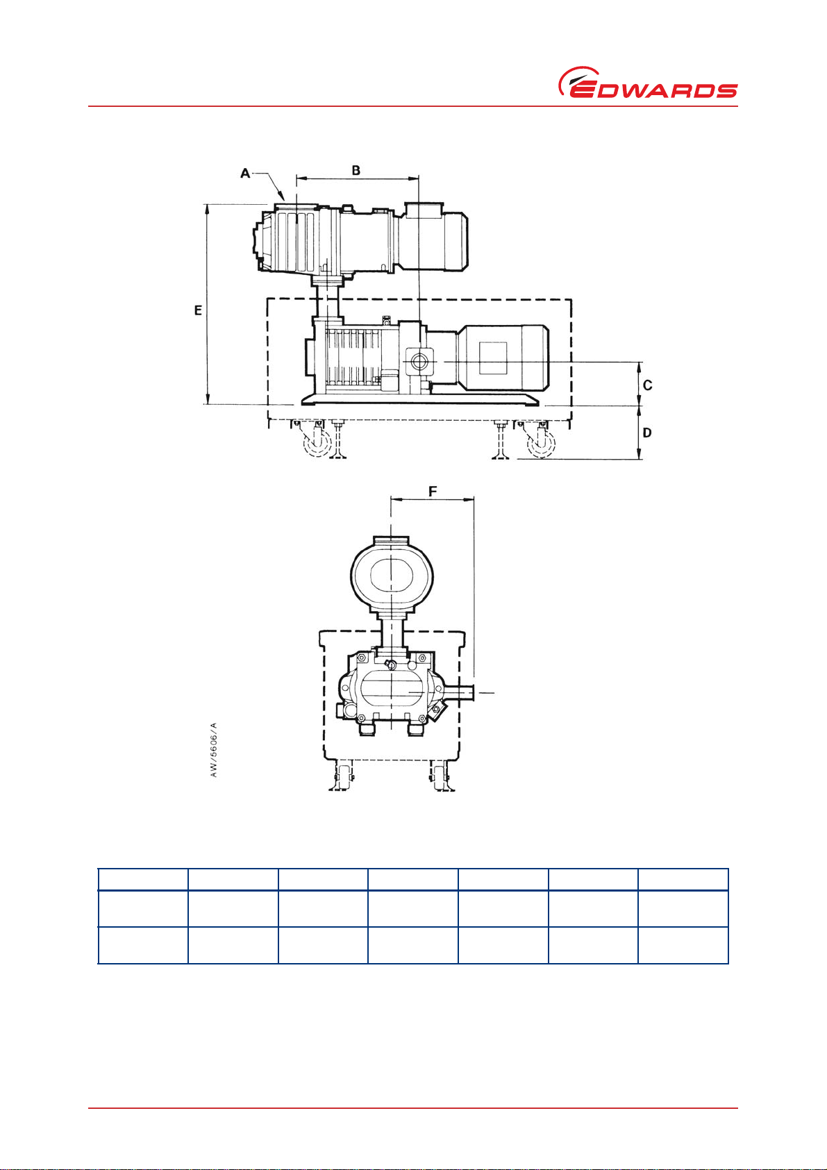
Figure 1 - Dimensions of GV80-EH250/500 combination pumping systems: refer to Table 2
ABCDEF
GV80-EH250 ISO63 399 mm
15.7 in 143 mm
5.6 in 175 mm
6.9 in 624 mm
24.6 in 270 mm
10.6 in
GV80-EH500A ISO100 301 mm
11.8 in 143 mm
5.6 in 175 mm
6.9 in 624 mm
24.6 in 270 mm
10.6 in
© Edwards Limited 2008. All rights reserved. Page 5
Edwards and the Edwards logo are trademarks of Edwards Limited.
Technical Data
A505-59-880 Issue B
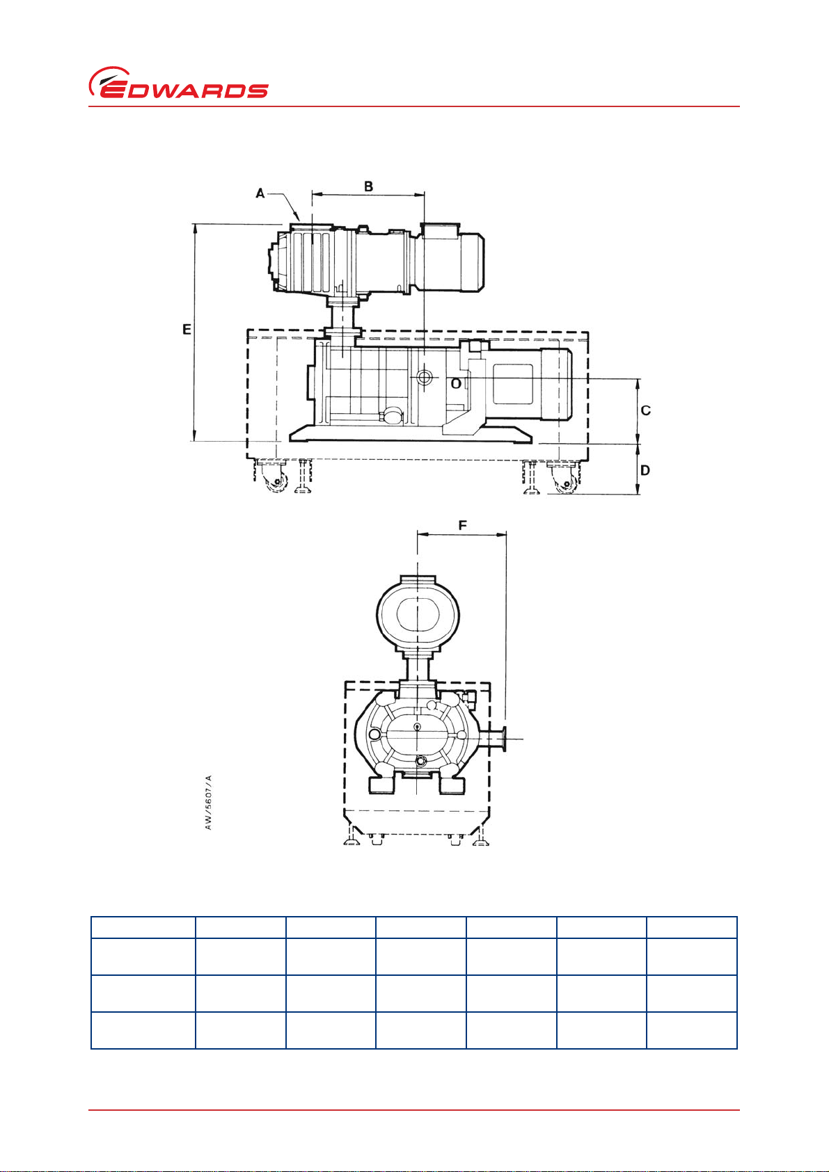
Figure 2 - Dimensions of GV160-EH250/500/1200 combination pumping systems: refer to Table
ABCDEF
GV160-EH250 ISO63 389 mm
15.3 in 197 mm
7.7 in 182 mm
7.2 in 722 mm
28.4 in 297 mm
11.7 in
GV160-EH500A ISO100 291 mm
11.4 in 197 mm
7.7 in 182 mm
7.2 in 722 mm
28.4 in 297 mm
11.7 in
GV160-EH1200 ISO160 291 mm
11.4 in 197 mm
7.7 in 182 mm
7.2 in 790 mm
31.1 in 297 mm
11.7 in
A505-59-880 Issue B
Page 6 © Edwards Limited 2008. All rights reserved.
Edwards and the Edwards logo are trademarks of Edwards Limited.
Technical Data
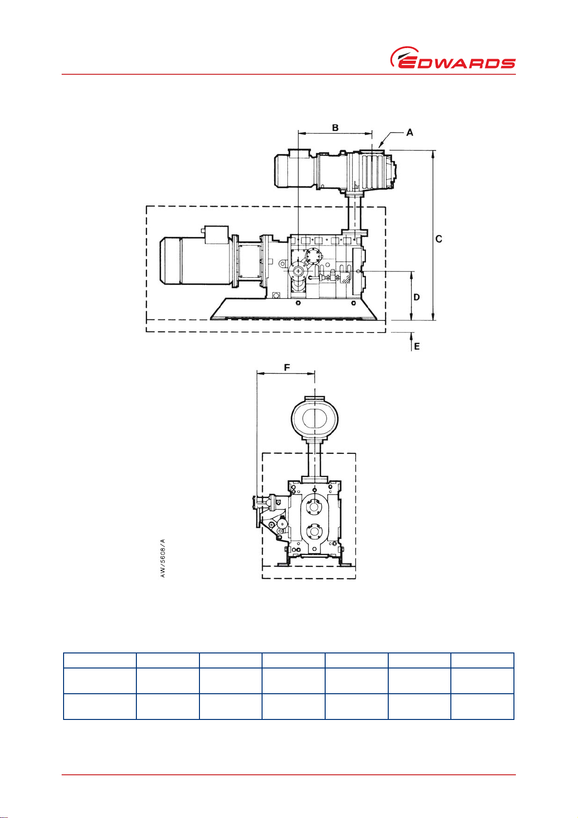
Figure 3 - Dimensions of GV250/400-EH250/500 combination pumping systems: refer to Table 2
ABCDEF
GV250/400-
EH250 ISO63 464 mm
18.3 in 996 mm
39.2 in 315 mm
12.4 in 133 mm
5.2 in 375 mm
14.8 in
GV250/400-
EH500A ISO100 366 mm
14.4 in 996 mm
39.2 in 315 mm
12.4 in 133 mm
5.2 in 375 mm
14.8 in

© Edwards Limited 2008. All rights reserved. Page 7
Edwards and the Edwards logo are trademarks of Edwards Limited.
Installation
A505-59-880 Issue B
3 Installation
3.1 Safety
A suitably trained and supervised technician must install the Connection Kit.
Ensure that the installation technician is familiar with the safety procedures which relate to the products
pumped. Wear the appropriate safety-clothing when you come into contact with contaminated components.
Dismantle and clean contaminated components inside a fume-cupboard.
If the GV pump has been in operation, vent and purge it, then switch it off and allow it to cool to a safe
temperature before you start installation.
Isolate the GV pump and other components in the process system from the electrical supply so that they
cannot be operated accidentally.
Recheck the direction of rotation of the GV pump if the electrical supply has been disconnected.
Do not reuse ‘O’ rings and Co-Seals.
Leak test the system after installation and seal any leaks found, to prevent the leakage of dangerous
substances from the system, and the leakage of air into the system.
Do not use the lifting bolts fitted to the EH mechanical booster pump to lift a GV-EH combination pumping
system.
When you refer to another instruction manual, ensure that you obey the WARNINGs and CAUTIONs in the
manual.
3.2 Unpack and inspect
Remove all packing materials and protective covers and check the Connection Kit. If any item is damaged, notify your
supplier and the carrier in writing within three days. State the Item Number of the Connection Kit, together with
your order number and your supplier’s invoice number. Do not use the Connection Kit if it is damaged.
Check that you have received the items listed in the appropriate Table 2 to 4. If any item is missing, notify your
supplier in writing within three days.
If the Connection Kit is not to be used immediately, replace any packing and protective covers and store in suitable
conditions, as described in Section 5.1.
WARNING
Obey the safety instructions given below and take note of appropriate precautions. If you do not,
you can cause injury to people and damage to equipment.
Table 2 - Checklist of components: GV80/160/250/400-EH250 Connection Kit
Qty Description Check ()
1 Flange adaptor: ISO63-ISO40
8Bolts:M8x25
8Springwashers:M8
1 ‘O’ ring: 49.5 x 3.0 mm section
A505-59-880 Issue B
Page 8 © Edwards Limited 2008. All rights reserved.
Edwards and the Edwards logo are trademarks of Edwards Limited.
Installation
3.3 Prepare the GV pump
1. If the GV pump has been in operation, vent and purge it with dry nitrogen or air, then switch it off and allow it
to cool to a safe temperature before you continue.
2. Isolate the GV pump and the other components in your process system from the electrical supply, so that they
cannot be operated accidentally.
3. If already connected, disconnect the GV inlet from your process system.
4. Ensure that the GV pump is securely bolted to the floor.
3.4 Fit an EH250/500A pump to a GV pump
Note: If your GV pump has an acoustic enclosure, the top panel(s) of the enclosure must be fitted when you fit
the EH pump.
Refer to Figure 4 and use the following procedure to fit an EH250 pump to a GV pump; where necessary, refer to the
instruction manuals supplied with the GV pump and with the EH pump.
1. Undo and remove the bolts and washers which secure the blanking plate to the inlet of the GVpump(2), then
remove the blanking-plate and the ‘O’ ring. Retain the bolts, washers and ‘O’ ring.
Table 3 - Checklist of components: GV80/160/250/400-EH500A Connection Kit
Qty Description Check ()
1 Flange adaptor: ISO63-ISO63
4Bolts:M8x25
4Springwashers:M8
1 ‘O’ ring: 78.74 x 5.33 mm section
Table 4 - Checklist of components: GV160-EH1200 Connection Kit
Qty Description Check ()
1 Flange adaptor: ISO100-ISO63
12 Bolts: M8 x 25
12 Spring washers: M8
1 ‘O’ ring: 4.38 x 0.21 inch section
1Supportplate
2Supportrods
1Stud:M12
2Bolts:M12x25
4Plainwashers:M12
2Springwashers:M12
2Nuts:M12
WARNING
Ensure that the GV pump is secured to the floor before you fit the Connection Kit. If you do not,
the GV pump may move when you fit the EH pump, and the EH pump may fall.

© Edwards Limited 2008. All rights reserved. Page 9
Edwards and the Edwards logo are trademarks of Edwards Limited.
Installation
A505-59-880 Issue B
2. Use suitable lifting equipment to raise theEHpump(1) over theGVpump(2): refer to the EH pump instruction
manual.
3. Refer to detail B. Wipe clean the sealing faces of the adaptor flange (8), the inlet (6) of the GV pump, and the
outlet (9) of the EH pump.
4. Secure the adaptor flange (8) to the inlet (6) of the GV pump:
For an EH250 pump, use four of theM8x 25 bolts and spring washers (7) supplied in the Connection Kit,
together with the plain washers and ‘O’ ring (5) removed in Step 1.
For anEH500Apump, use the bolts, plain washers and ‘O’ ring (5) removed in Step 1.
5. Fit the ‘O’ ring (3) supplied in the Connection Kit to the top face of the adaptor flange (8).
6. Carefully lower the EH pump (1) so that the pump-outlet (9) aligns with the top of the adaptor flange (8), and so
that the fixing-holes in the pump-outlet align with the fixing-holes in the adaptor flange.
7. Use the four M8 x 25 bolts and washers (4) supplied in the Connection Kit to secure the adaptor flange (8) to the
EH pump-outlet (9).
8. Continue at Section 3.6.
A505-59-880 Issue B
Page 10 © Edwards Limited 2008. All rights reserved.
Edwards and the Edwards logo are trademarks of Edwards Limited.
Installation
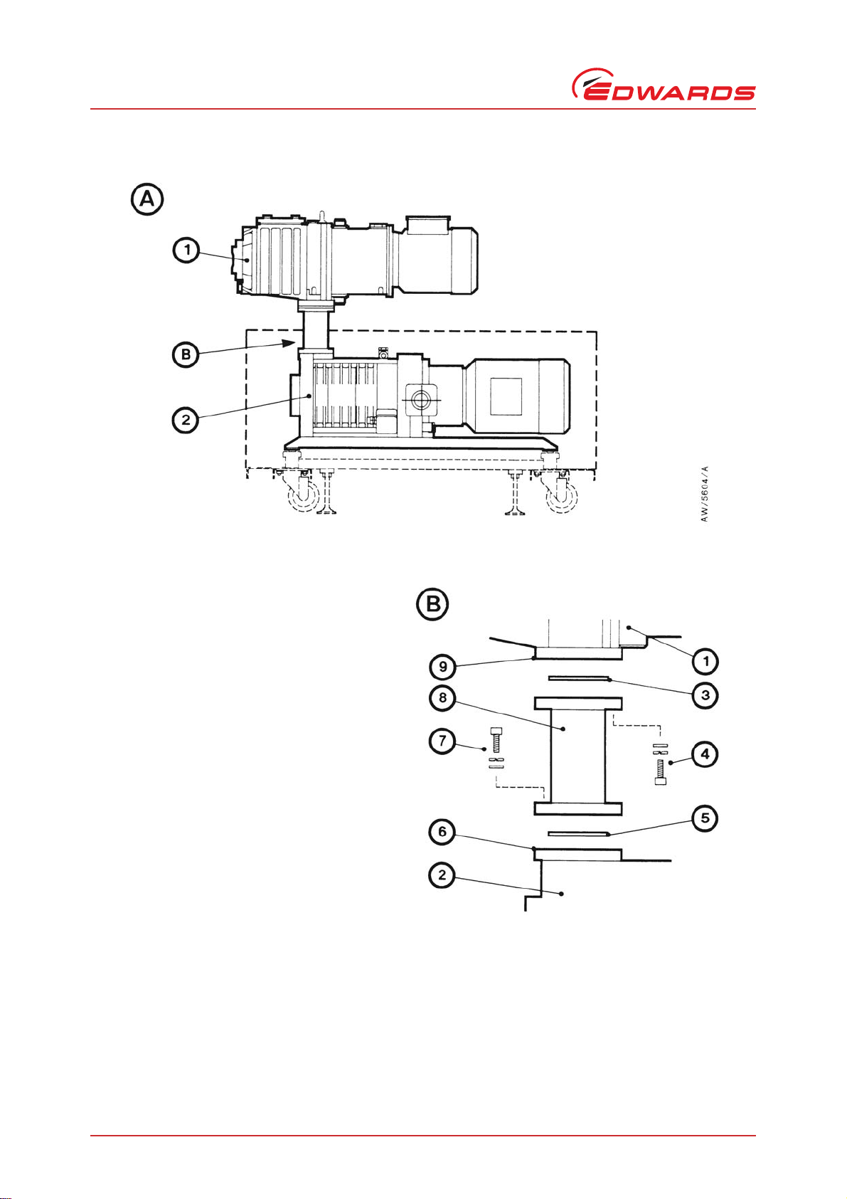
Figure 4 - Fit an EH250/500A pump to a GV pump (GV80-EH250 combination shown)
1. EH pump
2. GV pump
3. ‘O’ ring
4. Bolts, spring and plain washers
5. ‘O’ ring
6. GV pump-inlet
7. Bolts, spring and plain washers
8. Adaptor flange
9. EH pump-outlet

© Edwards Limited 2008. All rights reserved. Page 11
Edwards and the Edwards logo are trademarks of Edwards Limited.
Installation
A505-59-880 Issue B
3.5 Fit an EH1200 pump to a GV160 pump
Refer to Figure 5 and use the following procedure to fit an EH1200 pump to a GV160 pump; where necessary, refer
to the instruction manuals supplied with the GV pump and with the EH pump.
1. Use suitable lifting equipment to raise theEHpump(1) over theGVpump(3): refer to the EH pump instruction
manual.
2. Remove the top panel (2) from the GV160 enclosure, then remove the two rear lifting-bolts (if fitted) from the
GV pump (3).
3. Refer to detail C. Fit one end of the stud (11) into the M12 fixing hole in the base of the EH pump (1), then fit an
M12 nut (12) to the other end of the stud.
4. Fit the two support rods (14) to the rear lifting-bolt holes on the GV pump (3).
5. Remove the two blank grommets from the leadthrough holes in the top panel (2) of the GV enclosure, then refit
the top cover, so that the two support rods (14) pass through the leadthrough holes.
6. Fit the support plate (13) to the two support rods (14) and secure with the M12 x 25 bolts, and the plain and
spring washers (15) supplied.
7. Refer to detail B. Undo and remove the bolts and washers which secure the blanking-plate to the GV pump-inlet
(7), then remove the blanking-plate and the ‘O’ ring. Retain the plain washers and ‘O’ ring.
8. Wipe clean the sealing faces of the adaptor flange (6), the GV pump-inlet (7), and the EH pump-outlet (4).
9. Use the bolts and spring washers (9) supplied in the Connection Kit, together with the plain washers and the ‘O’
ring (8) removed in Step 7, to secure the adaptor flange (6) to the GV pump-inlet (7).
10.Fit the ‘O’ ring (10) supplied in the Connection Kit to the top of the adaptor flange (6).
11.Carefully lower the EH pump (1) so that the pump-outlet (4) aligns with the top of the adaptor flange (6), so that
the fixing-holes in the pump-outlet align with the fixing-holes in the adaptor flange, and so that the stud (11)
passes through the remaining hole in the support plate (13).
12.Adjust the M12 nut (12) on the stud (11), so that the EH pump is supported by the stud.
13.Use the four M8 x 25 bolts and washers (5) supplied in the Connection Kit to secure the adaptor flange (6) to the
EH pump-outlet (4).
14.Fit anM12nut and washer (12) to the bottom of the stud (11), to secure the stud to the support plate (13).
15.Continue at Section 3.6.
A505-59-880 Issue B
Page 12 © Edwards Limited 2008. All rights reserved.
Edwards and the Edwards logo are trademarks of Edwards Limited.
Installation
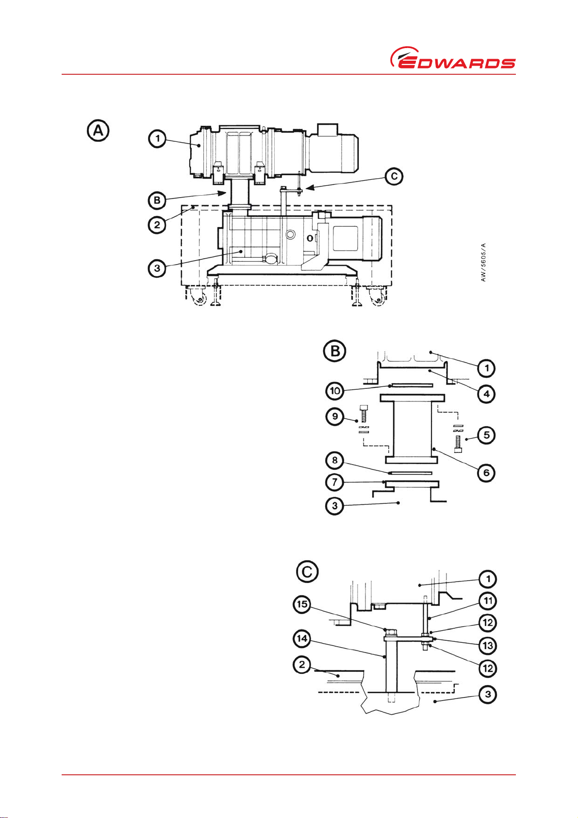
Figure 5 - Fit an EH1200 pump to a GV160
1. EH1200 pump
2. Top panel of acoustic enclosure
3. GV160 pump
4. EH pump-outlet
5. Bolts and washers
6. Adaptor flange
7. GV pump-inlet
8. ‘O’ ring
9. Bolts and washers
10.‘O’ ring
11.Stud
12.Nuts and washers
13.Support plate
14.Support rod
15.Bolts, plain and spring washers

© Edwards Limited 2008. All rights reserved. Page 13
Edwards and the Edwards logo are trademarks of Edwards Limited.
Installation
A505-59-880 Issue B
3.6 Complete the installation
1. Complete the installation of the EH pump: refer to the instruction manual supplied with the EH pump.
2. Leak test the system and seal any leaks found: refer to the GV and EH pump instruction manuals.
WARNING
Leak test the system after installation and seal any leaks found to prevent the leakage of dangerous
substances out of the system, and the leakage of air into the system.

A505-59-880 Issue B
Page 14 © Edwards Limited 2008. All rights reserved.
Edwards and the Edwards logo are trademarks of Edwards Limited.
Installation

© Edwards Limited 2008. All rights reserved. Page 15
Edwards and the Edwards logo are trademarks of Edwards Limited.
Maintenance
A505-59-880 Issue B
4Maintenance
When you maintain your GV-EH combination pumping system:
1. On a GV160-EH1200 system, ensure that the support rods, support plate and stud are securely fitted to the GV
and EH pumps. Tighten any loose nuts and bolts as necessary.
2. Inspect the adaptor flange and check that it is not damaged or corroded; if the adaptor flange is damaged or
corroded, you must replace it.
3. Check that the adaptor flange is securely fitted to the inlet of the GV pump and to the outlet of the EH pump.
Tighten any loose connection.

A505-59-880 Issue B
Page 16 © Edwards Limited 2008. All rights reserved.
Edwards and the Edwards logo are trademarks of Edwards Limited.
Maintenance
This manual suits for next models
11
Table of contents
Other Edwards Industrial Equipment manuals

Edwards
Edwards E1M40/80 Installation instructions

Edwards
Edwards Iron Worker User manual

Edwards
Edwards ELD500 Series User manual

Edwards
Edwards WRH gauge User manual

Edwards
Edwards GV250 User manual

Edwards
Edwards AIM-P-NW25 User manual

Edwards
Edwards HV8000 aftercooler Mk4 User manual

Edwards
Edwards AIM-YSL-NW25 User manual

Edwards
Edwards CDP User manual

Edwards
Edwards FL20K User manual


