Edwards AIM-YSL-NW25 User manual

D14558880
Issue H
Original Instructions
Instruction Manual
YSL Active Inverted Magnetron Gauge
Description Item Number
AIM-YSL-NW25 D14558000

This product has been manufactured under a quality management system certified to ISO 9001:2008
Declaration of Conformity
We, Edwards Limited,
Crawley Business Quarter,
Manor Royal,
Crawley,
West Sussex, RH10 9LW, UK
declare under our sole responsibility, as manufacturer and person within the EU authorised
to assemble the technical file, that the product(s)
Active Inverted Magnetron Gauge
AIM-YSL-NW25 D145-58-000
to which this declaration relates is in conformity with the following standard(s) or other
normative document(s)
EN 61326-2-3: 2013 Electrical equipment for measurement, control and laboratory
(Class B Emissions, Use. EMC requirements. Particular requirements. Test
Basic Immunity) configuration, operational conditions and performance criteria
for transducers with integrated or remote signal conditioning
EN50581: 2012 Technical Documentation for the Assessment of Electrical and
Electronic Products with respect to the Restriction of Hazardous
Substances
and fulfils all the relevant provisions of
2014/35/EU Low Voltage Directive
2014/30/EU Electromagnetic Compatibility (EMC) Directive
2011/65/EU Restriction of Certain Hazardous Substances (RoHS) Directive
Note: This declaration covers all product serial numbers from the date this Declaration was
signed onwards.
19.08.2015, Eastbourne
Mr L. Marini,
Senior
Technical Manage
r
Date and Place
P200-03-220 Issue
E
P200-10-059
Issue A
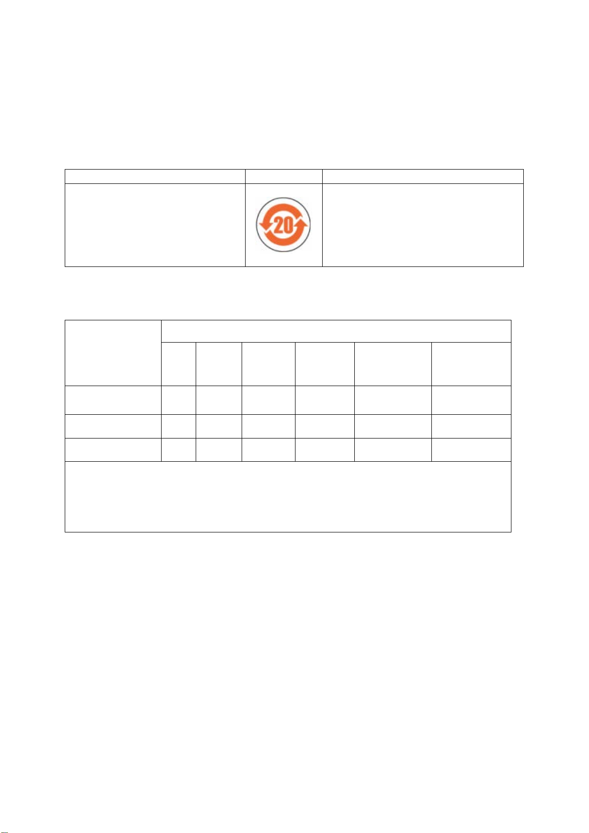
Material Declaration
In accordance with the requirements of the Chinese regulatory requirement on the Management Methods for the
Restriction of the Use of Hazardous Substances in Electrical and Electronic Products Order No. 32 (also known as
‘China RoHS2’) and SJ/T 11364 Marking for the Restricted Use of Hazardous Substances in Electronic and Electrical
Products:
Product Product Label Meaning
D14558000 AIM-YSL-NW25
This product contains hazardous substances in
at least one of the homogeneous materials
used which are above the limit requirement in
GB/T 26572 as detailed in the declaration
table below.
These parts can safely be used for the
environmental protection use period as
indicated.
材料成分声明
Materials Content Declaration
部件名称
Part name
有害物质
Hazardous Substances
铅
Lead
(Pb)
汞
Mercury
(Hg)
镉
Cadmium
(Cd)
六价铬
Hexavalent
Chromium
(Cr VI)
多溴联苯
Polybrominated
biphenyls (PBB)
多溴二苯醚
Polybrominated
diphenyl ethers
(PBDE)
印刷电路组件
(PCA)
Printed Circuit
Assembly (PCA)
X O X O O O
电缆/电线/连接器
Cable/wire/connector
X O O O O O
机械部件
Mechanical Components
X O O O O O
O: 表示该有害物质在该部件的所有均质材料中的含量低于 GB/T 26572 标准规定的限量要求。
O: Indicates that the hazardous substance contained in all of the homogeneous materials for this part is
below the limit requirement in GB/T 26572.
X: 表示该有害物质在该部件的至少一种均质材料中的含量超出 GB/T26572 标准规定的限量要求。
X: Indicates that the hazardous substance contained in at least one of the homogeneous materials used for
this part is above the limit requirement of GB/T26572.
NOTE: These products are EU RoHS compliant, the following Exemptions apply:
6(b)
Lead
as an alloying element in aluminium containing up to 0.4% by weight
6(c) Copper alloy containing up to 4%
lead
by weight
7(a)
Lead
in in high melting temperature type solder (i.e. lead based alloys containing 85% by or more)
7(b)
Lead
in solders for servers, storage and storage array systems, network infrastructure equipment for switching, signalling,
transmission, and network management for telecommunications
7(c) I Electrical and electronic components containing
lead
in a glass or ceramic other than dielectric ceramic in capacitors, e.g.
piezoelectronic devices, or in a glass or ceramic matrix compound
7(c) II
Lead
in dielectric ceramic in capacitors for a rated voltage of 125 V AC or 250 V DC or higher
8(b)
Cadmium
and its compounds in electrical contacts
15
Lead
in solders to complete a viable electrical connection between semiconductor die and carrier within integrated circuit flip
chip packages
34
Lead
in cermet-based trimmer potentiometer elements

This page has been intentionally left blank.

© Edwards Limited 2020. All rights reserved. Page i
Edwards and the Edwards logo are trademarks of Edwards Limited.
Contents
D14558880 Issue H
Contents
Section Page
1 INTRODUCTION .................................................................................... 1
1.1 Scope ...................................................................................................................... 1
1.2 Description ................................................................................................................ 1
1.3 Gas Dependency ......................................................................................................... 2
2 TECHNICAL DATA ................................................................................. 3
2.1 Mechanical Data ......................................................................................................... 3
2.2 Performance, Operating and Storage Conditions ................................................................... 3
2.3 Electrical Data ........................................................................................................... 4
2.4 Materials Exposed to Vacuum. ......................................................................................... 4
3 INSTALLATION ..................................................................................... 5
3.1 Unpack and Inspects ..................................................................................................... 5
3.2 Fit the AIM Gauge to the Vacuum System ............................................................................ 5
3.3 Electrical Connections .................................................................................................. 5
3.3.1 Connect To Edwards Controllers or AGD Display .................................................................... 6
3.3.2 Connect To Your Own Supply and Control Equipment ............................................................. 6
4 OPERATION ........................................................................................ 9
4.1 Safety ...................................................................................................................... 9
4.2 Enable and Disable the AIM Gauge .................................................................................... 9
4.3 Pressure Measurement .................................................................................................. 9
4.4 Error Output Signal .....................................................................................................10
5 MAINTENANCE ................................................................................... 11
5.1 Introduction .............................................................................................................11
5.2 Replace the Body Tube ................................................................................................11
5.2.1 Remove the AIM Gauge from the Vacuum System .................................................................11
5.2.2 Fit the New Body Tube .................................................................................................11
5.2.3 Refit the AIM Gauge To the Vacuum System ........................................................................11
5.3 Replace the Electrode Assembly .....................................................................................11
5.4 Replacing the Electronics and Magnet Housing ....................................................................13
5.5 Clean the internal components ....................................................................................... 13
5.6 Fault Finding .............................................................................................................13
6 STORAGE AND DISPOSAL ....................................................................... 15
6.1 Storage ...................................................................................................................15
6.2 Disposal ...................................................................................................................15
6.3 Return the equipment or components for service..................................................................15
7 SPARES AND ACCESSORIES ..................................................................... 17
7.1 Introduction .............................................................................................................17
7.2 Spares .....................................................................................................................17
7.3 Accessories ...............................................................................................................17
GEC/ 2020-AVI-GCN-0011

D14558880 Issue H
Page ii © Edwards Limited 2020. All rights reserved.
Edwards and the Edwards logo are trademarks of Edwards Limited.
Contents
Illustrations
Figure Page
1 General View of the AIM Gauge (showing NW25 flange) ........................................................... 2
2 Dimensions (mm) ........................................................................................................ 3
3 Schematic Diagram of Typical Electrical Connections ............................................................. 7
4 Exploded View of the AIM Gauge .....................................................................................12
Tables
Table Page
1 Pins On the AIM Gauge Electrical Connector Socket ............................................................... 6
2 Pressure and Voltage Characteristics for Nitrogen and Dry Air ..................................................10
Associated publications
Publication title Publication number
Vacuum pump and vacuum system safety P40040100
Trademark credits
Fomblin® is a registered trademark of Ausimont SpA.
LET-LOK® is a registered trademark of HAM-LET Group.
Swagelok™ is trademark of Crawford Fitting Company.
Viton™ is trademark of DuPont Dow Elastomers L.L.C.

© Edwards Limited 2020. All rights reserved. Page 1
Edwards and the Edwards logo are trademarks of Edwards Limited.
INTRODUCTION
D14558880 Issue H
1 INTRODUCTION
1.1 Scope
This manual provides installation, operation and maintenance instructions for the Edwards AIM Gauge (Active
Inverted Magnetron Gauge). You must use the AIM Gauge as specified in this manual.
Important safety information is highlighted as WARNING and/or CAUTION instructions which must be followed. The
use of WARNINGS and/or CAUTIONS is defined below.
CAUTION
Cautions are given where failure to observe the instruction could result in damage to the equipment, associated
equipment and process.
The units used throughout this manual conform to SI international system of measurement followed by imperial units
in parenthesis; SI (imperial).
The following warning symbols are on the pump:
1.2 Description
The AIM Gauge, shown in Figure 1, is an inverted magnetron gauge head and gauge controller in a single compact
unit. The gauge operates as a cold cathode ionisation gauge, in which the pressure is measured indirectly as a
function of the current which flows in a Townsend discharge maintained in the body tube.
The measurement range of the AIM Gauge is 1 x 10⁻⁸ to 1 x 10⁻² mbar. The AIM Gauge vacuum connection is an NW25
flange.
The AIM Gauge requires a 13.5 to 6 V d.c. Power supply; it has a 2 to 10 V d.c. analogue output which is related to
pressure. The AIM Gauge is compatible with all of the Edwards AGCs (Active Gauge Controllers) and with the
appropriate versions of the Edwards AGDs (Active Gauge Displays). Alternatively, you can use an independent power
supply for the AIM Gauge output signal with a voltmeter or an analogue-to-digital converter.
We recommend that you do not operate the AIM Gauge unless the pressure in the vacuum system is 1 x 10⁻² mbar or
lower. A gauge enable signal is used to control the operation of the AIM Gauge; refer to Section 4.2 for more
information.
An 8-way electrical connector socket on the AIM Gauge (Figure 1, item 6) is used to connect the AIM Gauge to your
AGC, AGD or electrical supply and voltmeter. Electrical cables fitted with suitable connector plugs are available as
accessories.
A gauge identification signal is available on the electrical connector; this signal is used by Edwards AGCs to identify
which type of Active Gauge is connected.
The AIM Gauge has self-monitoring fault detection circuits. When these circuits detect that the AIM Gauge is not
operating correctly, an error signal is set; this error signal is available on the electrical connector. The device which
WARNING
Warnings are given where failure to observe the instruction could result in injury or death to
people.
Warning - refer to accompanying
documentation. Warning - risk of electric shock.

D14558880 Issue H
Page 2 © Edwards Limited 2020. All rights reserved.
Edwards and the Edwards logo are trademarks of Edwards Limited.
INTRODUCTION
sets the error signal is an FET transistor which acts like a switch. When no error is detected, the output of the
transistor is on (closed or low impedance). When the fault detection circuits detect an error, the transistor output
changes to off (open or high impedance).
Note: If you use an Edwards AGC controller or AGD display, the AIM Gauge error signal is not used.
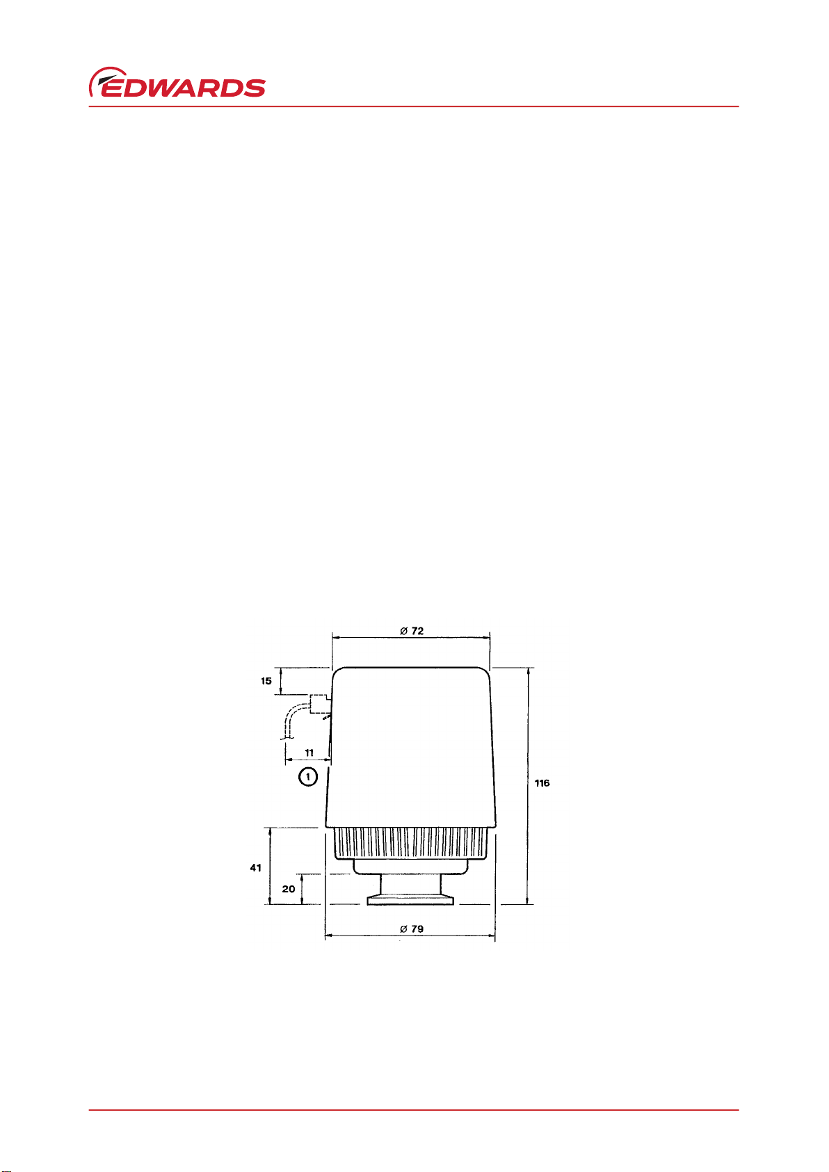
Figure 1 - General View of the AIM Gauge (showing NW25 flange)
1.3 Gas Dependency
The ionisation of the gas in the vacuum system is dependent on both the pressure and the physical properties of the
gas. Therefore, the output signal of the AIM Gauge is gas dependent.
The output signal voltage to pressure conversions in Table 2 apply for nitrogen and dry air.
Calibration graphs for use with argon, neon, krypton, helium and carbon dioxide are available on request; contact
your supplier or Edwards.
KEY
1 End cap 2 Vacuum flange
3 Body tube 4 Magnet housing
5 Cable connector plug 6 AIM gauge connector socket
© Edwards Limited 2020. All rights reserved. Page 3
Edwards and the Edwards logo are trademarks of Edwards Limited.
TECHNICAL DATA
D14558880 Issue H
2 TECHNICAL DATA
2.1 Mechanical Data
2.2 Performance, Operating and Storage Conditions
Figure 2 - Dimensions (mm)
Dimensions See Figure 2
Mass 860 g
Volume of gauge tube 26 cm3
Enclosure rating IP403
Ambient temperature
Operation 5 to 60°C
Storage 0 to 70°C
Ambient humidity (operation) 10 to 90% (non-condensing)
Maximum operating altitude 2000m
Maximum internal pressure 10 bar absolute (9 bar gauge)
Pressure measurement range 1 x 10⁻⁸ to 1 x 10⁻² mbar
Pollution category 1 x 10⁻⁸ to 1 x 10⁻² mbar
KEY
1 Clearance required for electrical cable

D14558880 Issue H
Page 4 © Edwards Limited 2020. All rights reserved.
Edwards and the Edwards logo are trademarks of Edwards Limited.
TECHNICAL DATA
2.3 Electrical Data
2.4 Materials Exposed to Vacuum
Electrical supply
Voltage +13.5 to +36 V d.c.
Max voltage ripple 1 V peak to peak
Max source resistance 50 W
Maximum power consumption 3.5 W
Electrical connector FCC68/RJ45 type, 8-way
Pressure output signal
Range 2 < output < 10 V d.c.
Error range output < 2 V d.c. or
output > 10 V d.c.
Impedance 0.1 W
Min load impedance 10 kW
Max current source 1 mA
Gauge enable
Control sense Active low
Active level < 1.3 V
Control impedance 12 kW pull-up to positive supply
Error output
External load rating 40 V d.c., 100 mA max
Back EMF suppression diode*
Min. surge rating 1 A
Min. reverse voltage rating 100 V
Gauge identification resistance 100 kW ± 2%
Stainless steel (AISI 304 and 306)
Fluoroelastomer
Soda lime glass

© Edwards Limited 2020. All rights reserved. Page 5
Edwards and the Edwards logo are trademarks of Edwards Limited.
INSTALLATION
D14558880 Issue H
3 INSTALLATION
3.1 Unpack and Inspect
Remove all packing materials and protective covers and check the AIM Gauge for damage.
If the AIM Gauge is damaged, notify your supplier and the carrier in writing within three days; state the Item Number
of the AIM Gauge together with your order number and your supplier’s invoice number. Retain all packing materials
for inspection. Do not use the AIM Gauge if it is damaged.
If the AIM Gauge is not to be used immediately, replace the protective covers. Store the AIM Gauge in suitable
conditions as described in Section 6.
3.2 Fit the AIM Gauge to the Vacuum System
The AIM Gauge can be mounted in any orientation. To avoid the build- up of debris or condensable material in the
body tube of the AIM Gauge (which will probably cause pressure measurement errors), we recommend that you install
the AIM gauge vertically as shown in Figure 2.
Use an ‘O’ ring / centring ring or Co-Seal and clamp to connect the NW25 flange of the AIM Gauge to a similar flange
on your vacuum system.
If required, you can turn the end-cap (relative to the magnet housing) so that the electrical connection socket is in
a convenient position on your system; refer to Figure 1 and use the following procedure: hold the magnet housing (4)
and turn the end-cap (1) in a clockwise or anticlockwise direction (arrow B) until the electrical connection socket (6)
is in the required position.
3.3 Electrical Connections
When using a cable longer than 30 m, full compliance with European Standards requires an in-line surge suppressor
(please refer to Section 7.3).
WARNING
The AIM gauge incorporates magnets. Keep away from heart pacemakers, computers, credit cards
and any other magnetically sensitive devices.
WARNING
Magnetic Field may interfere with pacemakers. Maintain a distance of minimum 10 cm between
the magnet and the heart pacemaker. You can also use anti-magnetic shield to prevent the
influence of strong magnetic field.
WARNING
If the AIM Gauge malfunctions, the AIM Gauge pressure output may be incorrect. If such a failure
could cause injury to people or damage equipment, you must install a suitable control system to
indicate the failure and, if necessary, to close down your process system.

D14558880 Issue H
Page 6 © Edwards Limited 2020. All rights reserved.
Edwards and the Edwards logo are trademarks of Edwards Limited.
INSTALLATION
3.3.1 Connect To Edwards Controllers or AGD Display
Connect the AIM Gauge to the controller or display with a cable which is terminated in suitable connectors. Suitable
cables are available from Edwards (refer to Section 7).
3.3.2 Connect To Your Own Supply and Control Equipment
Note: Do not connect the electrical supply common (pin 2) to the signal common (pin 5). If you do, the AIM Gauge
pressure output signal will be inaccurate.
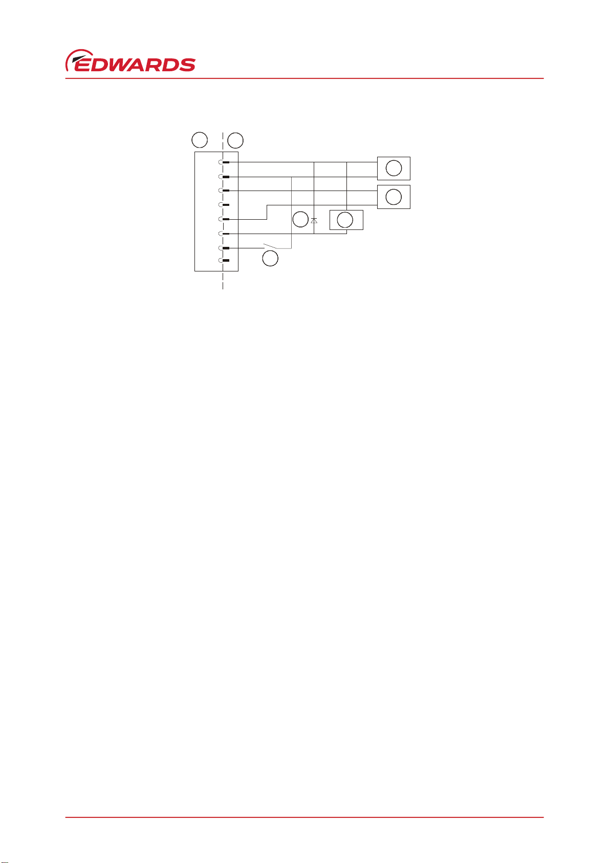
A schematic diagram of the recommended electrical connections to the AIM Gauge is shown in Figure 3.
The pins on the AIM Gauge electrical connection socket are used as shown in Table 1. The specification of the
electrical supply, d.c. relay and back EMF suppression diode are given in Section 2.
The connection to pin 6 is optional. Make the connection to pin 6 if you want to connect the error signal to a d.c.
relay: you must connect a suppression diode between pins 1 and 6 to protect the AIM Gauge from transient voltages
generated when the d.c. relay is switched off.
Connect a switch between pins 2 and 7 to enable and disable the gauge (refer to Section 4.2). If you want to measure
the gauge identification signal (which identifies the AIM Gauge), measure the resistance between pins 4 and 5.
Table 1 - Pins On the AIM Gauge Electrical Connector Socket
Pin
Number Use
1 Electrical supply positive voltage
2 Electrical supply common
3 Pressure measurement output signal
4 Gauge identification signal
5 Signal common
6 Error output signal
7 Gauge enable
8 No connection
© Edwards Limited 2020. All rights reserved. Page 7
Edwards and the Edwards logo are trademarks of Edwards Limited.
INSTALLATION
D14558880 Issue H
Figure 3 - Schematic Diagram of Typical Electrical Connections
KEY
1 AIM Gauge electrical connector socket 2 Cable electrical connector plug
3 Electrical supply 4 Voltmeter
5 D.C. relay (optional) 6 Back EMF suppression diode (optional)
7 Gauge enable switch
1
2
3
4
5
6
7
8
12
3
4
5
6
7
+
0V
+
0V

D14558880 Issue H
Page 8 © Edwards Limited 2020. All rights reserved.
Edwards and the Edwards logo are trademarks of Edwards Limited.
INSTALLATION

© Edwards Limited 2020. All rights reserved. Page 9
Edwards and the Edwards logo are trademarks of Edwards Limited.
OPERATION
D14558880 Issue H
4 OPERATION
4.1 Safety
4.2 Enable and Disable the AIM Gauge
CAUTION
Do not operate the AIM Gauge for long periods when the system pressure is above 1 x 10⁻² mbar. If you do, the
anode pin can be damaged and the AIM Gauge can be severely contaminated.
We recommend that you only enable the gauge when the system pressure is lower than 1 x 10⁻² mbar and that you
disable the gauge when the system pressure is 1 x 10⁻² mbar or higher.
If you have connected the AIM Gauge to an AGC or AGD, refer to the corresponding instruction manual for details of
how to enable (switch on) and disable (switch off) the AIM Gauge.
Otherwise, to enable (switch on) the AIM Gauge, connect pin 7 to pin 2 (or to ground). To disable (switch off) the AIM
Gauge, disconnect pin 7 from pin 2 (or from ground).
4.3 Pressure Measurement
If you connected the AIM Gauge to an Edwards AGC controller or AGD display, the pressure measured by the AIM
Gauge is shown on the display.
If you connected the signal output of the AIM Gauge to a voltmeter, convert the measured voltage to the
corresponding pressure value: refer to Table 2.
If necessary, adjust the pressure reading to compensate for the RMM of the gas in your vacuum system (refer to
Section 1.3).
Generally Magnetron gauges exhibit a delay between switching on and establishment of the discharge. This striking
time increases with decreasing pressure. Typical values for a clean gauge are shown below.
Less than 20 seconds at pressures higher than 10-7 mbar
Less than 2 minutes at 10-8 mbar
WARNING
Do not use the AIM Gauge to measure the pressure of explosive or flammable gases or mixtures.
WARNING
Never operate the AIM Gauge when it is disconnected from the vacuum system or when there are
explosive or flammable gases in the surrounding atmosphere or the vacuum system. High voltages
(up to 3kV) are generated inside the body tube of the AIM Gauge; these could cause injury to
people or could be a source of ignition.
WARNING
The AIM gauge incorporates magnets. Keep away from heart pacemakers, computers, credit cards
and any other magnetically sensitive devices.

D14558880 Issue H
Page 10 © Edwards Limited 2020. All rights reserved.
Edwards and the Edwards logo are trademarks of Edwards Limited.
OPERATION
4.4 Error Output Signal
Note: The error signal output is not used if you connect the AIM Gauge to an Edwards AGC controller or AGD
display.
The error output signal indicates when the AIM Gauge is operating correctly. If required, you can use the error output
signal to control the operation of your vacuum system. The signal is open (that is, the output of the FET transistor is
off):
For 1.5 seconds after the AIM Gauge is switched on.
When the pressure output signal is out of range, that is the signal is < 1.5 V or > 10.7 V.
When the discharge from the AIM Gauge has failed to strike (ignite); that is, if the voltage after switch-on
fails to rise above 2.5 V.
Table 2 - Pressure and Voltage Characteristics for Nitrogen and Dry Air
Pressure (mbar) Output voltage (V) Pressure (torr)
1.0 x 10⁻⁸
2.4 x 10⁻⁸
5.8 x 10⁻⁸
8.2 x 10⁻⁸
1.2 x 10⁻⁷
2.00
2.50
3.00
3.20
3.40
7.5 x 10⁻⁹
1.8 x 10⁻⁸
4.3 x 10⁻⁸
6.1 x 10⁻⁸
8.7 x 10⁻⁸
1.6 x 10⁻⁷
2.3 x 10⁻⁷
3.2 x 10⁻⁷
4.4 x 10⁻⁷
5.9 x 10⁻⁷
3.60
3.80
4.00
4.20
4.40
1.2 x 10⁻⁷
1.7 x 10⁻⁷
2.4 x 10⁻⁷
3.3 x 10⁻⁷
4.5 x 10⁻⁷
7.9 x 10⁻⁷
1.0 x 10⁻⁶
1.3 x 10⁻⁶
1.6 x 10⁻⁶
2.0 x 10⁻⁶
2.5 x 10⁻⁶
3.1 x 10⁻⁶
3.9 x 10⁻⁶
4.9 x 10⁻⁶
6.1 x 10⁻⁶
4 .60
4.80
5.0 0
5.20
5.40
5.60
5.80
6.00
6.20
6.40
5.9 x 10⁻⁷
7.6 x 10⁻⁷
9.5 x 10⁻⁷
1.2 x 10⁻⁶
1.5 x 10⁻⁶
1.9 x 10⁻⁶
2.4 x 10⁻⁶
2.9 x 10⁻⁶
3.7 x 10⁻⁶
4.6 x 10⁻⁶
7.5 x 10⁻⁶
9.3 x 10⁻⁶
1.1 x 10⁻⁵
1.4 x 10⁻⁵
1.7 x 10⁻⁵
2.1 x 10⁻⁵
2.6 x 10⁻⁵
3.1 x 10⁻⁵
3.9 x 10⁻⁵
4.8 x 10⁻⁵
6.60
6.80
7.00
7.20
7.40
7.60
7.80
8.00
8.20
8.40
5.6 x 10⁻⁶
7.0 x 10⁻⁶
8.6 x 10⁻⁶
1.0 x 10⁻⁵
1.3 x 10⁻⁵
1.6 x 10⁻⁵
1.9 x 10⁻⁵
2.4 x 10⁻⁵
2.9 x 10⁻⁵
3.6 x 10⁻⁵
6.1 x 10⁻⁵
8.0 x 10⁻⁵
1.1 x 10⁻⁴
1.8 x 10⁻⁴
2.9 x 10⁻⁴
5.4 x 10⁻⁴
1.5 x 10⁻³
1.0 x 10⁻²
8.60
8.80
9.00
9.20
9.40
9.60
9.80
10. 00
4.6 x 10⁻⁵
6.0 x 10⁻⁵
8.4 x 10⁻⁵
1.3 x 10⁻⁴
2.2 x 10⁻⁴
4.0 x 10⁻⁴
1.1 x 10⁻³
7.5 x 10⁻³

© Edwards Limited 2020. All rights reserved. Page 11
Edwards and the Edwards logo are trademarks of Edwards Limited.
MAINTENANCE
D14558880 Issue H
5 MAINTENANCE
5.1 Introduction
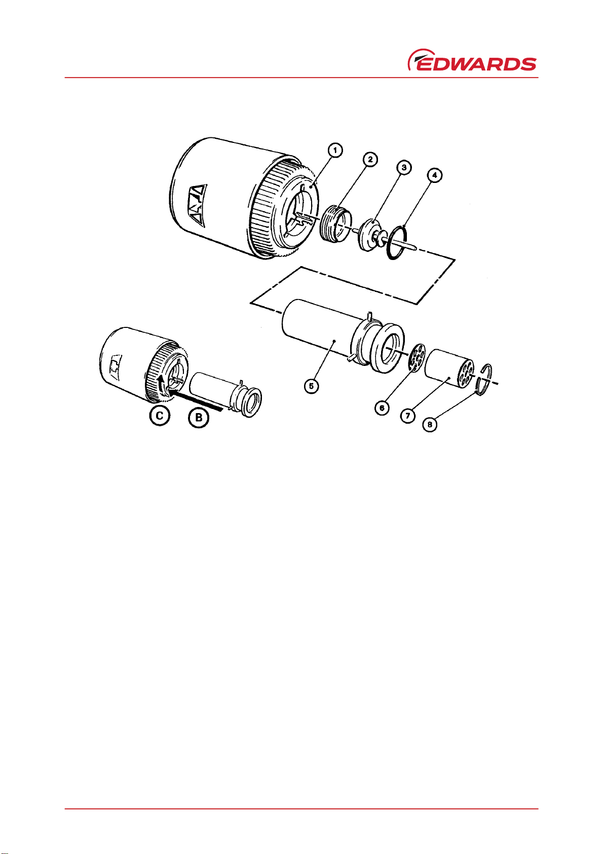
The internal components of the AIM Gauge are shown in Figure 4. The AIM Gauge is designed so that you can easily
clean these components, or use the spares listed in Section 7 to replace these components. Refer to the following
sections for details of the maintenance procedures, which you should do when necessary.
5.2 Replace the Body Tube
Refer to Figure 4 and use the following procedures to replace the body tube:
5.2.1 Remove the AIM Gauge from the Vacuum System
1. Switch off the AIM Gauge electrical supply and ensure that vacuum system is at atmospheric pressure.
2. Disconnect the cable connector plug (Figure 1, item 5) from the AIM Gauge and remove the AIM Gauge from the
vacuum system.
5.2.2 Fit the New Body Tube
1. Hold the magnet housing (1) and turn the body tube (5) anticlockwise (when viewed from the vacuum flange) to
unlock the bayonet fitting. Remove the body tube from the magnet housing.
2. Slide the new body tube into the magnet housing (1) (as shown by arrow B).
3. Hold the magnet housing (1) and turn the body tube (5) clockwise (when viewed from the vacuum flange) to lock
the bayonet fitting (as shown by arrow C).
5.2.3 Refit the AIM Gauge To the Vacuum System
Refit the AIM Gauge to the vacuum system as described in Section 3.2 and refit the cable connector plug to the socket
on the AIM Gauge (Figure 1, item 6).
5.3 Replace the Electrode Assembly
Refer to Figure 4 in the following procedure.
1. Remove the AIM Gauge from the vacuum system as described in Section 5.2.1.
2. Remove the body tube from the AIM Gauge as described in Step 1 of Section 5.2.2.
WARNING
Do not disconnect the electronics and magnet housing from the body tube when the body tube is
connected to the vacuum system. If there is a plasma discharge in the vacuum system near the
body tube, the body tube can become electrically charged.
WARNING
Disconnect the cable from the AIM Gauge before you remove the AIM Gauge from the vacuum
system. High voltages are generated inside the AIM Gauge.
D14558880 Issue H
Page 12 © Edwards Limited 2020. All rights reserved.
Edwards and the Edwards logo are trademarks of Edwards Limited.
This page has been intentionally left blank.
3. Fit the flat spanner supplied in the electrode assembly kit (refer to Section 7) to the two lugs in the end of the
collar (2), then turn the collar anticlockwise to unscrew the collar from the body tube (5) and remove the anode
assembly (3) and the ‘O’ ring (4).
4. Use circlip pliers to remove the circlip (8) from the vacuum flange end of the body tube (5), then remove the
cathode tube (7) and the cathode plate (6).
5. Fit the new cathode plate (6) and cathode tube (7) into the body tube and secure with the circlip (8).
6. Fit the new ‘O’ ring (4) and anode assembly (3) into the body tube (5); ensure that the orientation of the anode
assembly is correct.
7. Refit the collar (2) to the body tube. Locate the flat spanner on the two lugs on the collar and turn the collar
clockwise until it is fully secured in the body tube.
8. Refit the body tube (5) to the magnet housing (1) as described in Steps 2 and 3 of Section 5.2.2. Refit the AIM
Gauge to the vacuum system as described in Section 5.2.3.
Figure 4 - Exploded View of the AIM Gauge
KEY
1 Magnet housing 2 Collar
3 Anode assembly 4 “O” ring
5 Body tube 6 Cathode plate
7 Cathode tube 8 Circlip

© Edwards Limited 2020. All rights reserved. Page 13
Edwards and the Edwards logo are trademarks of Edwards Limited.
MAINTENANCE
D14558880 Issue H
5.4 Replacing the Electronics and Magnet Housing
The magnet housing and end-cap contain the AIM Gauge control electronics. Replace the complete unit as described
below.
1. Remove the AIM Gauge from the vacuum system as described in Section 5.2.1.
2. Remove the body tube from the AIM Gauge as described in Step 1 of Section 5.2.2.
3. Dispose of the old magnet housing and end-cap (refer to Section 6).
4. Fit the body tube to the new magnet housing and end-cap as described in Steps 2 and 3 of Section 5.2.2. Refit
the AIM Gauge to the vacuum system as described in Section 5.2.3.
5.5 Clean the internal components
Refer to Figure 4 in the following procedure.
1. Remove the internal components from the magnet housing as described in Steps 1 to 4 of Section 5.3.
2. The anode assembly (3) has two brackets mounted close to the disk on the anode. Use a strip of fine emery
paper to clean the gap between the disk and the brackets.
3. Use a fine screwdriver or feeler gauge and ensure that the gaps are a minimum of 0.25 mm.
4. Degrease the cathode plate (6), cathode tube (7), body tube (5) and anode assembly (3) in a suitable degreasing
agent.
5. Thoroughly soak the components in a suitable laboratory detergent.
6. Rinse the components in clean water to remove the detergent.
7. Rinse the components in methanol to remove all of the water, then thoroughly dry the components.
8. Refit the components in the magnet housing as described in Steps 5 to 8 of Section 5.3.
5.6 Fault Finding
The AIM Gauge has self-monitoring fault detection circuits which close an error output signal when the gauge is not
operating correctly. You can use the error signal output to determine if a fault has been detected, as described in
Section 4.4.
If the AIM Gauge does not operate correctly, ensure that the electrical connections are correct (refer to Section 3)
and ensure that your electrical supply is suitable for the AIM Gauge (refer to Section 2).

D14558880 Issue H
Page 14 © Edwards Limited 2020. All rights reserved.
Edwards and the Edwards logo are trademarks of Edwards Limited.
This page has been intentionally left blank.
This manual suits for next models
1
Table of contents
Other Edwards Industrial Equipment manuals

Edwards
Edwards CDP User manual

Edwards
Edwards APG-M-NW16 AL User manual

Edwards
Edwards Iron Worker User manual

Edwards
Edwards AIM-P-NW25 User manual

Edwards
Edwards FL20K User manual

Edwards
Edwards GV250 User manual

Edwards
Edwards Drystar GV80-EH250 User manual
Edwards
Edwards AdaptaBeacon 96DV2-N5 Series User manual

Edwards
Edwards FL20K User manual

Edwards
Edwards E1M40/80 Installation instructions


