EG&G ORTEC 118A User manual
100
MIDLAND
ROAD.
OAK
RIDGE,
TENNESSEE,
37830
AREA
CODE
(615)
483-8451
TWX
810-572-1078
INSTRUCTION
MANUAL
118A
PREAMPLIFIER
•
I
ii
^
^
Li"k
is
^
i
y
il
tL'
is
^
QUEEN'S
UNIVERSITY
EBsCS
COMPANY

®
INSTRUCTION
MANUAL
118A
PREAMPLIFIER
Serial
No.
Purchaser
Date
Issued
r
;
INCORPORATED
P.
0.
BOX
C
OAK
RIDGE,
TENNESSEE
37830
Telephone
(615)
483-8451
TWX
810-572-1078
ORTEC
IncorporatecJ
1966
Printed
In
UaS«A«
TABLE
OF
CONTENTS
Page
WARRANTY
PHOTOGRAPH
1.
DESCRIPTION
1-1
2.
SPECIFICATIONS
2-1
3.
INSTALLATION
INSTRUCTIONS
3-1
3.1
Connection
to
Detector
3-1
3.2
Operation
Above
lOOOV
Detector
Bias
3-1
3.3
Connection
to
a
Shaping
Main
Amplifier
3-1
3.4
Input
Power
3-2
3.5
Test
Pulse
3-2
4.
OPERATING
INSTRUCTIONS
4-1
4.1
Detector
Bias
4-1
4.2
Linear
Output
4-1
5.
CIRCUIT
DESCRIPTION
5-1
5.1
Charge-Sensitive
Loop
5-1
5.2
Voltage
Amplifier
5-1
5.3
Cable
Driver
5-1
5.4
Performance
Data
5-1
6.
MAINTENANCE
INSTRUCTIONS
6-1
6.1
Testing
Performance
6-1
6.2
Suggestions
for
Troubleshooting
6-3
BLOCK
DIAGRAM
and
SCHEMATIC
118A-0400-B1 118A-0000-S1
STANDARD
WARRANTY
FOR
ORTEC
ELECTRONIC
INSTRUMENTS
DAMAGE
IN
TRANSIT
Shipments
should
be
examined
immediately
upon
receipt
for
evidence
of
external
or
con
cealed
damage.
The
carrier
making
delivery
should
be
notified
immediately
of
any
such
damage,
since
the
carrier
is
normally
liable
for
damage
in
shipment.
Packing
materials,
v^aybills,
and
other
such
documentation
should
be
preserved
in
order
to
establish
claims.
After
such
notification
to
the
carrier,
notify
ORTEC
of
the
circumstances
so
that
we
may
assist
in
damage
claims
and
in
providing
replacement
equipment
when
necessary.
WARRANTY
ORTEC
warrants
its
electronic
products
to
be
free
from
defects
in
workmanship
and
materials,
other
than
vacuum
tubes
and
semiconductors,
for
a
period
of
twelve
months
from
date
of
ship
ment,
provided
that
the
equipment
has
been
used
in
a
proper
manner
and
not
subjected
to
abuse.
Repairs
or
replacement,
at
ORTEC
option,
will
be
made
without
charge
at
the
ORTEC
factory.
Shipping
expense
will
be
to
the
account
of
the
customer
except
in
cases
of
defects
discovered
upon
initial
operation.
Warranties
of
vacuum
tubes
and
semiconductors,
as
made
by
their
manufacturers,
will
be
extended
to
our
customers
only
to
the
extent
of
the
manufacturers'
liability
to
ORTEC.
Specially
selected
vacuum
tubes
or
semiconductors
cannot
be
warranted.
ORTEC
reserves
the
right
to
modify
the
design
of
its
products
without
incurring
responsibility
for
modification
of
previously
manufactured
units.
Since
installation
conditions
are
beyond
our
control,
ORTEC
does
not
assume
an^
risks
or
liabilities
associated
with
the
methods
of
installation,
or
installation
results.
QUALITY
CONTROL
Before
being
approved
for
shipment,
each
ORTEC
instrument
must
pass
a
stringent
set
of
quality
control
tests
designed
to
expose
any
flaws
in
materials
or
workmanship.
Permanent
records
of
these
tests
are
maintained
for
use
in
warranty
repair
and
as
a
source
of
statistical
information
for
design
improvements.
REPAIR
SERVICE
ORTEC
instruments
not
in
warranty
may
be
returned
to
the
factory
for
repairs
or
checkout
at
modest
expense
to
the
customer.
Standard
procedure
requires
that
returned
instruments
pass
the
same
quality
control
tests
as
those
used
for
new
production
instruments.
Please
contact
the
factory
for
instructions
before
shipping
equipment.

■■y^L
"■
DET.
INPUT
mM.
m
PULSE
POWER
WARRANTY
VOID
The
warranty
is
voided
unless
the
following
precautions
are
taken:
DO
NOT
connect
a
detector,
coble,
capacitor,
or
other
copocitive
device
or
low
impedance
to
the
DET.
INPUT
connector,
shown
in
the
Front
View
on
page
ii
of
this
manual,
unless
the
detector
bias
circuitry
is
COMPLETELY
DISCHARGED.
(Refer
to
explanation
below.)
The
input
transistor
wil
I
be
destroyed
if
the
DET.
INPUT
connector
is
shorted,
i.e.,
by
connecting
a
detector,
cable,
capacitor,
or
other
capacitive
device
such
as
a
voltmeter
probe,
etc.,
while
the
detector
bios
components
are
charged.
A
short
circuit,
short-term
or
continuous,
will
cause
the
applied
bias
voltage
(stored
on
C3)
to
be
coupled
via
C3
directly
to
the
input
transistor,
causing
catastrophic
breakdown.
If
this
happens,
the
only
recourse
is
to
replace
Q1
and
perhaps
Q2
also,
depending
on
the
failure
mode
of
Q1
.
To
discharge
the
detector
bias
circuitry
requires
that
either
a
low
impedance
(short
cir
cuit
preferable)
be
connected
across
the
DET.
BIAS
connector,
shown
in
the
Rear
View
on
page
ii,
for
at
least
one
minute,
or
the
bias
supply
voltage
be
reduced
to
zero
for
a
time
adequate
to
discharge
the
input
coupling
capacitor.
A
shorting
cap
is
provided
at
the
DET.
BIAS
connector
for
the
purpose
of
discharging
the
bias
circuitry
and
keeping
it
discharged
when
preamp
is
not
in
use.
If
a
variable
bias
supply
is
used,
merely
turning
down
the
voltage
control
to
zero
and
leaving
it
for
at
least
one
minute
will
suffice,
since
the
bias
circuitry
can
discharge
itself
through
the
output
impedance
of
the
bios
supply.
Sometimes
it
is
necessary
to
simply
disconnect
the
bias
supply,
such
as
when
using
batteries
for
bios.
This
situation
leaves
no
discharge
path,
so
a
path
must
be
provided
by
placing
a
short
circuit
or
low
impedance
across
the
DET.
BIAS
connector
on
the
rear
panel
of
the
unit.
(Use
shorting
cop
provided.)
DO
NOT
SHORT
the
DET.
INPUT
connector
on
the
front
panel.
This
problem
has
been
studied
extensively,
and
any
attempt
to
protect
the
input
tran
sistor
by
limiting
the
voltage
swing
by
the
use
of
diodes,
zeners,
etc.,
degrades
the
resolution
to
approximately
5.5
keV
(Si)
and
degrades
the
slope
to
approximately
0.15
keV/pF.

1-1
ORTEC
118A
PREAMPLIFIER
1.
DESCRIPTION
(See
Block
Diagram,
118-0400-B)
The
ORTEC
118A
Preamplifier
is
intended
for
use
with
cooled,
low-leakage
semi
conductor
detectors
having
relatively
low
(0
to
100
pF)
capacity.
In
order
to
achieve
the
high
performance
specified,
the
detector
bios
resistor
is
necessarily
large
(2000
megohms),
and
therefore
the
voltage
drop
across
this
resistor
can
be
significant
with
detectors
having
high
leakage.
The
118A
is
an
all-transistor
preamplifier
using
a
field-effect
transistor
in
the
input
stage.
The
preamplifier
contains
a
charge-sensitive
stage
having
an
open
loop
gain
greater
than
20,000
followed
by
a
voltage
amplifier
with
switch-selectable
gains
of
0.5
and
5.
The
voltage
amplifier
is
followed
by
a
cable
driver
capable
of
driving
a
93-ohm
cable
(series
terminated
at
the
preamplifier
end)
to
±7V.
When
the
preamp
is
operated
at
high
counting
rotes,
there
is
a
possibility
that
the
input
pulses
will
pile
up
and
cause
the
preamplifier
to
saturate.
In
order
to
opti
mize
the
preamplifier
counting
rote
capabilities,
a
SO-psec
clip
(RC
differentiation)
has
been
inserted
between
the
charge-sensitive
stage
and
the
voltage
amplifier.
With
the
addition
of
this
clip,
both
the
charge-sensitive
stage
and
the
voltage
ampli
fier
saturate
at approximately
the
same
level.
The
counting
rate
capabilities
of
the
118A
for
various
energies
are
shown
in
the
following
table:
Input
Energy
Count
Rate
With
«1%
(silicon
equivalent)
counting
losses
(cts/sec)
100
KeV
«2
X
10^
1
MeV
«2
X
10^
10
MeV
ft
.2
X
104

2-1
2.
SPECIFICATIONS
Basis
of
Warranty:
<.03
keV/pF
fwhm
Ge
slope,
si
.5
keV
fwhm
Ge
at
0
pF
input
capacity.
Typical
performance
is
shown
below:
TYPICAL
PERFORMANCE
Noise
with
2p
sec
RC
Main
Amp
Ext
Cap.
(pF)
Resolution
keV
(Ge)
Resolution
keV
(Si)
Eq.
Noise
Chg.
rms
electrons
Relative
Amplitude
Rise
Time
(nsec)
0
1.19
1.48
175
1.00
48
5
1.26
1.57
185
1.00
52
10
1.40
1.74
205
1.00
56
15
1.53
1.90
224
1.00
65
25
1.80
2.24
264
1.00
72
50
2.50
3.11
367
1.00
103
100
4.0
4.98
587
.995
168
200
6.9
8.6
1015
.985
280
500
15.0
18.6
2200
.950
580
1000
27.5
34.2
4040
.900
1000
Output
pulse
shape
Rise
time
as
in
table
above;
exponential
fal
l
with
50-psec
time
constant
Integral
nonlinearity
sO.1%
for
0-5V
with
internal
series
termination
Temperature
coefficient
±0.01%
per
°C
Detector
bias
isolation
1000V
dc
with
Microdot
connector
in
place;
2000V
dc
without
Microdot
connector
1
I

2-2
I
Input
open
loop
gain
>20,000
Power
required
+24V
dc
at
18
mA,
-24V
dc
at
18
mA;
supplied
from
ORTEC
main
amplifier
or
from
on
ORTEC
115
Preamplifier
Power
Supply
Cable
required
10-foot
compatible
cable
supplied
with
preamplifier,
type
108-C2
Power
connector
Ampheno!
17-20090
Saturated
output
amplitude
7V
at
end
of
several
hundred
feet
of
unterminated
93-ohm
cable
Output
source
impedance
Adjustable
from
50
to
150
ohms
Charge
gain
300
mV/MeV
in
XI0
gain
position
(silicon),
365
mV/MeV
(germanium);
30
mV/MeV
in
XI
gain
position
(silicon),
36.5
mV/MeV
(germanium)
Detector,
output,
and
test
pulse
connectors
BNC
Detector
bias
connector
MHV,
Gremar
6317
Size
1.8
X
4
X
6
inches
(4.5
x
10.2
x
15.3
cm)
Weight
Net,
1.5
pounds
(0.7
kg);
gross,4.0
pounds
(1.8
kg)
S
3.
AI
V
CM-C
r
0-
O
kf
C
V«
,
•1/
c
A
^7
,
%
^
.0

3-1
3.
INSTALLATION
INSTRUCTIONS
3.1
Connection
to
Detector
A
direct
connection
with
shielded
coaxial
cable
should
be
made
between
the
detector
and
the
Microdot
connector
labeled
DET.
INPUT
on
the
front
panel.
DO
NOT
CONNECT
THE
DETECTOR
TO
THE
INPUT
CONNECTOR
UNTIL
THE
DETECTOR
BIAS
VOLTAGE
HAS
BEEN
REDUCED
TO
ZERO.
FAILURE
TO
DO
THIS
WILL
CAUSE
CATASTROPHIC
DAMAGE
TO
THE
INPUT
FIELD
EFFECT
TRANSISTOR.
The
performance
of
the
118A
Preamplifier,
like
that
of
all
other
such
low-
noise
nuclear
amplifiers,
is
degraded
as
the
capacity
at
the
input
of
the
amplifier
increases;
for
this
reason,
it
is
important
that
the
length
of
coaxial
cable
used
between
the
amplifier
and
the
detector
be
kept
at
the
minimum
necessary.
Also,
it
is
preferable
to
use
93-
or
100-ohm
impedance
cable
rather
than
75-
or
50-ohm
cable,
since
the
capacity
per
foot
is
less
for
the
higher-
impedance
cable,
Microdot
cables
and
fittings
of
the
series
stocked
and
supplied
by
ORTEC
are
suitable.
The
cable
is
100-ohm
impedance,
13
pF
per
foot.
An
adapter,
ORTEC
No,
C-16,
may
be
used
on
the
input
Microdot
connector
to
permit
use
of
the
BNC
cables,
(See
pages
6-6
and
6-7,)
Once
the
input
cable
installation
has
been
made,
the
electronic
noise
perform
ance
of
the
preamp
can
be
predicted
by
calculating
the
cable
capacity
from
the
above
information,
adding
the
capacity
expected
from
the
detector,
and
referring
to
the
table
of
typical
performance
versus
input
capacity
(Section
2).
3.2
Operating
Above
1000V
Detector
Bias
If
it
is
desired
to
operate
the
detector
at
more
than
1000
volts,
the
Microdot
detector
input
connector
must
be
removed,
since
it
wil
l
not
take
more
than
1000
volts.
The
components
in
the
bias
circuitry
are
rated
for
up
to
2000
volts,
and
the
unit
may
be
operated
at
up
to
2000
volts
if
some
arrangement
is
made
to
get
the
detector
connection
inside
the
preamp
with
good
shielding.
This
is
some
times
done
by
removing
the
input
connector,
mounting
the
preamp
rigidly
against
the
outside
of
the
vacuum
wall,
and
letting
the
vacuum
feedthrough
protrude
directly
into
the
inside
of
the
preamp,
where
connection
is
made
with
the
wire
that
was
connected
to
the
input
connector.
3.3
Connection
to
a
Shaping
Main
Amplifier
The
preamp
can
be
used
to
drive
long
93-ohm
line
to
a
shaping
main
amplifier,
and
is
designed
to
be
directly
compatible
with
the
ORTEC
transistor
main
ampli
fiers.
It
can
be
used
with
any
shaping
main
amplifier
if
a
power
supply
is
used
to
power
the
preamp
,
3-2
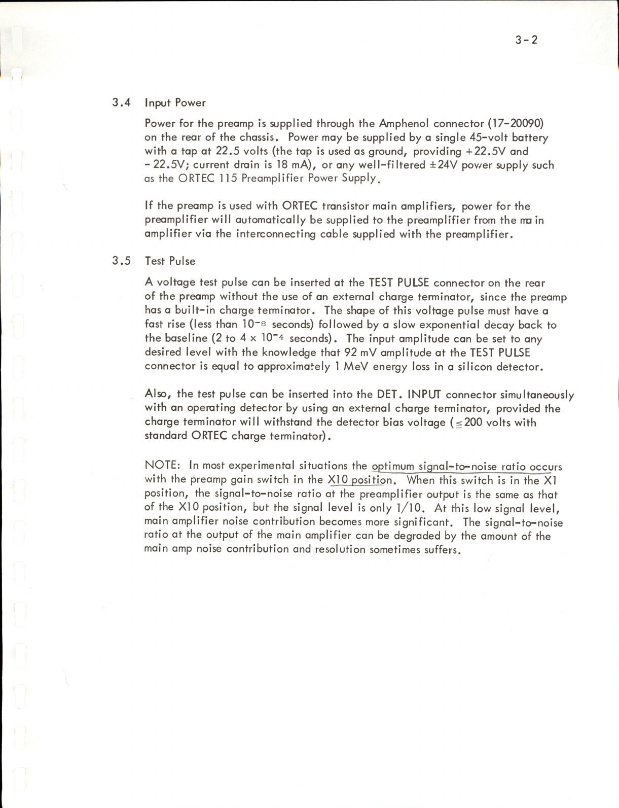
3.4
Input
Power
Power
for
the
preamp
is
supplied
through
the
Amphenol
connector
(17-20090)
on
the
rear
of
the
chassis.
Power
may
be
supplied
by
a
single
45-volt
battery
with
a
tap
at
22.5
volts
(the
tap
is
used
as
ground,
providing
+22.5V
and
-
22.5V;
current
drain
is
18
mA),
or
any
well-filtered
±24V
pov/er
supply
such
as
the
ORTEC
115
Preamplifier
Power
Supply.
If
the
preamp
is
used
with
ORTEC
transistor
main
amplifiers,
power
for
the
preamplifier
will
automatically
be
supplied
to
the
preamplifier
from
the
tru
in
amplifier
via
the
interconnecting
cable
supplied
with
the
preamplifier.
3.5
Test
Pulse
A
voltage
test
pulse
can
be
inserted
at
the
TEST
PULSE
connector
on
the
rear
of
the
preamp
without
the
use
of
an
external
charge
terminator,
since
the
preamp
has
a
built-in
charge
terminator.
The
shape
of
this
voltage
pulse
must
have
a
fast
rise
(less
than
10~8
seconds)
followed
by
a
slow
exponential
decay
back
to
the
baseline
(2
to
4
x
10"4
seconds).
The
input
amplitude
can
be
set
to
any
desired
level
with
the
knowledge
that
92
mV
amplitude
at
the
TEST
PULSE
connector
is
equal
to
approximately
1
MeV
energy
loss
in
a
silicon
detector.
Also,
the
test
pulse
can
be
inserted
into
the
DET.
INPUT
connector
simultaneously
with
an
operating
detector
by
using
an
external
charge
terminator,
provided
the
charge
terminator
will
withstand
the
detector
bias
voltage
(s200
volts
with
standard
ORTEC
charge
terminator).
NOTE:
In
most
experimental
situations
the
optimum
signal-to-noise
ratio
occurs
with
the
preamp
gain
switch
in
the
XI0
position.
When
this
switch
is
in
the
XI
position,
the
signal-to-noise
ratio
at
the
preamplifier
output
is
the
same
as
that
of
the
XI0
position,
but
the
signal
level
is
only
l/lO.
At
this
low
signal
level,
main
amplifier
noise
contribution
becomes
more
significant.
The
signal-to-noise
ratio
at
the
output
of
the
main
amplifier
can
be
degraded
by
the
amount
of
the
main
amp
noise
contribution
and
resolution
sometimes
suffers.

4-1
OPERATING
INSTRUCTIONS
4.1
Detector
Bias
Detector
bias
is
applied
to
the
preamplifier
through
the
high-voltage
MHV
connector
(UG-931/U).
The
detector
bios
components
are
rated
at
2000V
and
connectors
are
rated
at
1000
volts.
Inside
the
preomp,
the
detector
bias
is
applied
to
the
DET.
INPUT
connector
through
a
decoupling
network
con
sisting
of
R1
(10-megohm),
R2
(2000-megohm),
and
C1
(0.0022pF)
so that
the
total
resistance
in
series
with
the
detector
bias
is
2010
megohms.
This
resistance
must
be
taken
into
account
when
considering
the
bias
voltage
actu
ally
applied
to
a
leaky
detector.
The
voltage
dropped
in
this
network
will
be
2010
volts
for
each
microampere
of
detector
leakage
current.
It
will
be
necessary
to
increase
the
bias
supply
output
voltage
to
compensate
for
this
drop.
EXAMPLE:
It
is
desired
to
operate
a
detector
at
100
volts
bias.
Detector
leakage
at
100
volts
=
0.05
microampere.
The
drop
in
the
bias
network
=(0.05
x
10"®)=
(2000
x
10®)
=
100.5
volts
Voltage
required
at
bias
supply
=
100
+
100.5
=
200.5
volts.
4.2
Linear
Output
The
output
of
the
preomp
is
a
"step"
of
voltage
of
300
mV/MeV
with
the
gain
switch
in
the
X10
position,
or
30
mV/MeV
in
the
XI
position
(silicon
detector
equivalents).
The
dynamic
range
of
the
output
is
7
volts,
either
polarity,
when
the
output
is
"sending-end"
terminated.
"Receiving-end"
termination
will
result
in
a
3.5-volt
dynamic
range,
but
this
may
be
preferable
to
sending-end
termination.
The
integral
nonlinearity
in
the
preomp
is
specified
at
not
greater
than
0.1%
over
the
0
to
10
MeV
range.

5-
1
5.
CIRCUIT
DESCRIPTION
(See
Schematic
Diagram
118-0000-A-S)
5.1
Charge-Sensitive
Loop
The
charge-sensitive
loop
consists
of
five
transistors
acting
as
an
operatiorKil
amplifier
with
capacitive
feedback.
Transistors
Q1
and
Q2
operate
in
cascode
and
drive
Q3,
Q4,
and
Q5
in
a
low
impedance
driver
configuration
for
low
output
impedance
and
fast
rise
time.
The
rise
time
of
the
charge-sensitive
loop
output
increases
as
the
external
input
(detector)
capacitance
is
increased.
5.2
Voltage
Amplifier
The
voltage
amplifier
is
designed
for
fast
rise
time
(20
nanoseconds
in
the
XI
gain
position)
so
as
to
faithfully
reproduce
the
pulse
from
the
charge-sensitive
loop.
In
the
XIO
gain
position
the
voltage
amplifier
has
a
rise
time
of
approx
imately
40
nanoseconds
even
at
low
capacitance
values.
In
the
XIO
gain
position
the
preamplifier
overall
rise
time
does
not
change
until
the
charge-
sensitive
loop
rise
time
approaches
40
nanoseconds,
as
external
capacitance
is
increased.
5.2.1
Pole-Zero
Cancellation
Network
The
decay
time
constant
of
the
output
signal
from
the
preamplifier
is
deteimined
by
C12
and
the
parallel
combination
of
R17, R18,
and
R36.
It
is
accurately
set
at
50
microseconds.
R36
C12
is
a
1
millisecond
time
constant
in
the
proper
configuration
to
provide
a
"zero"
type
frequency
response
which
cancels
out
the
1
mil
lisecond
"pole"
generated
by
the
charge
sensitive
loop
feedback
time
constant.
The
purpose
of
this
"Pole-
Zero
Cancellation"
is
to
obtain
a
pulse
response
which
has
a
step
rise
with
a
single
50
microsecond
decay
time
constant
back
to
the
baseline
without
appreciable
undershoot.
This
will
allow
accurate
pole-zero
cancel
lation
in
the
shaping
amplifier.
5.3
Cable
Driver
The
cable
driver
consists
of
Q8,
Q9,
QIO,
and
Q11
operating
in
a
complementary
Darlington
connection.
This
circuit
gives
extremely
good
linearity
and
an
output
impedance
of
a
few
ohms.
However,
51
ohms
is
inserted
in
series
with
each
cir
cuit,
so
that
the
minimum
output
impedance
(R35
at
0
ohms)
is
51
ohms.
The
maximum
output
impedance
is
150
ohms
(R31
at
ICQ
ohms),
so
that
cables
in
the
ra
nge
of
50
to
150
ohms
can
be
series
(sending-end)
terminated.
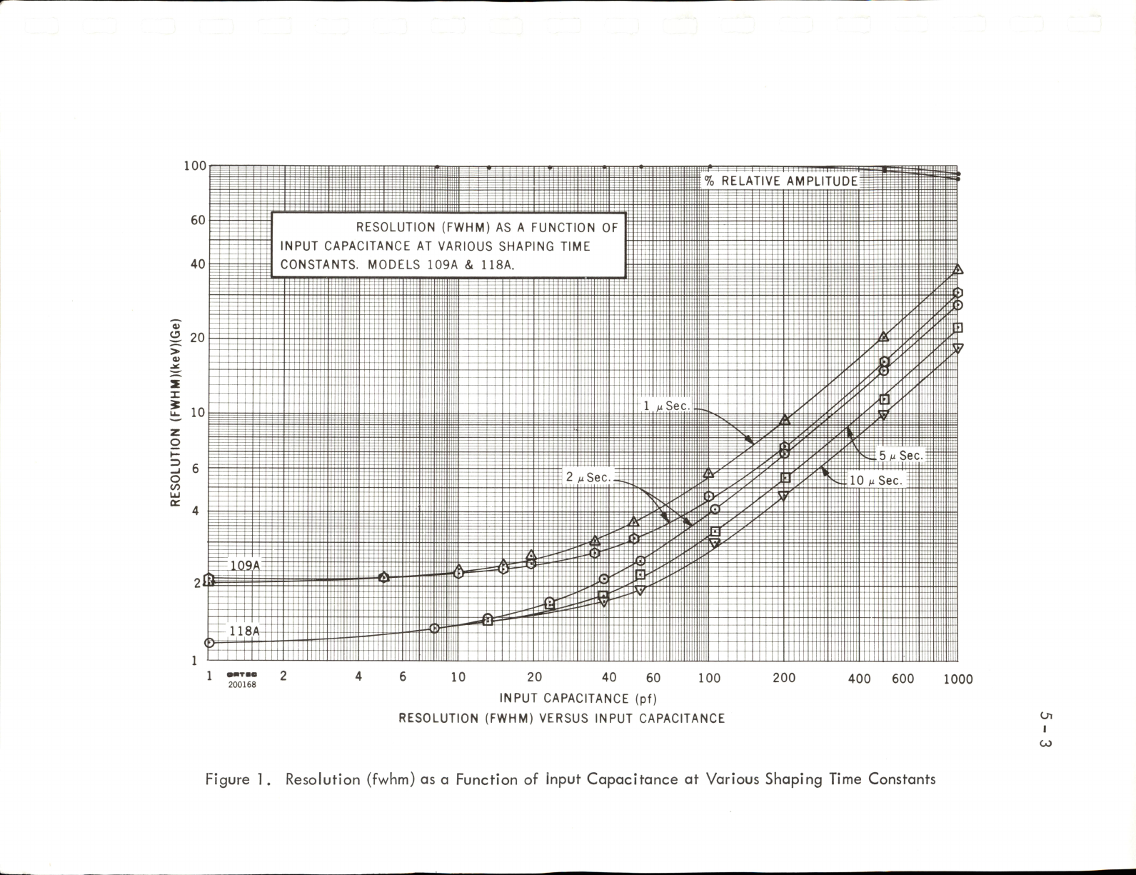
5.4
Performance
Data
Figure
1
shows
typical
performance
characteristics
of
the
preamp
on
relative
amplitude
and
resolution
(fwhm)
as
a
function
of
external
capacitance
on
the
input
of
the
preamp
for
1
psec,
2psec,
5Hsec,
and
lOpsec
single
RC
integration
and
differentiation
time
constants.
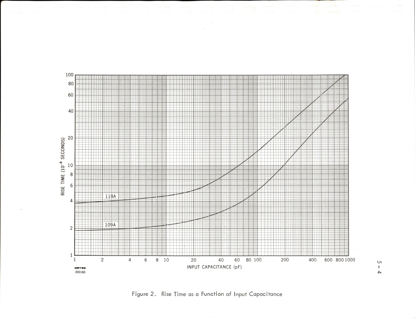
Figure
2
shows
rise
time
as
a
function
of
in-
5-2
put
capacitance.
All
data
were
taken
with
an
ORTEC
410
Linear
Amplifier.
Figure
3
shows
the
detrimental
effect
of
decreasing
the
bias
resistor,
R3,
to
values
less
than
2000
megohms.
It
is
conceivable
that
it
may
be
desired
to
de
crease
the
value
of
R3,
e.g.,
when
using
the
preamp
with
room
temperature
detectors
which
may
have
appreciable
leakage
current.
The
effect
of
decreasing
R3
is
shown
at
both
zero
external
capacitance
and
55
pF
external
capacitance.
The
detrimental
effect
of
decreasing
R3
is
less
when
the
external
(detector)
capaci
tance
is
appreciable.
100
i±H44=t
RELATIVE
AMPLITUDE
RESOLUTION
(FWHM)
AS
A
FUNCTION
OF
INPUT
CAPACITANCE
AT
VARIOUS
SHAPING
TIME
CONSTANTS.
MODELS
109A
&
118A.
H
10
5
M
Sec
2
uSec
10
m
Sec.
118A
•■m
2
200168
20 40
60
100
INPUT
CAPACITANCE
(pf)
RESOLUTION
(FWHM)
VERSUS
INPUT
CAPACITANCE
200
400
600
1000
Oi
I
CO
Figure
1.
Resolution
(fwhm)
as
a
Function
of
Input
Capacitance
at
Various
Shaping
Time
Constants
8
10
Qtirn
200160
20
40
60
80
100
200
INPUT
CAPACITANCE
(pF)
400
600
800
1000
Oi
Figure
2.
Rise
Time
as
a
Function
of
Input
Capacitance

700
<
s
ce
ui
(S
>
«
o
I/)
Ui
fl
C
600„
400
O
200200
50
100
200
500
1000
2000
BIAS
RESISTOR
VALUE
(MEGOHMS)
5000
Oi
Figure
3.
Resolution
(fwhm)
os
a
Function
of
Bias
Resistor

6-
1
6.
MAINTENANCE
INSTRUCTIONS
6.1
Testing
Performance
As
ordinarily
used
in
a
counting
or
spectroscopy
system,
the
preamp
is
one
part
of
a
series
system
involving
the
source
of
particles
to
be
analyzed,
the
detector,
the
preamp,
the
main
amplifier,
and
the
pulse
height
analyzer.
In
situations
where
proper
results
are
not
being
obtained
and
tests
for
proper
performance
of
the
preamp
and
the
other
components
are
indicated,
it
is
important
to
realize
that
rapid
and
logical
testing
is
possible
only
when
the
individual
components
are
separated
from
the
series
system.
In
proving
the
performance
of
the
preamp,
this
consists
of
removing
it
from
the
system
and
dealing
with
it
alone,
by
providing
a
known
electrical
input
signal
and
testing
for
proper
output
signal
with
an
oscilloscope.
6.1.1
Use
a
voltage
pulse
in
the
TEST
PULSE
jack,
as
outlined
in
Section
3.5,
or
use
a
pulser
with
a
charge
terminator
at
the
DET.
INPUT
jack.
The
polarity
of
the
test
pulse
signal
should
be
in
agreement
with
the
expected
signal
input
polarity
from
a
detector.
6.1.2
If
a
suitable
input
signal
has
been
obtained
for
the
preamp
as
outlined
in
the
preceding
section,
the
performance
of
the
instrument
may
be
checked
by
observing
the
pulse
waveform
at
the
OUTPUT
jack.
If
an
input
signal
of
920
mV,
corresponding
to
about
10
MeV,
has
been
obtained
as
described
above,
one
can
expect
an
output
pulse
amplitude
of
about
3.0
volts
with
the
gain
switch
in
the
XIO
position,
and
0.3
volt
with
the
gain
switch
in
the
XI
position.
6.1.3
The
noise
contribution
of
the
preamplifier
may
be
verified
by
two
basic
methods.
In
either
case,
the
normal
capacity
of
the
detector
and
associated
cables
should
be
replaced
by
a
capacitor
of
equal
value
connected
to
the
DET.
INPUT
jack.
This
is
necessary
because
the
noise
contribution
of
the
preamplifier
is
dependent
upon
input
capacity,
as
can
be
seen
from
the
noise
specifications
given
in
Section
2.
The
only
meaningful
statement
of
the
noise
level
of
the
preamplifier
is
one
that
relates
to
the
spread
caused
by
the
noise
in
actual
spectra.
This
can
be
measured
and
expressed
in
terms
of
the
ful
l
width
at
half
maxi
mum
of
a
monoenergetic
signal
after
passing
through
the
preamplifier
and
main
amplifier
system.
The
noise
performance
referenced
in
Section
2
is
stated
in
these
terms,
and
verification
methods
wil
l
be
described.
If
desired,
the
preamplifier
can
be
tested
with
no
external
capacity
on
the
DET.
INPUT
jack,
inwhich
case
the
noise
width
should
be
approxi
mately
that
shown
for
zero
external
capacity.
In
any
case,
the
input
jack
and
capacitors,
when
used,
should
be
completely
shielded
electri
cal
ly.
A
wrapping
of
aluminum
foil
around
the
input
jack
will
suffice
for
testing
at
zero
capacity,
taking
care
not
to
short
the
center
conductor
to
ground.

6-2
The
preamplifier
must
be
tested
in
conjunction
with
an
associated
main
amplifier
that
provides
the
required
pulse
shaping.
The
typical
noise
per
formance
given
in
Section
2
is
based
on
main
amplifier
pulse
shaping
consisting
of
equal
RC
differentiation
and
integration
of
2-microsecond
time
constant.
For
comparison
to
these
tabulated
values,
it
is
preferable
to
test
the
preamplifier
under
identical
pulse
shaping
conditions.
It
is
also
important
to
ensure
that
the
noise
level
of
the
input
stage
of
the
associated
main
amplifier
does
not
contribute
materially
to
the
total
noise.
This
is
usually
no
problem
provided
input
attenuators,
if
any,
on
the
main
amplifier
are
set
for
minimum
attenuation.
If
a
multichannel
pulse
height
analyzer
is
used
following
the
main
ampli
fier,
testing
of
the
noise
performance
can
be
accomplished
merely
by
using
a
calibrated
test
pulse
generator
with
charge
terminator,
as
outlined
in
Section
6.1.1
.
With
only
the
charge
terminator
connected
to
the
DET.
INPUT
jack,
the
spread
of
the
pulser
peak
thus
analyzed
will
be
due
only
to
the
electronic
noise
contribution
of
the
preamplifier
and
main
amplifier.
The
analyzer
can
be
calibrated
in
terms
of
keV
per
channel
by
observing
two
different
pulser
peaks
of
known
energy,
and
the
fwhm
of
a
peak
can
be
taken
directly
from
the
analyzer
readout.
It
is
also
possible
to
determine
the
noise
performance
of
the
preamplifier
by
the
use
of
a
wide-bandwidth
rms
ac
voltmeter
such
as
the
Hewlett-
Packard
400D,
reading
the
main
amplifier
output
noise
level
and
correlating
with
the
expected
pulse
amplitude
per
keV
of
input
signal
under
the
same
conditions.
Again,
a
calibrated
test
pulse
generator
is
required
for
an
accurate
measurement.
In
this
method,
the
preamplifier
and
main
amplifier
are
set
up
as
they
would
be
used
normal
ly,
but
with
a
dummy
capacitor
(or
no
capacity)
on
the
DET.
INPUT
jack,
and
with
the
ac
voltmeter
connected
to
the
amplifier
output.
The
noise
voltage
indicated
by
the
meter,
designated
Erms,
'S
read
and
noted.
Then,
a
test
pulse
of
known
energy,
Ejp
(in
keV),
is
applied
to
the
input
jack,
and
the
amplitude
of
the
resulting
output
pulse,
Eq^j.
is
measured
in
volts
with
an
oscilloscope.
The
noise
spread
can
then
be
calculated
from
the
formula
fwhm
(keV,
Si
det.)
=
2.66
(Epms)
(Ein)
^out
where
Epms
's
output
noise
in
volts
on
the
400D
meter,
E|n
is
the
input
signal
in
keV
particle
energy,
Eout
output
signal
in
volts
corresponding
to
the
above
input.
The
factor
2.66
is
the
product
of
two
relations:
correction
from
rms
to
fwhm
(2.35),
and
correction
of
the
4000
meter
from
sine-wave
to
white
noise
(1.13).

6-3
The
noise
performance
of
the
preamplifier,
as
measured
by
the
above
methods,
should
not
differ
significantly
from
that
given
in
the
specifi
cations
in
Section
2.
6.1.4
When
testing
the
preamplifier
and
detector,
if
the
noise
performance
of
the
preamplifier
has
been
verified
as
outlined
in
the
preceding
section,
or
is
otherwise
not
suspect,
a
detector
may
be
tested
to
some
extent
by
duplicating
the
noise
performance
tests
with
the
detector
connected
in
place,
and
with
normal
operating
bias
applied.
The
resulting
combined
noise
measurement,
made
either
with
an
analyzer
or
by
the
voltmeter
method,
indicates
the
sum
in
quadrature
of
the
separate
noise
sources
of
the
amplifier
and
the
detector.
In
other
words,
the
total
noise
is
given
by
(N^ot)^
=
(Njet)^
(Namp)®
•
Each
quantity
is
expressed
in
keV
fwhm.
The
quantity
Njet
'S
known
as
the
"noise
width"
of
the
detector,
and
is
included
as
one
of
the
specified
parameters
of
each
ORTEC
semiconductor
detector.
By
use
of
the
above
equation,
with
a
knowledge
of
the
noise
of
the
preamplifier,
the
noise
width
of
the
detector
can
be
determined.
The
significance
of
this
noise
width
in
evaluating
the
detector
is
subject
to
interpretation,
but
general
ly
the
actual
resolution
of
the
detector
for
protons
or
electrons
will
be
approxi
mately
the
same
as
the
noise
width;
the
resolution
of
the
detector
for
alpha
particles
will
be
poorer
than
the
noise
width.
The
most
useful
application
of
determining
the
noise
width
of
a
detector
is
in
the
occasional
monitoring
of
this
quantity
to
verify
that
the
detector
characteristics
have
not
undergone
any
significant
change
during
use.
6.2
Suggestions
for
Troubleshooting
In
situations
where
the
preamp
is
suspected
of
malfunction,
it
is
important
to
isolate
the
preamp
and
test
it
alone,
not
in
a
system
involving
other
units
such
a
sourceof
particles
to
be
analyzed,
the
detector,
the
preamp,
a
main
amplifier
and
subsequent
sealers
and/or
analyzers.
Such
logical
isolation
and
individual
testing
of
components
will
be
the
most
productive
approach.
6.2.1
Charge-Sensitive
Loop
The
function
of
the
preamp
is
simple
and
lends
itself
to
relatively
easy
scrutiny.
The
charge-sensitive
loop
performs
a
charge-to-voltage
conversion
on
the
input
signal.
It
has
an
output
signal
that
manifests
itself
as
a
fast
rise
(~40
nanoseconds
at
0
pF
external
capacitance)
step
of
voltage
whose
height
is
determined
by
the
input
charge,
followed
by
a
400-microsecond
decay
back
to
the
baseline.
This
signal
can
be
observed
at
the
emitter
of
Q4
while
impressing
a
signal,
as
described
in
Section
3.5.
The
amplitude
of
this
signal
should
be
90
mV
per
MeV
equivalent
input
signal
.
Table of contents
Other EG&G Amplifier manuals

EG&G
EG&G ORTEC 485 User manual

EG&G
EG&G ORTEC 414A Service manual

EG&G
EG&G 113 Service manual

EG&G
EG&G ORTEC 452 User manual

EG&G
EG&G ORTEC 113 Service manual

EG&G
EG&G ORTEC 474 Service manual

EG&G
EG&G ORTEC 444 User manual

EG&G
EG&G ORTEC 427 User manual

EG&G
EG&G ORTEC 575A Service manual

EG&G
EG&G 128A Service manual


