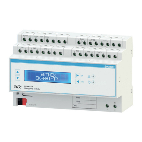
Ekinex EK-HH1-TP Instructions for use

Application Manual
EK-HH1-TP
Mixing group controller

Application Manual
EK-HH1-TP mixing group controller
Release 1.01 - Updating: 12/05/2018 Application Manual
© EKINEX S.p.A. – All rights reserved Pag. 2
Summary
1Scope of the document..................................................................................................................................5
2Product description ........................................................................................................................................6
2.1 General characteristics ..........................................................................................................................6
2.2 Electrical characteristics ........................................................................................................................8
3Switching, display and connection elements.................................................................................................9
4Configuration ............................................................................................................................................... 11
5Programming and commissioning ...............................................................................................................11
6Function description ....................................................................................................................................12
6.1 Switching on.........................................................................................................................................12
6.2 Offline operation...................................................................................................................................12
6.2.1 Operation with bus power only.....................................................................................................12
6.2.2 Operation with load power supply only ........................................................................................12
6.3 Manual operation .................................................................................................................................12
6.3.1 Output status when mode changes .............................................................................................12
6.3.2 Manual mode activation ...............................................................................................................13
6.4 Online operation...................................................................................................................................13
6.4.1 Software working cycle ................................................................................................................13
6.4.2 State variables (communication objects) .....................................................................................13
6.5 Applications..........................................................................................................................................13
6.6 Mixing group management ..................................................................................................................14
6.6.1 Components .................................................................................................................................14
6.6.2 Activation/deactivation sequence.................................................................................................14
6.6.3 Activation......................................................................................................................................14
6.6.4 Heating/cooling changeover.........................................................................................................15
6.6.5 Types of supported servomotors..................................................................................................15
6.6.6 PI (proportional-integral) regulator ...............................................................................................16
6.6.7 Circulator protection function .......................................................................................................16
6.6.8 Anticondensation protection function ...........................................................................................16
6.6.9 Alarms ..........................................................................................................................................17
6.7 Physical inputs .....................................................................................................................................20
6.8 Physical outputs...................................................................................................................................20
6.9 Control modes......................................................................................................................................21
6.9.1 Heating: fixed point ......................................................................................................................21
6.9.2 Heating: climatic compensation ...................................................................................................21
6.9.3 Heating: recalibration based on return temperature ....................................................................22
6.9.4 Heating: recalibration based on internal conditions .....................................................................23
6.9.5 Heating: climatic compensation and recalibration based on internal conditions .........................24
6.9.6 Heating: connecting communication objects of KNX sensors .....................................................25
6.9.7 Cooling: fixed point.......................................................................................................................27
6.9.8 Cooling: climatic compensation....................................................................................................27
6.9.9 Cooling: recalibration based on internal thermohygrometric conditions ......................................28
6.9.10 Cooling: clim. Comp. and recalibration based on internal thermohygrometric conditions ...........28
6.9.11 Cooling: connecting communication objects of KNX sensors......................................................29
7Display .........................................................................................................................................................32
7.1 Navigation buttons ...............................................................................................................................32


Application Manual
EK-HH1-TP mixing group controller
Release 1.01 - Updating: 12/05/2018 Application Manual
© EKINEX S.p.A. – All rights reserved Pag. 3
7.2 Navigation menus ................................................................................................................................32
8Application program for ETS .......................................................................................................................34
8.1 About EK-HH1-TP................................................................................................................................34
8.2 General parameters .............................................................................................................................35
8.3 Inputs ...................................................................................................................................................39
8.4 External sensors from bus ...................................................................................................................43
8.5 Heating.................................................................................................................................................46
8.6 Cooling .................................................................................................................................................50
8.7 Mixing valve output ..............................................................................................................................54
8.8 Logic functions .....................................................................................................................................57
9Appendix......................................................................................................................................................60
9.1 List of KNX communication objects .....................................................................................................60
9.2 Retained communication objects.........................................................................................................64
9.3 Alarms and Error indications................................................................................................................65
9.4 Application examples ...........................................................................................................................67
10 Warnings......................................................................................................................................................72
11 Other information .........................................................................................................................................72

Application Manual
EK-HH1-TP mixing group controller
Release 1.01 - Updating: 12/05/2018 Application Manual
© EKINEX S.p.A. – All rights reserved Pag. 4
Revision
Modifications
Date
1.01
Corrections in section 9.3, concerning Alarms and Error Codes
12/05/2018
1.00
Emission
07/04/2018

Application Manual
EK-HH1-TP mixing group controller
Release 1.01 - Updating: 12/05/2018 Application Manual
© EKINEX S.p.A. – All rights reserved Pag. 5
1 Scope of the document
This application manual describes application details for the A1.0 release of the ekinex®controller EK-HH1-
T P.
The document is aimed at the system configurator as a description and reference of device features and
application programming. For installation, mechanical and electrical details of the device please refer to the
technical description datasheet.
Application manual and application programs for ETS are available for download at www.ekinex.com.
Item
File name (## = release)
Version
Device rel.
Update
Technical datasheet
STEKHH1TP##_IT.pdf
EK-HH1-TP
A1.0
04/2018
Application manual
MAEKHH1TP##_IT.pdf
A1.0
04/2018
Application program
APEKHH1TP##. knxprod
A1.0
04/2018
You can access the most up-to-date version of the full documentation for the device using following QR
code:
EK-HH1-TP

Application Manual
EK-HH1-TP mixing group controller
Release 1.01 - Updating: 12/05/2018 Application Manual
© EKINEX S.p.A. – All rights reserved Pag. 6
2 Product description
The ekinex® controller EK-HH1-TP is a KNX device for DIN-rail mounting designed to control a mixing group
of a radiant or ceiling radiant plant in heating/cooling applications. A mixing group control includes a
modulation of the mixing valve position and start/stop of the circulator of the related hydraulic circuit. The
device is equipped with analog inputs for supply and return temperature of the heating fluid, and external
temperature, according to the selected operating mode. Two inputs are also available for monitoring
temperatures and status of the thermal plant and two outputs for auxiliary commands such as start/stop of
high temperature circulators for radiators or fancoils) or consensus to servomotors for zone valves.
To control a mixing valve, a 3 point floating servomotor with 230Vac or 24Vac power supply can be used, or a
servomotor with high impedence 0-10V control signal. The device can be used as standalone with activation
and heating/cooling changeover through input contacts. Alternatively, the device can communicate with up to
16 sensors or KNX room thermostats (with temperature, or temperature and relative humidity detection) and
integrate the primary thermal plant regulation and the secondary room regulation: switching on and off the
system and the optimal delivery temperature are automatically selected based on real internal conditions of
the building; in cooling applications, it is also possible to select the optimal delivery temperature as an active
protection in order to avoid surface condensation.
The product is equipped with a membrane keyboard and a text display to manually control its outputs,
monitor all temperatures and plant status and modify some operating parameters. LEDs indicators provide
information about the inserted manual mode and allow a quick diagnosis of communication and plant alarms.
The device is equipped with an integrated communication module for KNX bus and it is suitable for 35mm
DIN-rail mounting, compliant to EN 60715. The power of the logic side is supplied by KNX bus (SELV,
30Vdc); the power of display and relay outputs is supplied by network voltage 230Vac, 50-60 Hz; moreover,
in order to control a 3 point floating servomotor, terminal blocks for auxiliary network power supply at 230 Vac
or 24 Vac, 50/60 Hz are made available.
The complete supply includes:
A device;
A terminal block for KNX bus line;
An instruction sheet.
2.1 General characteristics
General functional characteristics:
1 mixing valve control, with 3 point floating servomotor with 230Vac or 24Vac power supply, or 0-10V
control signal
Start/stop command of the mixing group circulator
Overheating and undercooling alarm management on delivery temperature of the mixing group,
protecting screed and coating
2 relay outputs for auxiliary control functions
3 analog inputs for passive temperature sensors (NTC at 10 kΩat 25°C) for supply, return and
external temperature acquisition
2 inputs freely programmable as digital or analog (e.g. for anticondensation probe or flow request
contact)
Mixing group activation through input contact, via bus (fow requests of max. 16 sensors or KNX
room thermostats) or via a combination of former and latter.
Heating/cooling changeover through input contact, from bus or manual changeover from the device’s
alphanumeric display

Application Manual
EK-HH1-TP mixing group controller
Release 1.01 - Updating: 12/05/2018 Application Manual
© EKINEX S.p.A. – All rights reserved Pag. 7
Mixing group protection function (circulator protection) during long inactivity periods
2 channel and 16 input per channel logic functions, in order to realize combinatory logics for building
automation through AND, OR, NOT and XOR blocks, with delayed activation of the corresponding
output
Monitoring of the operating variables through alphanumeric display, in order to make commissioning
easier
Modification of subset of control parameters through alphanumeric display and membrane keyboard
Configurable control modes:
Conduction
mode
Activation
From input contact
From bus or
From input contact or from bus
Heating
Fixed point
Climatic compensation
Recalibration on return temperature
Fixed point
Climatic compensation
Recalibration on return temperature
Recalibration on internal conditions
Climatic compensation and recalibration
on internal conditions
Cooling Fixed point
Climatic compensation
Fixed point
Climatic compensation
Recalibration on internal
thermoigrometric conditions
Climatic compensation and recalibration
on thermoigrometric internal conditions
The control with KNX devices, even when properly configured and commissioned,
cannot cope to the undersizing or oversizing of thermal generators, distribution
network and environment terminals.
The proper selection of the control mode and its proper parametrization must be
evaluated together with the plant designer, taking into account all adopted plant
solutions.

Application Manual
EK-HH1-TP mixing group controller
Release 1.01 - Updating: 12/05/2018 Application Manual
© EKINEX S.p.A. – All rights reserved Pag. 8
2.2 Electrical characteristics
Product code
EK-HH1-TP
Logic side power supply (microcontroller)
from KNX bus (30 Vdc)
Auxiliary network power supply (display
backlight and relay control)
230 Vac
Auxiliary additional network power supply
(3 floating point servomotor)
24 Vac / 230 Vac
2 triac output for 3 floating point
servomotor control
1 A / 250 Vac
1 0-10 V output for servomotor control
For high impedence input
3 relay outputs for circulator control and
additional commands
monostable, 10(5) A / 250 Vac
3 analog inputs for passive temperatre
sensors
NTC, 10 kΩa 25°C
2 freely programmable inputs
Free contact binary inputs or NTC, 10 k
Ω
at 25°C analog inputs
Current consumption from bus
< 30 mA
Operating temperature
0°C… +45°C
Protection degree
IP20
Size
144 x 90 x 60 mm (L x H x P)

Application Manual
EK-HH1-TP mixing group controller
Release 1.01 - Updating: 12/05/2018 Application Manual
© EKINEX S.p.A. – All rights reserved Pag. 9
3 Switching, display and connection elements
The front side of the EK-HH1-TP device is fitted with a 4-key membrane keyboard, 2 indication LEDs, a 16 x
2 lines alphanumeric display and terminal blocks. The membrane keys allow the selection of different display
menus and parameter modification: for an extended description of these menus and selectable parameters
please refer to the chapter about the display functions.
When switching the device in manual mode, by acting on dedicated display menu it is possible to activate
the device’s outputs; this allows testing the system. On the front side there is also a pushbutton for
programming mode activation with relative LED and the terminals for connecting the KNX bus line.
Figure 1 - Switching, display and connection elements controller EK-HH1-TP
1. Programming LED
2. Terminal block for KNX bus line
3. Programming pushbutton
4. Physical address writing fields
5. Terminal blocks (1-2) for 230 Vac power
supply connection
6. Pushbutton for menu scrolling
downwards
7. Pushbutton for menu scrolling upwards
8. Alphanumeric 2 lines x 16 columns
backlighted display
9. CONFIRM pushbutton
10. LED indicator for alarm
11. LED indicator for manual mode
active
12. RETURN pushbutton
1
2
6
7
8
3
4
5
9
12
10
11

Application Manual
EK-HH1-TP mixing group controller
Release 1.01 - Updating: 12/05/2018 Application Manual
© EKINEX S.p.A. – All rights reserved Pag. 10
Indication LEDs
LED
Meaning
Alarm active (*)
Output manual status operation (**)
(*) This LED indicates the presence of an alarm; alarms are all with automatic reset. Please refer to the
display dedicated page to verify the updated list of active alarms.
(**) Manual mode insertion is carried out through the display dedicated menu.

Application Manual
EK-HH1-TP mixing group controller
Release 1.01 - Updating: 12/05/2018 Application Manual
© EKINEX S.p.A. – All rights reserved Pag. 11
4 Configuration
The exact functionality of the device depends on the ETS (Engineering Tool Software) software settings. In
order to configure and commission the device you need ETS4 or later releases and the ekinex® application
program, APEKHH1TP##.knxprod (## = version), which can be downloaded from the ekinex website
www.ekinex.com. The application program allows the configuration, from ETS, of all working parameters for
the device. The device-specific application program has to be loaded into ETS or, as alternative, the whole
ekinex® product database can be loaded; at this point, all the instances of the selected device type can be
added to the project. Configurable parameters are described in details in the next chapters of this application
manual.
Product code EAN No. of
channels
ETS application software
(## = release)
Communication
objects
(max no.)
Group
addresses
(max no.)
EK-HH1-TP
8018417219146
-
APEKHH1TP##. knxprod
183
254
Configuration and commissioning of KNX devices require specialized skills; to acquire these
skills, you should attend training courses at a training center certified by KNX.
For further information: www.knx.org.
5 Programming and commissioning
After the device has been configured within the ETS project according to user requirements, the
commissioning of the device requires the following activities:
•electrically connect the device, as described in the product datasheet, to the bus line on the final
network or through a purposely setup network for programming;
•apply power to the bus;
•switch the device operation to programming mode by pressing the programming pushbutton located
on the rear side of the housing. In this mode of operation, the programming LED is turned on steady;
•upload the configuration (including the physical address) to the device with the ETS program.
At the end of the upload, the operation of the device automatically returns to normal mode; in this mode the
programming LED is turned off. Now the device is programmed and ready for use on the bus.
i

Application Manual
EK-HH1-TP mixing group controller
Release 1.01 - Updating: 12/05/2018 Application Manual
© EKINEX S.p.A. – All rights reserved Pag. 12
6 Function description
6.1 Switching on
After connecting the bus line, the device becomes fully functional after a short time (tenths of ms) needed for
reinitialization. A delay is programmable for the device to become active on the bus in order to avoid a bus
traffic overload during the first moments of start-up of the whole network.
6.2 Offline operation
The device will not be functional in case the KNX bus line shoud be missing.
The internal circuit dedicated to logic, control and communication is powered by KNX bus line; alphanumeric
display and output loads, for consumption reasons, are powered by auxiliary supply only.
Should bus supply be off, the device will be completely not functional.
6.2.1 Operation with bus power only
In case of missing main power supply, relay outputs (DO1, DO2 e DO3) open (coil not active). Triac outputs
require an auxiliary external power supply, therefore if that power is missing the connected servomotor
remains in the last position reached when power was present.
In order to detect this normally undesired situation, it is possible to enable a communication object which
activates an alarm, so that other devices on the bus can take all proper countermeasures and/or display the
anomaly to the user.
6.2.2 Operation with load power supply only
When KNX bus is disconnected, or in case of bus voltage failure (voltage less than 19 V for more than 1 s),
all device functions are stopped, and triac outputs are closed.
When the power is restored, the device will resume operation in its previous state (which is saved on power
fail), unless different initialization settings are programmed (for mixing group servomotor control).
6.3 Manual operation
Manual operation constitutes an alternative to input switching through bus commands or internal logic; this
mode is meant for test, commissioning or maintenance only.
6.3.1 Output status when mode changes
When manual mode is activated, outputs’ status are all non active. When manual mode is active, the frames
coming from the bus do not affect the physical outputs; the output contacts can be switched only through the
proper LCD menù.
The manual activation/deactivation of the outputs does not generate any feedback frame.
From another point of view, the situation could be explained by saying that during manual mode it is like the
variables were temporarily “unconnected” from group addresses. When “reconnecting” them (exit from
manual mode) their value remains unaltered until a new command from bus does not alter them.
The same considerations made for the command from bus are valid for state changes caused by internal
timing functions (e.g. activation delays): those state changes have no effect while manual mode is active.

Application Manual
EK-HH1-TP mixing group controller
Release 1.01 - Updating: 12/05/2018 Application Manual
© EKINEX S.p.A. – All rights reserved Pag. 13
6.3.2 Manual mode activation
The EK-HH1-TP device is fitted with a display dedicated menu to manually activate outputs. Similarly, the
manual command of the single output is carried out through the dedicated menus.
6.4 Online operation
All functions described below presume that the device has been correctly configured with ETS. An
unprogrammed device does not perform any task on the bus; however, it can be activated through the
membrane keyboard, making it switch to manual mode.
6.4.1 Software working cycle
The tasks performed by the software are the following:
•update the internal state variables based on KNX frames;
•implement the functions related to timing and other integrated functions to determine the state of the
outputs;
•answer to the requests related to the communication objects received via bus
In addition, there are particular events that can trigger additional features. These events are, for example, a
bus power failure or restore, or an ETS new configuration load.
6.4.2 State variables (communication objects)
The device status, with particular attention to its interface elements (outputs) is based on state variables
which are automatically defined by the application program. When a state variable is assigned to a group
address, this variable automatically becomes a KNX communication object; therefore, it inherits all the usual
characteristics of communication objects, such as the use of flags to determine the impact of the object
modification on its bus transmission.
6.5 Applications
The EK-HH1-TP controller manages 1 mixing group for floor or ceiling radiant plants, both during cooling and
heating, in combination with generators such as condensation boilers, chillers or heat pumps, in particular
when 2 temperature connections are needed, a low temperature for radiant plant and a medium or high
temperature for radiators or towel heaters.
The device can be used as standalone or integrated in a KNX network. Ideal applications for this device,
integrated inside an automation system, are about:
•Residential or service buildings with radiant systems: mixing group management inside a technical
compartment, control of auxiliary circulators and/or zone valves
•Apartments in condos with centralized thermal generation: thermal module with mixing group
management, temperature connections for fancoil or dehumidifiers and intercept zone valves
•Heating plants with radiators with connections inside the thermal plant, equipped with a mixing valve

Application Manual
EK-HH1-TP mixing group controller
Release 1.01 - Updating: 12/05/2018 Application Manual
© EKINEX S.p.A. – All rights reserved Pag. 14
6.6 Mixing group management
6.6.1 Components
The mixing group to which this application manual refers is made by the following components:
•Mixing valve
•Servomotor paired to the mixing valve
•Circulator after the valve
•Immersion delivery sensor
•Safety immersion delivery sensor
Please refer to the Application example in the Appendix for further information about the wiring schemes of
these components. This component list can be completed by other sensors (immersione return sensor and
outside temperature sensor), based on the selected control mode and type of monitoring that must be
carried out inside the technical compartment of the mixing group.
6.6.2 Activation/deactivation sequence
The controller runs the activation/deactivation sequence of the mixing group. Its execution steps are:
1. Boot after shutdown and reboot of the control unit with full positioning bypass cycle of the mixing
valve
2. Wait for the reset cycle to complete
3. Wait for a system activation request
4. Wait for the boot cycle to complete. If, for example, the ON state of a room thermostat controls,
through a power module, some electrothermal actuators, it will be necessary to wait their aperture in
order to prevent the circulator head from pushing against closed circuits.
5. Normal operation with valve modulation and circulator ON.
6. Wait for possible temperature alarms (overtemperature during heating or undertemperature during
cooling)
7. When an overtemperature or undertemperature alarm is active, wait for the heat/refrigeration
disposal cycle before returning to normal operaton (4 minutes)
8. Alarm lock with automatic reset if the plant does not dispose of heat or refrigeration in excess
The idle position, in absence of flow requests, causes the mixing valve to fully close in order to avoid
leakages from the generator direct pipe, and circulator OFF.
The bypass position during boot phase, after the KNX bus has been powered on, is useful in case of 3 point
floating servomotor: this positioning allows the valve position to be calibrated, as well as verifying the correct
electrical wiring.
After device boot or when an activation ends, a reset cycle runs. Every other
activation is only effective when the ongoing reset cycle is complete. Please refer
to the display menu Monitoring to know the controller’s actual state.
6.6.3 Activation
The EK-HH1-TP controller is fitted with flexible configuration modes, depending on the adopted plant solution
and complexity of the KNX device architecture. A mixing group can be activated in one of the following ways:

Application Manual
EK-HH1-TP mixing group controller
Release 1.01 - Updating: 12/05/2018 Application Manual
© EKINEX S.p.A. – All rights reserved Pag. 15
•From binary input
•From bus
•From binary input and from bus
An activation from binary input is suitable to standalone applications where there is no integration between
main central and room secondary regulation. With this setting, the IN4 input is automatically configured as a
binary voltage-free contact: the output of a time scheduler can be connected to it, in order to activate an
hourly schedule or an enabling contact from from a standalone room thermostat; alternatively, it is common
practice in radiant floor systems to connect in parallel limit switches of electrothermal actuators installed on
distribution manifolds.
By activating the mixing group from bus, the system exposes te communication objects to connect up to 16
flow requests from room controllers integrated in the KNX networks. The controller automatically executes a
logic OR of the flow requests: if at least one room controller asks for flow, the mixing group activates. An
intermediate solution can be activating the mixing group both from binary input and from bus: the binary input
can be prioritary on the flow requests coming from bus (e.g. an external time scheduling device) or can act
as an additional zone (without priority).
Disregarding the selected mode, it is possible to set an activation delay with range 1 – 255 s in order to start
the mixing: if, for example, the communication objects of flow requests from the zones are connected, it is
useful to wait that the electrothermal actuators open their circuits in order to avoid the circulator from pushing
against hydraulically closed circuits.
6.6.4 Heating/cooling changeover
Changeover between heating and cooling can be configured via ETS in one of the following ways:
•From binary input
•From bus
•From display
An activation from binary input is suitable to standalone applications where there is no integration between
main central and room secondary regulation. With this setting, the IN5 input is automatically configured as a
binary voltage-free contact: usually it can be connected an external selector used inside the technical
compartment in order to switch the operating mode of generators and/or fluid intercept valves.
By activating the changeover from bus, the system exposes a communication object which can be
synchonized with the conduction mode of any bus device, e.g. a room thermostat acting as the changeover
master. The actual conduction mode is stored inside the non-volatile memory: by cutting the KNX power
supply, when power is restored the last stored conduction value is saved.
The changeover can be manually performed also through the display of the device: in this case, the EK-
HH1-TP controller acts as the changeover master for all room thermostats sharing the same hydraulic
supply.
6.6.5 Types of supported servomotors
The controller can handle servomotors with high impedence 0-10 V control signal and servomotors with 3
point floating, with 230 Vac/24 Vac power supply. For the latter, the opening time parameter must be set,
which is the time spent by the servomotor to complete a full stroke, from closing to total aperture. This data is
supplied by the servomotor’s manufacturer together with the paired valve, or can be monitored by making
the controller separately supply the servomotor. The opening time is a parameter that must be properly set in
order to guarantee a precise delivery temperature regulation: the opening percentage coming out of the

Application Manual
EK-HH1-TP mixing group controller
Release 1.01 - Updating: 12/05/2018 Application Manual
© EKINEX S.p.A. – All rights reserved Pag. 16
proportional-integral controller is transformed into an opening/closing time proportional to the total opening
time. In other words, the position signal is transformed into a proportional time signal.
When powering up the device and every time a flow request ends, the valve is commanded to fully close:
this sequence allow the position calibration, in other words, the position evaluated by the controller
corresponds to the actual position. During the mixing group operation, the evaluated position may diverge
from the valve actual position: eventually, the actual and evaluated position will converge anyway.
6.6.6 PI (proportional-integral) regulator
The delivery temperature of the mixing group is controlled in closed loop: the control variable is the valve
position, while the process variable is the delivery temperature. In heating mode, by opening the valve, the
water flow coming from the generator increases compared to the return water flow, which is colder because
of the heat transferred to the building’s structure: this causes an increase of the delivery temperature.
Viceversa, in cooling mode, the refrigerated water flow coming from the generator increases compared to the
return water flow, which is hotter because of the heat acquired from the building’s structure: this causes a
decrease of the delivery temperature. It is up to the controller to keep a fixed delivery temperature setpoint;
the setpoint can be set either manually or automatically and this procedure is described in the next chapter,
which is about control modes.
The default values of the parameters in ETS program are selected in order to guarantee a static precision of
the control, not dynamic performance: in other words, it is important, for example, that a 35°C temperature is
kept constant for several hours in order to guarantee a proper heating of the structures. Default values are
the following:
•PB (proportional band): 15 K
•Ti (integral time): 600 s
With a proportional band of PB = 15 K, for example, if temperature setpoint = 35°C and actual delivery
temperature = 27.5°C, the calculated valve position will be = 50%; if temperature setpoint = 35°C and actual
delivery temperature = 20°C, the calculated valve position will be = 100%. With an integral time Ti =600 s, if
temperature setpoint = 35°C, actual delivery temperature = 27.5°C and valve position = 50%, the valve
position will be repeated after 60s, in other words after 10 minutes the valve position will be = 100%.
Another parameter is the Dead band, with default value = 0,2 °C. It is an error interval within which the
integral action is “frozen” and is not an active part of the regulation, in order to reduce the stress on the
mixing valve’s servomotor. A dead band = 0 K means that the integral action is always active until the
delivery setpoint is reached.
6.6.7 Circulator protection function
After long inactivity periods, it is possible that the centrifugal circulator installed on the mixing group gets
stuck due to impurities and/or calcium deposit: to prevent this from happening, the EK-HH1-TP controller can
periodically activate the circulator for a short time in order to eliminate that deposit.
The device is equipped with a counter which is started at the end of each activation. When the time interval
set in the Frequency parameter is reached, the circulator is started to prevent it from getting stuck. The ON
time depends on the value set in the Time interval parameter.
6.6.8 Anticondensation protection function
In cooling mode, the EK-HH1-TP controller can realize several strategies for anticondensation prevention
and detection on radiant surfaces. These strategies can be active or passive. The former case in about

Application Manual
EK-HH1-TP mixing group controller
Release 1.01 - Updating: 12/05/2018 Application Manual
© EKINEX S.p.A. – All rights reserved Pag. 17
taking preventive actions on the delivery temperature in order to prevent the surface temperature from
becoming too close to the dew point: these strategies require a continuous monitoring of temperature and
relative humidity via KNX sensors; for further information, please refer to the chapter regarding control ways
in cooling mode through internal thermoigrometric conditions.
In simple applications, a passive protection can be performed, using anticondensation contact probes. Those
probes are ON/OFF and can be connected to inputs IN4 and IN5 (up to 2 anticondensation probes,
connected to the 2 inputs) if these inputs are not yet configured for heating/cooling changeover and/or
activation.
When a condensation presence is detected, the controller can respond in any of the following ways:
•Circulator lock
•Mixing valve in by-pass position and circulator ON
In the former case, the circulation is immediately stopped so no further energy is supplied to the radiant
surfaces; in the latter case, the heating fluid is recirculated in order to quickly exchange cooling energy and
raise the temperature of the radiant surfaces.
The probe must be installed in a proper position: in case of radiant floor, its support bracket must stay in
contact with the delivery pipes, while its body must stay in contact with air; in case of radiant ceiling, the
probe must be installed into the counterceiling, in contact with the cupels on the water pipe delivery.
In radiant floow systems, it is recommended not to install the anticondensation
probes in contact with collectors closed inside junction boxes. This action can be
too precautionary and can cause the EK-HH1-TP not to work properly.
6.6.9 Alarms
The alarms handled by the EK-HH1-TP controller are grouped into the following categories:
•Analog input alarms
•Bus input alarms
•Operating alarms
Alarms about temperature analog inputs are about failures and are detected if the connected sensors are not
wired to their terminals or have uncorrect temperature ranges (e.g. the sensors are not NTC, 30 kΩat 25°C).
If the temperature sensors are monitoring only (e.g. if they are connected to IN4 and IN5 inputs), the alarm
does not stop the mixing group regulation. However, the delivery sensor on IN1 – always –, the return sensor
on IN2 and the outside temperature sensor on IN3, if used in the configurated control mode (e.g. return
temperature compensation or climatic compensation), can interlock the regulation on the mixing group.

Application Manual
EK-HH1-TP mixing group controller
Release 1.01 - Updating: 12/05/2018 Application Manual
© EKINEX S.p.A. – All rights reserved Pag. 18
Alarms on bus inputs are divided into 2 types: failure alarms in case the controller receives uncorrect values
through communication objects, and timeout alarms in case when powering up or reading values cyclically,
the reading requests on bus are not answered. The External temperature from bus timeout belongs to the
latter category: if external climatic compensation mode has been configured, this alarms interlocks the
regulation on the mixing group.
If the control mode foresees a synchronization of environment sensors from bus, the timeout alarm on a
specific communication object of a single zone does not stop the regulation on the mixing group. The
regulation stops if all communication objects time out. For further information please refer to the chapter
about Control modes, paragraph Connecting communication objects of KNX sensors.
The following operating alarms are handled:
•Heating mode: delivery overtemperature alarm
•Cooling mode: delivery undertemperature alarm
•Cooling mode: ancondensation alarm
Anticondensation alarm has already been explained in the previous paragraph. Both temperature alarms can
cause damage to people or things. A delivery overtemperature alarm in heating mode can damage the
screed or the coating in case of extended overtemperature. A delivery undertemperature alarm in cooling
mode can cause condensation on the radiant surfaces. In both cases, the controller executes a sequence in
order to distinguish transitional phenomena from those caused by faults and/or failures. The sequence is
composed by the following steps:
1) Delivery temperature measurement and comparison with the set alarm thresholds
2) In case of an alarm detection, the circulator keeps working, the mixing valve is brought to by-pass
position in order to dispose the heatig/cooling energy on the plant
3) If the alarm condition returns to normal within 4 minutes, the controller returns to its normal operation
and modulates again
4) If after 4 minutes from alarm detection, the overtemperature/undertemperature alarm condition is still
active, the circulator is stopped.
Restoring is performed automatically as soon as the delivery temperature sensor returns within its thresholds
with set hysteresis values. If a delivery temperature alarm is detecting at power-up (e.g. caused by
conductive phenomena and/or leakages on the mixing valve), even after a KNX bus voltage failure, the
circulator is activated at point 2 of the sequence. Operating alarms cause the interlock of the regulation.
The EK-HH1-TP controller is fitted with a delivery overtemperature alarm using the
same immersion sensor as the regulation. In radiant floor heating applications, in
combination with high temperature heat generators, installing an external safety
thermostat in series with the circulator command is highly advised, in order to
properly protect both the screed and the coating.
Communication objects indicating alarm conditions to a supervisor or other bus devices are available. The
Temperature control alarm communication object indicates an alarm presence on the bus, in the following
conditions:
•For an external event which can be configured and linked to the Heat generator lock communication
object
•For a failure of the temperature sensor connected to one of the KNX bus inputs (low measured
ambient temperature when NTC sensor resistance value is high or high measured ambient
temperature when NTC sensor resistance value is low)

Application Manual
EK-HH1-TP mixing group controller
Release 1.01 - Updating: 12/05/2018 Application Manual
© EKINEX S.p.A. – All rights reserved Pag. 19
•For a timeout (no update of the data from bus) of the analog sensors from bus
The alarm LED on the front side of the device indicates, when active, the presence of any operating
anomaly. Please refer to the Alarms menu on the alphanumeric display in order to analyze a list of all active
alarms.

Application Manual
EK-HH1-TP mixing group controller
Release 1.01 - Updating: 12/05/2018 Application Manual
© EKINEX S.p.A. – All rights reserved Pag. 20
6.7 Physical inputs
The controller is equipped with 5 configurable inputs in order to fulfill all possible control and monitoring
needs for states and temperatures of a thermal plant. Inputs IN1, IN2 and IN3 are temperature analog inputs,
while inputs IN4 and IN5 are freely configurable as temperature or binary inputs. These are the possible
connection choices for the 5 inputs:
•IN1: delivery temperature sensor
•IN2: return temperatur sensor or generic temperature sensor
•IN3: outdoor temperatur sensor or generic temperature sensor
•IN4: contact for activation request or generic temperature sensor or anticondensation sensor or
generic contact
•IN5: contact for heating/cooling changeover or generic temperature sensor or anticondensation
sensor or generic contact
Each input can be linked to a communication object for sending information on the bus on event of change or
range and/or cyclical variation. Each input configured for temperature reading can also be linked to 2
comparators with sending of their state on the bus.
6.8 Physical outputs
The controller is equipped with the following outputs:
•DO1, DO2, DO3: monostable relay outputs, voltage-free contact
•TR1/TR2: triac outputs with external power supply
•AO1: 0-10 V analog output
The DO1 output is non configurable and is dedicated to turn on/off the circulator of the mixing group. DO2
and DO3 outputs can be configured as outputs calculated by logic function with or without activation delay, or
they can be controlled through communication objects exposed in the application program. For example,
these versatile outputs can act as: command of a high temperature (fan-coil) circulator through a logic OR of
its flow requests, command of a dehumidifer, command of a zone valve. Alternatively, they can be used for
purposes other than temperature control.
TR1/TR2 outputs, when a 3 floating point servomotor is used, can expose communication objects indicating
its state; if these outputs are not used to control the servomotor, they can be directly controlled through
communication objects exposed in the application program. Same considerations apply for the 0-10 V
analog output.
Other manuals for EK-HH1-TP
1
Table of contents
Other Ekinex Controllers manuals

Ekinex
Ekinex EK-HH1-TP User manual

Ekinex
Ekinex EK-FF1-TP User manual

Ekinex
Ekinex 71 Series User manual

Ekinex
Ekinex EK-GC1-TP User manual

Ekinex
Ekinex EK-ES2-TP Instructions for use

Ekinex
Ekinex EK-HE1-TP User manual

Ekinex
Ekinex EK-AG1-TP User manual

Ekinex
Ekinex KNX FF Series User manual

Ekinex
Ekinex KNX EK-FB1-TP User manual

Ekinex
Ekinex EK-FE1-TP User manual