manuals.online logo
Brands
  1. Home
  2. •
  3. Brands
  4. •
  5. Ekinex
  6. •
  7. Controllers
  8. •
  9. Ekinex EK-FE1-TP User manual

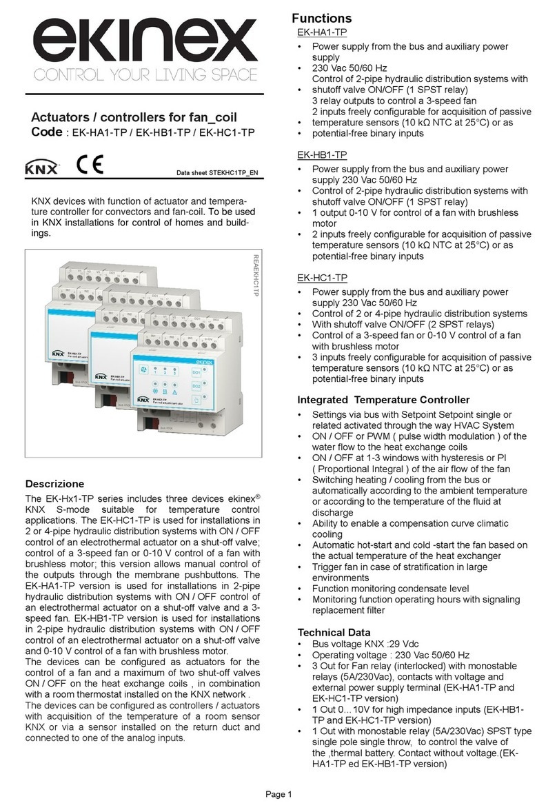
Ekinex EK-FE1-TP User manual

1
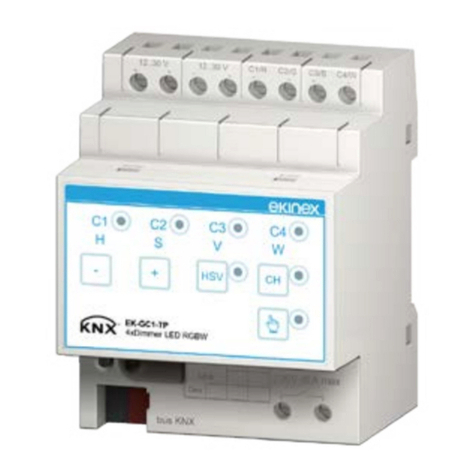
Binary output 8-fold / blind actuator 4-fold
Product code: EK-FE1-TP
pendent channels reduces to 4. In addition to the manual
control with KNX pushbuttons, the actuator can be pro-
grammed to carry out a fully automatic control depending
on information such as daytime, intensity of the solar ra-
diation, temperature, presence of rain or windspeed; such
information is contained in telegrams sent by other devi-
ces connected to the KNX bus, such as timers, sensors
or weather stations. The operation as actuator for motor
drives offers additional features.
• Complete up and down run
• Partial run with stop in position from 0 to 100 % of the
run length
• Setting of position (change during the operation of the
preset position)
• Adjustment of the slats inclination (for venetian blinds)
• Integration in scenes
• Automatic control for protection against direct sunlight
• Automatic control for protection against weather condi-
tions (wind, rain, frost)
• Locking funcion
• Forced operation
• Status feedback
The time interval between the change of direction can be
set in the planning stage through a corresponding para-
meter.
Other characteristics
• Housing in plastic material
• Mounting on 35 mm rail (according to EN 60715)
• Protection degree IP20 (installed device)
• Overvoltage class III (according to EN 60664-1)
• Classication climatic 3K5 and mechanical 3M2 (accor-
ding to EN 50491-2)
• Pollution degree 2 (according to IEC 60664-1)
• 4 modular units (1 unit = 18 mm)
• Weight 315 g
• Dimensions 72 x 90 x 70 mm (WxHxD)
KNX device for independent switching of max. 8 groups of
electrical loads (as binary output) or independent control-
ling of max. 4 drives (as blind actuator). It has to be used
in KNX installations for control of homes and buildings.
Description
The binary output / blind actuator ekinex®EK-FE1-TP is
a S-mode KNX rail mounting modular device for inde-
pendent switching electrical loads (single or groups) and
controlling motor drives for blinds. To operate the device
receives a telegram from the bus, sent by a KNX device
(such as a pushbutton, a sensor or another switching or
control device), that causes the opening or the closing of
one or more relays. The device requires an auxiliary 100-
230 Vac power supply.
Main functional characteristics
• Manual switching with membrane pushbuttons
• Status feedback of the output channels through LEDs
• Conguration as normally opened or normally closed
switch
• Logic gates and forced operation mode
• Status feedback (only at bus operating)
• Locking function for each channel
• Time programming: delay for switching on and off,
staircase lighting function with prewarning signal
• Integration in scenes
• Counter of operating hours congurable by bus
Control of blinds
The device can be used for switching and controlling
motor drives dedicated to the motion of shading systems
(such as roller shutters, blinds, curtains, etc.) or of doors,
windows or shutters. In this case, the number of inde-
Datasheet STEKFE1TP_EN
Symbol Load type Current [A]
Incandescent lamps 16(10)
Fluorescent lamps 10
Drives
(cosφ ≥ 0,6) 10
Electronic transformer for low volta-
ge incandescent lamps (e.g. halo-
gen lamps)
10
Magnetic-core transformer for low
voltage incandescent lamps (e.g.
halogen lamps)
(cosφ ≥ 0,6)
10
M
Warning! Motor drives can be damaged by sudden
and repeated changes of the direction of motion. In
order to set the correct time interval for reversing
the direction of motion, refer to the technical docu-
mentation of the drive.
!
REAEKFE1TP
Technical data
Supply
• Auxiliary power supply: 100-230 Vac 50/60 Hz
• Control section power supply: 30 Vdc control section
via KNX bus
• Current consumption from the bus <10 mA
• Power on the bus <240 mW
Outputs
• Number: 8 independent channels - 4 combined (depen-
ding on the use)
2
Connection of the KNX bus line
The connection of the KNX bus line (g. a) is made with
the terminal block (black/red) included in delivery and in-
serted into the slot of the housing.
Characteristics of the KNX terminal block
• spring clamping of conductors
• 4 seats for conductors for each polarity
• terminal suitable for KNX bus cable with single-wire
conductors and diameter between 0.6 and 0.8 mm
• recommended wire stripping approx. 5 mm
• color codication: red = + (positive) bus conductor,
black = – (negative) bus conductor
at the top.
For the installation of the device on the rail proceed as
follows:
• with the aid of a tool bring the locking device in the
fully lowered position (1);
• place the upper edge of the rear inner prole on the
upper edge of the rail (2);
• rotate the device towards the rail (3);
• push the locking device upward until it stops (4).
Before removing the device, be sure the inputs have been
disconnected and the bus terminal has been extracted
from its slot. Use a screwdriver to slide down the locking
device and remove the device from the rail.
Switching, display and connection elements
The device is equipped with a programming pushbutton
and a programming LED, membrane pushbuttons, LED
for status indication and terminals for connecting the KNX
bus line, the 100-230 Vac power supply and the outputs.
Switching elements
• Pushbutton (3) for switching between the normal and
programming operating mode
• Pushbutton (7) for switching between the operating
modes: forced (pushbuttons on the front panel: active)
or automatic (pushbuttons on the front panel: not
active)
• Pushbuttons (2) for forced operation of the output
channels
Display elements
• Red LED (4) for displaying the active operating mode
of the device (on = programming, off = normal opera-
tion)
• Green LEDs (9) for displaying the switching status of
the output channels (on = closed contact, off = opened
contact)
• Red LED (8) for displaying the operating mode (on =
forced operation, off = automatic operation)
Mounting
The device has degree of protection IP20, and is there-
fore suitable for use in dry interior rooms. The housing is
made for rail mounting according to EN 60715 in boards
or cabinets for electrical distribution. The installation is in
horizontal position, the correct position is when the KNX
bus terminal and the 100-230 Vac terminals are located at
the bottom and the terminals for the outputs are located
• Rated voltage (Un): 100-230 Vac 50 / 60Hz
• Rated current (In): max 16 (10) A (both @ 100Vac and
@ 230Vac)
• Max switched power: max 4000 VA @ 250Vac
• Inrush current: 88 A 20 ms
Environmental conditions
• Operating temperature: - 5 ... + 45°C
• Storage temperature: - 25 ... + 55°C
• Transport temperature: - 25 ... + 70°C
• Relative humidity: 95% not condensing
1 2
43
EKINSTGUIDAEKAB1TP
Warning! In order to supply the KNX bus lines use
only KNX bus power supplies (e.g. ekinex EK-AB1-
TP or EK-AG1-TP). The use of different power sup-
pliy units can compromise the communication and
damage the devices connected to the bus.
!
Note. It is recommended that the installation of the
device always ensure the full accessibility of the
front side to allow the operation of the pushbuttons.
i
1B 2B 3B 4B
1A 2A 3A 4A
EK-FE1-TP
8xD.O. 16(10)A/230Vac ~50/60 Hz
4xBlind 16(10)A/230Vac ~50/60 Hz
34
1A
A B 56
2A
A B 78
3A
A B 910
4A
A B
11 12
1B 13 14
2B 15 16
3B 17 18
4B
1 2
L N230V~ 50/60Hz
bus KNX
1) Terminal blocks for output channels
2) Pushbuttons for forced operation of the outputs
3) Programming pushbutton
4) Programming LED
5) Terminal block for KNX bus line
6) Terminal blocks for 230 Vac 50/60 Hz power supply
7) Pushbutton for switching between manual and automatic operation
8) LED for indication forced / automatic operation mode
9) LED for status indication of the outputs
1
2
4
5
8
7
6
3
9
DCEKFE1TP
Connection of the 100-230 Vac power supply
The connection of the 100-230 Vac power supply (g. a)
is made with the screw terminals located on the lower
front of the device.
Characteristics of the terminals
• screw clamping of conductors
• maximum cross section of conductor 2.5 mm²
• ecommended wire stripping approx. 6 mm
• torque max 0.5 Nm
3
Conguration
For the conguration of the device parameters the corre-
sponding application program or the whole ekinex®pro-
duct database must be loaded in the ETS program. For
detailed information on conguration options, refer to the
application manual of the device available on the website
www.ekinex.com
1B 2B 3B 4B
1A 2A 3A 4A
EK-FE1-TP
8xD.O. 16(10)A/230Vac ~50/60 Hz
4xBlind 16(10)A/230Vac ~50/60 Hz
34
1A
A B 56
2A
A B 78
3A
A B 910
4A
A B
11 12
1B 13 14
2B 15 16
3B 17 18
4B
1 2
L N230V~ 50/60Hz
bus KNX
+
L
-
N
KNX
bus
230 Vac
50/60 Hz
aConnection of the KNX bus network and 230 Vac power supply
Connection of the loads
The connection of the controlled loads (g. b, g. c) is
made with the screw terminals located at the top. In case
the device is used as 4-fold blind actuator, the terminals
must be connected coupling the channels as follows: 1A-
1B, 2A-2B, 3A-3B, 4A-4B.
Characteristics of the terminals
• screw clamping of conductors
• maximum cross section of conductor 2.5 mm² (single-
wire) or 1.5 mm² (multi-wire)
• recommended wire stripping approx. 6 mm
• torque max 0.8 Nm
Use as a blind actuator
The output contacts for the up / down directions are in-
terlocked so that no voltage is applied simultaneously on
both contacts.
Conguration and commissioning
Conguration and commissioning of the device require
the use of the ETS®(Engineering Tool Software) program
V4 or later releases. These activities must be carried out
according to the design of the building automation system
done by a qualied planner.
Product
code
Application
program
(## = release)
Communica-
tion objects
(max nr.)
Group
adresses
(max nr.)
EK-FE1-TP
APEKFE1TP##.knxprod
222 254
cConnection of the loads (device used as 4-fold blind actuator)
43 1A
1211 1B
M
L
N
65 2A
1413 2B
M
87 3A
1615 3B
M
109 4A
1817 4B
M
Warning! The electrical connection of the device
can be carried out only by qualied personnel. The
incorrect installation may result in electric shock or
re. Before making the electrical connections, make
sure the power supply has been turned off.
!
Note. The conguration and commissioning of KNX
devices require specialized skills. To acquire these
skills, you should attend the workshops at KNX cer-
tied training centers.
i
bConnection of the loads (device used as 8-fold binary output)
L
N
1A 2A
343A
564A
78
L
N
1B
11 12 2B
13 14 3B
15 16 4B
17 189 10
Warning! Sockets controlled via bus must be cle-
arly identied. Controlling loads with mobile installa-
tion (e.g. household appliances connected to mains
sockets) must be planned and realized with a care-
ful evaluation of the risks that may arise in the case
of control without direct visual contact with the load
(remote control). Connecting loads different than
those planned, remote controlling without direct ve-
rication of the current conditions of the connected
load or automatic controlling based on scenes or
time-scheduling can cause serious damage to pe-
ople and objects.
!
Commissioning
For commissioning the device the following activities are
required:
• make the electrical connections as described above;
• turn on the bus power supply;
• switch the device operation to the programming mode
by pressing the programming pushbutton located on
the front side of the housing. In this mode of operation,
the programming LED is turned on;
• download into the device the physical address and the
conguration with the ETS®program.
At the end of the download the operation of the device
automatically returns to normal mode; in this mode the
programming LED is turned off. Now the bus device is
programmed and ready for use.
4
Disposal
At the end of its useful life the product
described in this datasheet is classied
as waste from electronic equipment in
accordance with the European Direc-
tive 2012/19/UE (WEEE recast), and
cannot be disposed together with the
municipal undifferentiated solid waste.
Warning! Incorrect disposal of this product may
cause serious damage to the environment and hu-
man health. Please be informed about the correct
disposal procedures for waste collecting and pro-
cessing provided by local authorities.
Marks
• KNX
• CE: the device complies with the Low Voltage Directi-
ve (2014/35/UE) and the Electromagnetic Compatibili-
ty Directive (2014/30/UE). Tests carried out according
to EN 50491-2:2010, EN 50491-3:2009, EN 50491-4-
1:2012, EN 50491-5-1:2010, EN 50491-5-2:2010, EN
50428:2005 +A1:2007 + A2:2009
Maintenance
The device is maintenance-free. To clean use a dry cloth.
It must be avoided the use of solvents or other aggressive
substances.
Dimensions [mm]
Warnings
• Installation, electrical connection, conguration and
commissioning of the device can only be carried out
by qualied personnel in compliance with the appli-
cable technical standards and laws of the respective
countries
• The use of the device in security applications is not
allowed.The device may however be used for auxiliary
signaling functions
• Opening the housing of the device causes the imme-
diate end of the warranty period
• In case of tampering, the compliance with the essen-
tial requirements of the applicable directives, for which
the device has been certied, is no longer guaranteed
• ekinex®KNX defective devices must be returned to the
manufacturer at the following address: EKINEX S.p.A.
Via Novara 37 I-28010 Vaprio d’Agogna (NO) Italy
Other information
• This datasheet is aimed at installers, system integra-
tors and planners
• For further information on the product, please contact
the ekinex®technical support at the e-mail address:
[email protected] or visit the website www.ekinex.
com
• Each ekinex®device has a unique serial number on
the label. The serial number can be used by installers
or system integrators for documentation purposes and
has to be added in each communication addressed to
the EKINEX technical support in case of malfunctio-
ning of the device
• KNX®and ETS®are registered trademarks of KNX
Association cvba, Brussels
© EKINEX S.p.A. The company reserves the right to make changes to this
documentation without notice.
!
72
70
525 20 20
45
90
1B 2B 3B 4B
1A 2A 3A 4A
34
1A
A B
56
2A
A B
78
3A
A B
910
4A
A B
11 12
1B
13 14
2B
15 16
3B
17 18
4B
1 2
L N230V~ 50/60Hz
bus KNX
EK-FE1-TP
8xD.O. 16(10)A/230Vac ~50/60 Hz
4xBlind 16(10)A/230Vac ~50/60 Hz
DQEKFE1TP

Other manuals for EK-FE1-TP

1

Other Ekinex Controllers manuals

Ekinex EK-HA1-TP User manual

Ekinex

Ekinex EK-HA1-TP User manual

Ekinex EK-ET2-TP User manual

Ekinex

Ekinex EK-ET2-TP User manual

Ekinex EK-FF1-TP User manual

Ekinex

Ekinex EK-FF1-TP User manual

Ekinex EK-HH1-TP User manual

Ekinex

Ekinex EK-HH1-TP User manual

Ekinex KNX FF Series User manual

Ekinex

Ekinex KNX FF Series User manual

Ekinex EK-HH1-TP Instructions for use

Ekinex

Ekinex EK-HH1-TP Instructions for use

Ekinex EK-AG1-TP User manual

Ekinex

Ekinex EK-AG1-TP User manual

Ekinex EK-HE1-TP User manual

Ekinex

Ekinex EK-HE1-TP User manual

Ekinex EK-ES2-TP Instructions for use

Ekinex

Ekinex EK-ES2-TP Instructions for use

Ekinex EK-GC1-TP User manual

Ekinex

Ekinex EK-GC1-TP User manual

Ekinex KNX EK-FB1-TP User manual

Ekinex

Ekinex KNX EK-FB1-TP User manual

Ekinex 71 Series User manual

Ekinex

Ekinex 71 Series User manual

Popular Controllers manuals by other brands

phytron IXEa-A Series user manual

phytron

phytron IXEa-A Series user manual

gefran GFW-Xtra quick guide

gefran

gefran GFW-Xtra quick guide

Arcom RC210 Hardware manual

Arcom

Arcom RC210 Hardware manual

Truma DIGITAL TIMER CONTROL User instruction manual

Truma

Truma DIGITAL TIMER CONTROL User instruction manual

Woodward 505 Installation Procedure Supplement

Woodward

Woodward 505 Installation Procedure Supplement

AFRISO CosiTherm Series operating instructions

AFRISO

AFRISO CosiTherm Series operating instructions

Supreme Heating AquaGen 5 user manual

Supreme Heating

Supreme Heating AquaGen 5 user manual

Condec Orion-2C Adjustment & Maintenance Manual

Condec

Condec Orion-2C Adjustment & Maintenance Manual

SMC Networks LEJ Series Original instructions

SMC Networks

SMC Networks LEJ Series Original instructions

Zodiac iAquaLink installation manual

Zodiac

Zodiac iAquaLink installation manual

MISUMI MSCTL102 Series Operation manual

MISUMI

MISUMI MSCTL102 Series Operation manual

Mitsubishi Electric MELSEC Q Series user manual

Mitsubishi Electric

Mitsubishi Electric MELSEC Q Series user manual

Duomo BX150 manual

Duomo

Duomo BX150 manual

Smartgen ACC7200 user manual

Smartgen

Smartgen ACC7200 user manual

Extron electronics MEDIALINK MLC 206 Setup guide

Extron electronics

Extron electronics MEDIALINK MLC 206 Setup guide

White Rodgers 668 installation instructions

White Rodgers

White Rodgers 668 installation instructions

PCB Piezotronics IMI SENSORS 683A101000 Installation and operating manual

PCB Piezotronics

PCB Piezotronics IMI SENSORS 683A101000 Installation and operating manual

AMX FG2105-90 installation guide

AMX

AMX FG2105-90 installation guide

manuals.online logo
manuals.online logoBrands
  • About & Mission
  • Contact us
  • Privacy Policy
  • Terms and Conditions

Copyright 2025 Manuals.Online. All Rights Reserved.