Ekinex EK-GA1-TP Instructions for use

Application manual
KNX 2-channel Dimmer module
EK-GA1-TP

Application manual
KNX binary output modules EK-GA1-TP
Release 1.5 - Update: 02/2022 MAEKGA1TP_EN
© EKINEX S.p.A. - All rights reserved Page 2
Contents
1Scope of the document.............................................................................................................................. 4
2Product description.................................................................................................................................... 5
3Switching, display and connection elements............................................................................................. 6
4Configuration ............................................................................................................................................. 7
5Commissioning .......................................................................................................................................... 7
6Function description................................................................................................................................... 8
6.1 Power-on behaviour.............................................................................................................................. 8
6.2 Offline operation.................................................................................................................................... 9
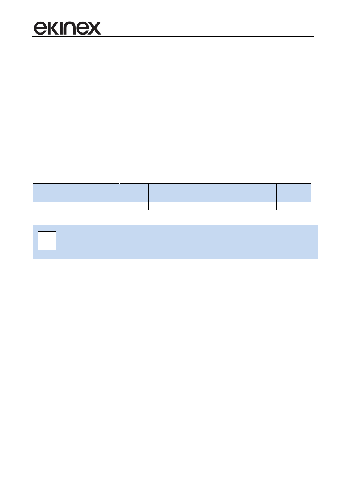
6.3 Manual operation.................................................................................................................................. 9
6.3.1 Status of the outputs across modes.............................................................................................. 9
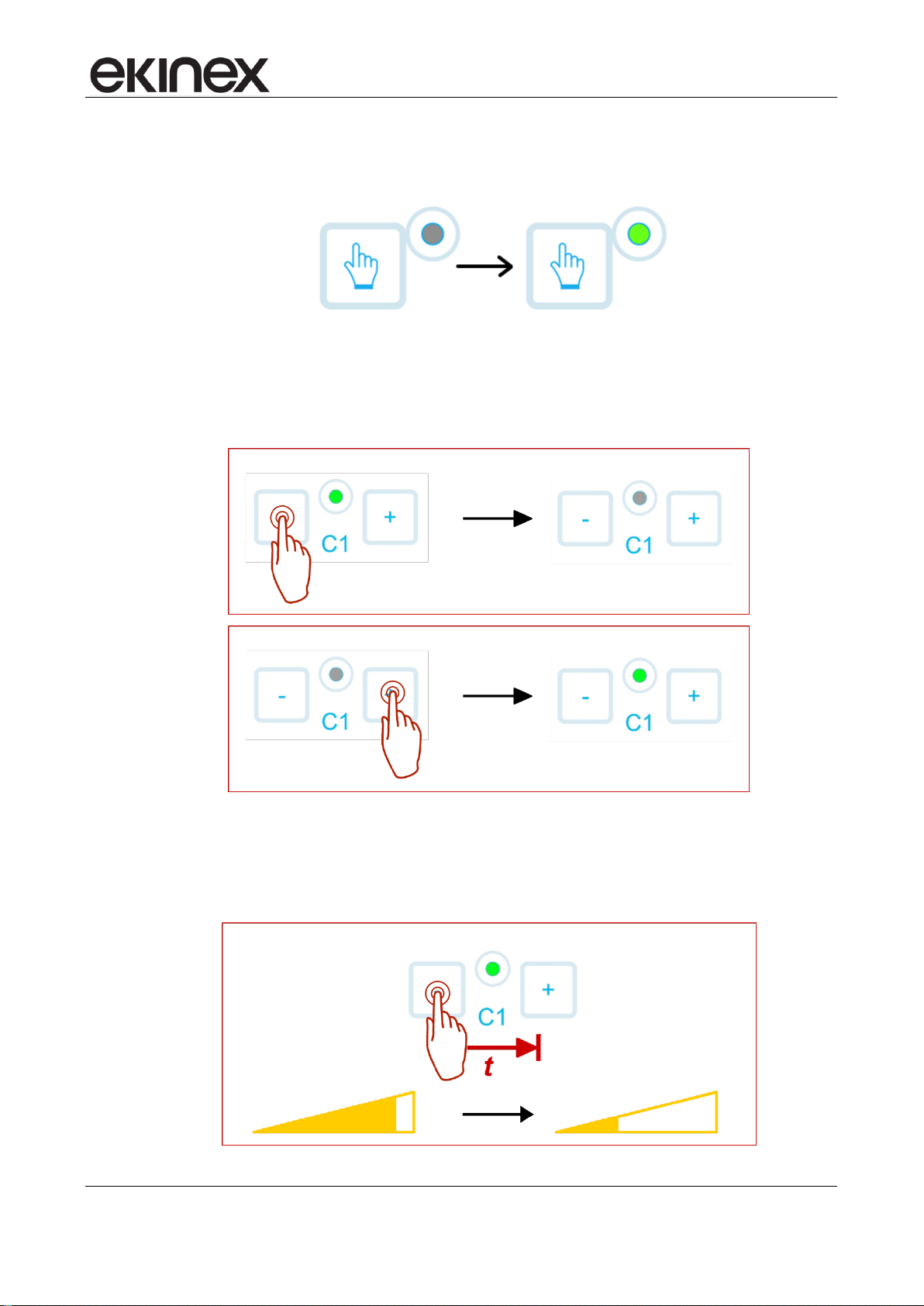
6.3.2 Activation of manual mode............................................................................................................ 9
6.4 Online operation.................................................................................................................................. 12
6.4.1 Software working cycle ............................................................................................................... 12
6.4.2 State variables (Communication objects) ................................................................................... 12
6.4.3 Output handling features............................................................................................................. 12
6.4.4 Switching feature overview ......................................................................................................... 12
6.4.5 Dimming feature overview........................................................................................................... 13
6.4.6 Functional detail.......................................................................................................................... 15
6.4.6.1 Feedback ............................................................................................................................... 15
6.4.6.2 Time delay.............................................................................................................................. 15
6.4.6.3 Staircase function................................................................................................................... 15
6.4.6.4 Logic function......................................................................................................................... 20
6.4.6.5 Lock function.......................................................................................................................... 23
6.4.6.6 Forcing function...................................................................................................................... 24
6.4.6.7 Scene management............................................................................................................... 25
6.4.6.8 Operating hours / Energy consumption counter .................................................................... 26
6.5 Device settings.................................................................................................................................... 27
6.5.1 General device configuration ...................................................................................................... 27
6.5.2 Channels configuration ............................................................................................................... 28
6.5.3 Channel x configuration .............................................................................................................. 29
6.5.3.1 Main parameters.................................................................................................................... 29
6.5.3.2 Staircase lighting function...................................................................................................... 33
6.5.3.3 Lock function.......................................................................................................................... 34
6.5.3.4 Logic function......................................................................................................................... 35
6.5.3.5 Scenes function...................................................................................................................... 36
6.5.3.6 Energy / Time counter............................................................................................................ 37
7Appendix.................................................................................................................................................. 38
7.1 Communication objects table.............................................................................................................. 38
7.2 Warning............................................................................................................................................... 41
7.3 Other information................................................................................................................................ 41

Application manual
KNX binary output modules EK-GA1-TP
Release 1.5 - Update: 02/2022 MAEKGA1TP_EN
© EKINEX S.p.A. - All rights reserved Page 3
Revision
Modifications
Author
Date
1.0
First version
G. Croci
15/07/2016
1.5
Added table for power loads
G. Schiochet
21/02/2022

Application manual
KNX binary output modules EK-GA1-TP
Release 1.5 - Update: 02/2022 MAEKGA1TP_EN
© EKINEX S.p.A. - All rights reserved Page 4
1 Scope of the document
This application manual describes all application details for the A1.0 release of the ekinex®KNX Dimmer
modules EK-GA1-TP (2 channels).
The document is aimed at the system configurator as a description and reference of device features and
application programming. For installation, mechanical and electrical details of the device please refer to the
technical description datasheet.
Application manual and application programs for ETS are available for download at www.ekinex.com.
Item
File name (## = release)
Version
Device rel.
Update
Technical datasheet
STEKGA1TP_EN.pdf
-
A1.0
02 / 2022
Application manual
MAEKGA1TP_EN.pdf
-
Application program
APEKGA1TP##.knxprod
-
You can access the most up-to-date version of the full documentation for this device using the following QR
codes:

Application manual
KNX binary output modules EK-GA1-TP
Release 1.5 - Update: 02/2022 MAEKGA1TP_EN
© EKINEX S.p.A. - All rights reserved Page 5
2 Product description
The ekinex®dimmer module EK-GA1-TP is a S-mode KNX modular device for independent switching of 2
dimmable electrical loads.
The device is equipped with an integrated bus communication module and is designed for rail mounting in
distribution boards.
For operation, the devices receives KNX telegrams from the bus, sent by another KNX device (such as a
pushbutton, a sensor, a display, a timer, etc.); these telegrams cause the activation or deactivation and
change of the dimming percentage of the loads.
The device is powered by the KNX bus line with a 30 VDC SELV voltage and does not require auxiliary
power; all required operation voltages for the input channels are produced inside the device.
For further technical information, please also refer to the product datasheet
STEKGA1TP_EN.pdf available on the ekinex website www.ekinex.com.
i

Application manual
KNX binary output modules EK-GA1-TP
Release 1.5 - Update: 02/2022 MAEKGA1TP_EN
© EKINEX S.p.A. - All rights reserved Page 6
3 Switching, display and connection elements
The device is equipped with:
a programming pushbutton and a programming LED
Membrane keys for manual operation
A membrane key to switch between manual and online mode
LED indicators for output status and for manual mode indication
terminals for input line power and output load connection
terminals for KNX bus line connection
Fig. 1 - Switching, display and connection elements
1) Terminal blocks for outputs
2) Membrane keys for manual
operation
3) LED indicators for output
status
4) LED for manual mode
indication
5) Pushbutton for switching to
manual mode
6) Programming pushbutton
7) Programming LED
8) Terminal block for KNX bus
line
9) Terminal block for input line
power

Application manual
KNX binary output modules EK-GA1-TP
Release 1.5 - Update: 02/2022 MAEKGA1TP_EN
© EKINEX S.p.A. - All rights reserved Page 7
4 Configuration
The exact functionality of the device depends on the software settings.
In order to configure and commission the device you need ETS4 or later releases and the proper ekinex®
application program APEKGA1TP##.knxprod, which can be downloaded from the ekinex®website
www.ekinex.com.
The application program allows the configuration of all working parameters for the device.
The device-specific application program has to be loaded into ETS or, as alternative, the whole ekinex®
product database can be loaded; at this point, all the instances of the selected device type can be added to
the project.
For every single device, ETS allows to set the operating parameters individually for each input as described
in detail in the following chapters.
The configuration can, and usually will, be performed completely offline; the actual transfer of the
programmed configuration to the device takes place during commissioning phase.
Product code
EAN
No. of
channels
ETS application software
(## = release)
Communication
objects
(max nr.)
Group
adresses
(max nr.)
EK-GA1-TP
8018417181214
2
APEKGA1TP##.knxprod
46
46
Configuration and commissioning of KNX devices require specialized skills. To acquire these
skills, you should attend training courses at a training center certified by KNX.
For further information: www.knx.org
5 Commissioning
After the device has been configured within the ETS project according to user requirements, the
commissioning of the device requires the following activities:
electrically connect the device, as described in the product datasheet, to the bus line on the final
network or through a properly setup network for programming;
apply power to the bus;
switch device operation to programming mode by pressing the programming pushbutton located on
the front side of the housing. In this mode of operation, the programming LED is turned on steady;
upload the configuration (including the physical address) to the device with ETS program.
At the end of the upload, the operation of the device automatically returns to normal mode; in this mode the
programming LED is turned off. Now the device is programmed and ready for use on the bus.
i

Application manual
KNX binary output modules EK-GA1-TP
Release 1.5 - Update: 02/2022 MAEKGA1TP_EN
© EKINEX S.p.A. - All rights reserved Page 8
Load type
Maximum power
Mode
Single channel
Coupled channels
Incandescent or halogen lamps
(230V~ 50/60Hz)
300 W
600 W
RC
Halogen lamps (12/24V~ 50/60Hz)
with electronic transformers
60 W
100 W
RC
Halogen lamps (12/24V~ 50/60Hz)
with magnetic transformers
60 W
100 W(*)
L
Dimmable LED lamps
(230V~ 50/60Hz)
60 W
100 W
L
120 W
200 W
RC
Dimmable LED drivers
(230V~ 50/60Hz)
60 W
100 W
RC/L
Compact Fluorescent Lamps
(ESL/CFL)
60 W
100 W
L
RC = Trailing edge
L = Leading edge
(*): DO NOT CONNECT THE TRANSFORMER WITHOUT CONNECTING THE LAMP ON THE
SECONDARY WINDING TO THE AVOID OVERVOLTAGE THAT MAY CAUSE DAMAGING TO
THE DEVICE.
6 Function description
The device is a dimming actuator, which activates its output channels according to telegrams sent by other
devices on the bus.
It also incorporates additional features such as e.g. timing and logic combination features, described in the
following chapters.
6.1 Power-on behaviour
After switching on the bus, which also acts as the main power supply, the device becomes fully functional
after a very short time needed for reinitialization; a further delay is programmable for the device to become
active on the bus in order to avoid a bus traffic overload during the first moments of startup of the whole
network.
A fully unprogrammed device causes no activity on the bus; anyway, outputs can be operated in manual
mode (see below) through the membrane key panel on the top.
In case of a bus power failure (voltage lower than 19 V for 1 s or more), the device is switched off; on power-
off, all current working values are saved.

Application manual
KNX binary output modules EK-GA1-TP
Release 1.5 - Update: 02/2022 MAEKGA1TP_EN
© EKINEX S.p.A. - All rights reserved Page 9
As soon as the bus voltage is restored, the device will resume operation in its previous, unless different
initialization settings are programmed.
The status of the device after some significant events can be defined by configuration. These events are:
Device power on, i.e. after the line power supply is applied;
Bus off, i.e. after a KNX bus failure
1
Bus on, i.e. after recovery from a KNX bus failure
Download of a new or updated configuration from ETS
Further events are associated with specific functions such as the Lock or the Forcing functions.
For each of these events, the status of the outputs can be determined from a set of values that depend on
how the output is configured; these sets of values will be listed later in the sections that describe the
corresponding functions.
6.2 Offline operation
Since the bus also acts as the power supply for the logic part of the device, a device which is not connected
to the KNX bus is effectively inoperable.
6.3 Manual operation
The manual operation works as an alternative to the output switching through bus commands (bus-controlled
mode); this mode is intended for testing or maintenance purposes.
6.3.1 Status of the outputs across modes
When manual mode is activated, the outputs can be operated using the membrane keys on the front. When
manual mode is active, however, the telegrams from the bus still influence the physical outputs.
The manual operation of the outputs on the bus does not cause the generation of any telegram status
feedback; the LEDs associated with the outputs will continue anyway to indicate their status.
At the returning in manual mode the output status remains the one currently set.
The same considerations made for the bus commands are valid for the switching due to internal timing
functions (for example delays in the activation or staircase light function): the changes of state due to internal
functions have nonetheless effect even when the manual mode is active.
6.3.2 Activation of manual mode
To switch the device to manual operation mode, proceed as follows:
1
This parameter is left in place for future expansion; currently, a bus failure causes the device to lose power
and therefore switch off.

Application manual
KNX binary output modules EK-GA1-TP
Release 1.5 - Update: 02/2022 MAEKGA1TP_EN
© EKINEX S.p.A. - All rights reserved Page 10
1) Press the manual mode pushbutton. During normal operation the LED is turned off. When the LED
turns on, the whole membrane keypad is activated and manual operation is allowed.
2) Press the pushbutton of the keypad corresponding to the desired channel and function.
A short press causes the load to be switched ON or OFF, respectively for keys “+” or “-“:
The indicator LED shows whether the load is switched ON or off.
A long press causes the output to increase or decrease according to the key pressed:

Application manual
KNX binary output modules EK-GA1-TP
Release 1.5 - Update: 02/2022 MAEKGA1TP_EN
© EKINEX S.p.A. - All rights reserved Page 11
3) When the required operation is finished, manual mode is turned off by pressing the mode pushbutton
again. Upon returning to bus-controlled mode, the output values will be restored as already
described.
Switching to manual mode through the front panel can be inhibited in two ways, both selectable through
configuration parameters:
by disabling the manual switching feature altogether;
through a bus command.
Please notice that the above-mentioned bus command inhibits switching to manual through the panel key; it
does not switch modes itself.
If manual mode is neither inhibited by configuration nor controllable through the bus, another parameter
allows setting a timeout period after which, whenever the device is left in manual mode, it will be reverted to
bus-controlled mode. This prevents the device to be inadvertently left in an unintended state.

Application manual
KNX binary output modules EK-GA1-TP
Release 1.5 - Update: 02/2022 MAEKGA1TP_EN
© EKINEX S.p.A. - All rights reserved Page 12
6.4 Online operation
The device works as a controlled switch, activating its own outputs according to the commands received
from the bus as KNX telegrams.
6.4.1 Software working cycle
The software working cycle can be described as follows:
Handle incoming telegrams from the KNX bus to update internal state variables
Implement timing functions and other inbuilt functions to determine effect on physical outputs;
Drive output relays according to output status
Respond to bus messages requesting feedback on the status of the outputs and of the device.
There are also special events on which it is possible to trigger additional features. These events are the bus
failure and recovery, and the download of a new configuration with ETS.
6.4.2 State variables (Communication objects)
The determination of the status of physical outputs is made basing on internal state variables. These state
variables, once assigned a group address, are actually KNX communication objects, which allows other
devices on the bus to exploit the features of the device.
State variables undergo the usual rules for communication objects, among which –for instance –the effect
of flags to determine how the change of value affects the transmission of the objects.
6.4.3 Output handling features
The outputs are dimmable AC channels; each channel can be driven independently.
Each output is rated for a load ranging from 10W to 300W at 230 V AC.
In the simplest case, three communication objects per channel are provided to drive the outputs:
On-Off command, that switches each channel output directly
Dimming command, that modifies the dimming percentage of a channel in an incremental way, i.e.
with “up / down / stop” type commands
Absolute setpoint control, that allows to directly specify the absolute dimming percentage.
One communication objects per channel is provided as a feedback:
Actual dimming value, that returns the current value of the dimming percentage.
6.4.4 Switching feature overview
By setting the device parameters, it is possible to activate additional features, most of which will also affect
outputs. These features are:
Feedback: sends message on each On –Off switching operation or cyclically each period of time
Time delay block: allows to perform the actual switch with a programmable delay. It is available (with
separate delay settings) both for the On-Off and for the Off-On transition.
Staircase function: performs a retriggerable time period activation of an output.
Logic function: allows to compute the output value as a logic function based on the value of several
communication objects.

Application manual
KNX binary output modules EK-GA1-TP
Release 1.5 - Update: 02/2022 MAEKGA1TP_EN
© EKINEX S.p.A. - All rights reserved Page 13
Lock and Force: these functions can temporarily force the output to fixed values and also perform
high priority switching operations.
Scene management: - allows to save and recall a combination of state and values with a single
telegram.
Operating hours / Energy consumption counter: allows a limited tracking of energy consumption by
accumulating “On” period durations over time.
The most significant functional blocks are described in the following scheme.
Fig. 2 - Functional blocks
The above functions are mostly, but not all purely digital (i.e. related to an On-Off behaviour); for instance,
the scene management involves the definition of the brightness level associated with the scene. More details
can be found in the function description in following paragraphs.
6.4.5 Dimming feature overview
Further parameters are available, which are more closely related to the dimming function:
Type of electrical load (necessary to operate the dimming power stages properly and with optimum
regulation)
Dimming increase / decrease speed
Dimming value lower limit, to ensure that the “On” state has sufficient brightness
Brightness value at switch-on
Type of transition and dimming speed both at switch-on and switch-off.

Application manual
KNX binary output modules EK-GA1-TP
Release 1.5 - Update: 02/2022 MAEKGA1TP_EN
© EKINEX S.p.A. - All rights reserved Page 14

Application manual
KNX binary output modules EK-GA1-TP
Release 1.5 - Update: 02/2022 MAEKGA1TP_EN
© EKINEX S.p.A. - All rights reserved Page 15
6.4.6 Functional detail
6.4.6.1 Feedback
When the feedback is enabled, 2 communication objects are available for reading by other devices on the
bus: an object indicates the current state of ON / OFF, the other object indicates the current percentage of
dimming. These objects report the actual state of the logic output, which is probably different from that set by
the command, as it includes the effect of any other functions currently active.
When these communication objects are defined, they are transmitted automatically at any status change, so
that events can be generated at any actual change of the output. It is also possible to configure the objects,
so that the transmission also takes place at regular intervals.
When the power-on and / or power-off mode are set to soft, the communication object that
indicates the current position of dimming provides as feedback the actual value that will reach at
the end of the ramp. Similarly during dimming, the final value (maximum or minimum) is provided
as feedback and, only after the release of the dimming command, the dimming percentage
actually achieved is provided as feedback.
6.4.6.2 Time delay
The actual change of state of an output can be set to take place after a configurable delay from the change
of the value of the corresponding communication object; this applies both to the on-off and the off-on
transitions, each with its individually configurable delay value (Ton and Toff respectively).
These delays are applied to the transitions through a direct command and/or logical objects, but not to those
caused by other functions (e.g.: staircase or scene).
Fig. 3 - Time delay
6.4.6.3 Staircase function
This function is intended to provide a simple and flexible way to manage the switching of staircase lights.
These have following peculiar requirements:
i

Application manual
KNX binary output modules EK-GA1-TP
Release 1.5 - Update: 02/2022 MAEKGA1TP_EN
© EKINEX S.p.A. - All rights reserved Page 16
The light is activated by a “start” command (e.g. through a pushbutton or a presence sensor), and
normally remain lit for a programmed time duration;
There is a provision to enable a “stop” (Manual Off) command, again through a pushbutton or other
events, that allows to switch the light off before the programmed time expires (e.g. because the
person who triggered the presence sensor has surely left the building through an exit);
There is a provision to allow another “start” command (Retriggering), received during activation, to
restart the time duration counter;
A further optional “pre-warning” function allows to briefly switch off the load a certain time before
expiration (both times, i.e. pause duration and time before expiration, are configurable) in order to
warn the user that the activation time is about to end.

Application manual
KNX binary output modules EK-GA1-TP
Release 1.5 - Update: 02/2022 MAEKGA1TP_EN
© EKINEX S.p.A. - All rights reserved Page 17
Following pictures show the Manual Off feature:
Fig. 4 - Manual Off feature

Application manual
KNX binary output modules EK-GA1-TP
Release 1.5 - Update: 02/2022 MAEKGA1TP_EN
© EKINEX S.p.A. - All rights reserved Page 18
Following pictures show the Retrigger feature:
Fig. 5 - Retrigger feature

Application manual
KNX binary output modules EK-GA1-TP
Release 1.5 - Update: 02/2022 MAEKGA1TP_EN
© EKINEX S.p.A. - All rights reserved Page 19
Following pictures show the Pre-warning feature:
Fig. 6 - Pre-warning feature

Application manual
KNX binary output modules EK-GA1-TP
Release 1.5 - Update: 02/2022 MAEKGA1TP_EN
© EKINEX S.p.A. - All rights reserved Page 20
6.4.6.4 Logic function
The device has a limited provision for the logic processing of internal variables in order to condition the
status of outputs.
A given incoming output command can be used as an input to a logic block which operation is selectable
between OR, AND and XOR (exclusive OR). Up to other 8 objects can be defined as additional inputs to the
same block (each with an optional negation operation); these objects are directly accessible to other devices
from the bus and they can be used as desired.
The input objects are logically combined as in following picture:
Fig. 7 - Logic functions
The logic combination block on the right works as follow according to which logical operation is selected:
OR –the output is ON whenever any one of the inputs is ON;
AND –the output is ON only if all of the inputs are ON;
XOR –the output is ON if an ODD number of inputs are ON.
This latter operation is more intuitive when thinking of two inputs only: in this case, the output is ON
when one input or the other is ON, but not both.
It must be noted that, in the above description, “input” and “output” are referred to the logical block; for the
purpose of operation, the actual “inputs” are the logic objects, thus the optional inverters must be factored in.
This structure allows to implement complex logical combinations; a more generic and powerful programming
capability would add more complexity and therefore it would be far beyond the scope of an output module
that is simple to use.
In the following pictures, the basic logic functions are illustrated, assuming the output command and one
logic object are used:
Table of contents
Other Ekinex Dimmer manuals

Ekinex
Ekinex EK-GD2-TP-1-HV User manual

Ekinex
Ekinex EK-GD1-DL-4-HV User manual

Ekinex
Ekinex EK-GO1-DL User manual

Ekinex
Ekinex EK-GH1-DL User manual

Ekinex
Ekinex EK-GD2-TP-1-HV Instructions for use

Ekinex
Ekinex EK-GM2-DL User manual

Ekinex
Ekinex KNX 90-230 Operating and safety instructions

Ekinex
Ekinex EK-GL1-DL User manual