3
INSTALLATION TECHNICAL NOTES
• Installation and maintenance must be
performed only if the power supply has
been turned o.
• Installation and maintenance must only
be performed by qualied personnel in
compliance with current regulations.
• The product must be installed inside
an electrical panel protected from over-
voltages.
• The product must be protected by a sui-
tably sized fuse.
• The product must be protected by a sui-
tably sized magnetothermic switch.
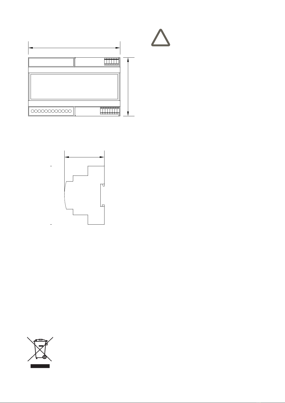
• The product must be installed in a verti-
cal position with the front / label facing
the front or in a horizontal position with
the front / label facing upwards. Other
product installation positions are not al-
lowed. The bottom position with the front
panel / label facing down is not allowed.
• Use in thermally harsh environments
could limit the output power.
• Keep 230V circuits (LV) and non-SELV
circuits separate from SELV circuits with
very low safety voltage
!
Conguration and commissioning
Conguration and commissioning activities of the device
must be carried out according to the design of the building
automation system done by a qualied planner.
For commissioning the device the following activities are
required:
• make the electrical connections as indicated above;
• power up the bus;
• carry out the device addressing, which can be done in
two ways:
1. simplied method: by connecting one ballast at a
time, each one will get the address progressively
from 0 to 63;
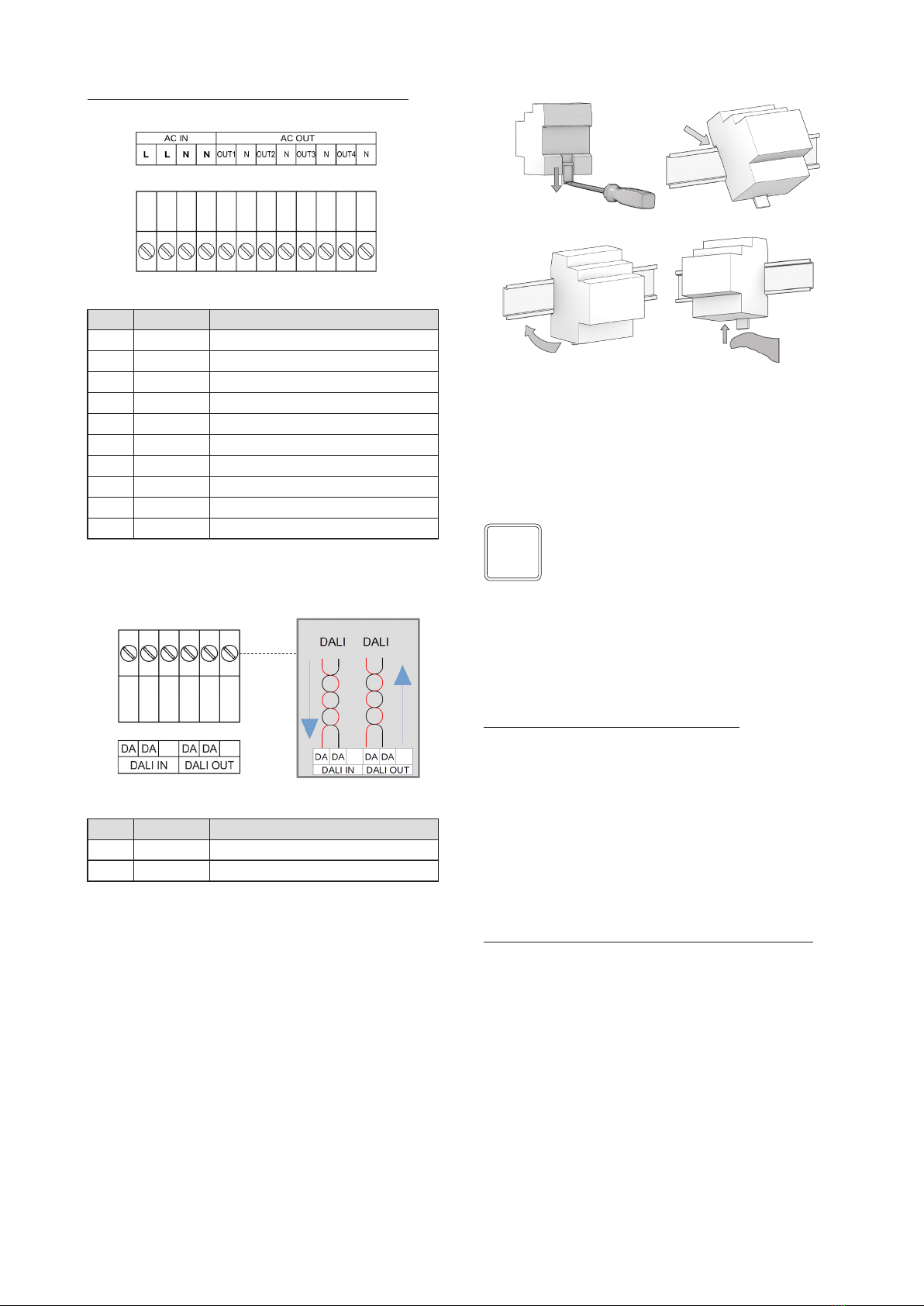
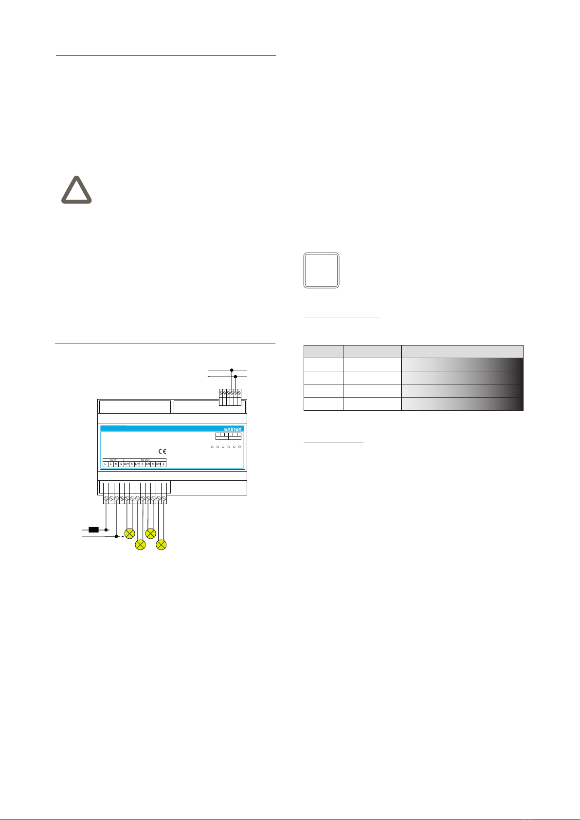
Installation scheme
230 Vac
50-60 Hz +
DALI
FUSE
AC Dimmer
EK-GO1-DL
Input: 230V ~ 50Hz
Output: 230V ~
Load: 4x 200W max
DALI IN
DA DA DA DA
DALI OUT
OUTPUT
1234
BUS PWR
2. random address allocation: by connecting all the bal-
lasts at the same time, each one will get a random
address.
Subsequently, the address conguration can be changed
by using an application for parameterization, for example
by downloading the ekinex CGEKBG1TP software to your
PC which allows to:
• congure the DALI system and dene its parameters;
• set the DALI luminaires (groups, scenarios, IDs, etc.);
• test the communication on the DALI bus;
• update the device.
The software can be downloaded from www.ekinex.com
website and its use is described in the application manual
of the ekinex EK-BG1-TP DALI Gateway. The software
requires Microsoft Windows (7 and later).
Address Function Dimmer map
0 Dimmer 1 Dimmer (Intensity Value) 0 ... 254
1 Dimmer 2 Dimmer (Intensity Value) 0 ... 254
2 Dimmer 3 Dimmer (Intensity Value) 0 ... 254
3 Dimmer 4 Dimmer (Intensity Value) 0 ... 254
DALI channel maps
Type of load: single color up to 4 loads
Signaling LEDs
On the front of the device there are 6 signaling LEDs:
• 1-2-3-4 for each channel
• BUS for trac indication on the DALI bus
• PWR to indicate that the device is powered on
If the BUS is not supplied or there is a BUS error, the rela-
tive signaling LED ashes quickly (2 pulses per second).
If the BUS is supplied but there is a BUS error, the relative
signaling LED ashes slowly (1 pulses per second).
If the BUS is connected and it is working properly, the
LED remains on steady.
Note. In order to install and use the CGEKBG1TP
conguration software, it could be necessary the
installation of .NET Framework 4, which can bee
freely downloaded from Microsoft.com website.
i