4
Conguration and commissioning
Conguration and commissioning activities of the device
must be carried out according to the design of the building
automation system done by a qualied planner.
For commissioning the device the following activities are
required:
• make the electrical connections as indicated above;
• power up the bus;
• carry out the device addressing, as described in the
next paragraphs.
Local command
Depending on the local control, the device can manage
dierent functions on the output loads.
Push dimmer
The intensity and the status change (ON/OFF) are con-
trolled by a N.O. pushbutton.
ded – 16 - 17 AWG
• Conductor stripping recommended: 5.0 - 6.0 mm
• Maximum length of the connection between dimmer-
driver and control device < 10 m
• Length of connection cables < 10 m
Connection of power supply and LEDs
For the power supply use SELV power suppliers with li-
mited current, short circuit protection only and the power
must be correctly dimensioned. In case of usage of a po-
wer supplier with ground terminals, all points of the pro-
tective earth (PE = Protection Earth) must be connected
to a valid and certied protection earth.
The connection cables between the power source “low
voltage” and the product must be correctly dimensioned
and they should be isolated from every wiring or parts at
not-SELV voltage. Use double insulated cables.
The power supply must be dimensioned according to
the load connected to the device. If the power supply is
oversized with respect to the maximum absorbed current,
then insert a protection against over-current between the
power supply and the device.
Characteristics of the supply and LEDs terminal block
• Screw tightening of the conductors
• Power & LEDs wiring: 1.5 mm2solid – 1.0 mm2stran-
ded – 16 - 17 AWG
• Power and LEDs stripping recommended approx.: 5.0
- 6.0 mm
• Max torque 0.5 Nm
Outputs
The length of the connection cables between the product
and the LED module must be less than 10 m; the cables
must be correctly dimensioned and they should be isola-
ted from every wiring or parts at not-SELV voltage. It is
preferable to use shielded and twisted cables.
In case it is needed to connect the device and LED mo-
dules with cables longer than 10m, the installer must gua-
rantee the correct functioning of the system. In any case,
do not exceed 30 m of the connection between the device
and the LED modules.
Button function Intensity
Click ON / OFF
Double click Maximum intensity
Long press (> 1 s) from OFF Turn ON at 1% (Nightly function), then
dimmer UP / DOWN
Long press (> 1 s) from ON Dimmer UP / DOWN
15 clicks in 5 seconds timeframe Enter PUSH MENU
0-10V, 1-10V or potentiometer
The dimming intensity is managed by tuning the input vol-
tage.
Button function Intensity
0-10V Dimmer: 0V = 0% - 10V = 100%
1-10V Dimmer: 1V = 0% - 10V = 100%
Potentiometer 10 kΩ Dimmer: continuous regulation 0-100%
Automatic detection of the local command type
At the rst switch on, the device is set by default to auto-
matic recognition of N.O. push button command.
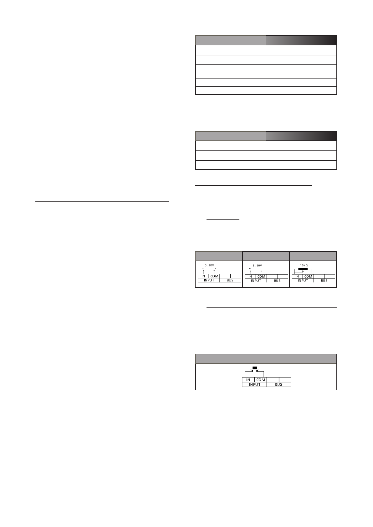
• Automatic detection of 0-10V, 1-10V and potentiome-
ter command
The automatic recognition of analog signal 0/1-10V or
potentiometer starts as soon as either a 0/1-10V value
between 3V and 7V is sent out, or by setting the potentio-
meter with value included from 30% and 70%.
0-10 V command 1-10 V command Potentiometer
• Automatic detection of the N.O. pushbutton com-
mand
The N.O. pushbutton is identied automatically after 5
clicks in rapid sequence.
In N.O. pushbutton mode, the memory function is always
active.
N.O. pushbutton
Push menu
In the LED dimmer menu, the following functions are avai-
lable:
• minimum dimming value setting;
• power-on ramp (fade in) setting;
• power-o ramp (fade oou) setting.
Access to menu
When the LED dimmer is turned on, the output is set at
100% and the minimum dimming value at 1%. To access
the device menu, perform a sequence of 15 clicks over a
period of 5 seconds.