Ekinex EK-GH1-DL User manual

1
REFLEKGH1DL
DALI 1-channel dimmer
Code: EK-GH1-DL
Outputs
• Output voltage = input voltage
• Output current: max 8 A peak, max 7,5 A @55°C, max
6,5 A @60°C
• Nominal power @12V: 78 W (@6,5A) – 90W (@7,5A)
• Nominal power @24V: 156 W (@6,5A) – 180W (@7,5A)
• Nominal power @48V: 312 W (@6,5A) – 360W (@7,5A)
• Thermal shutdown: 150 °C
• Command supply current: 0,5mA (for 1-10V)
• Command required current (max): 0,1mA (for 0-10V)
DALI bus dimmer with 12/24/48 Vdc power supply, it pro-
vides LED sources brightness control function. Dimming
can can be managed by using dierent types of comman-
ds: KNX buttons or other local control devices.
Datasheet STEKGH1DL_EN
SNote: the values for output current have to be inten-
ded as maximum values, depending on the ventila-
tion conditions.
i
Description
The ekinex DALI 1-channel dimmer EK-GH1-DL allows
brightness control of dimmable LED sources by means of
several kinds of button. It can be connected by means of
KNX (TP) pushbutton connected to a DALI / KNX Gate-
way or via another command device, directly connected
to the dedicated input, selectable from a normally open
button, 0-10V analog input, 1-10V analog input and 10 kΩ
potentiometer. The device has an integrated DALI bus
communication modules voltage and requires a 12, 24 o
48 Vdc input power supply.
Functional characteristics
• Constant voltage dimmer
• DALI bus command
• Number of channels: 1
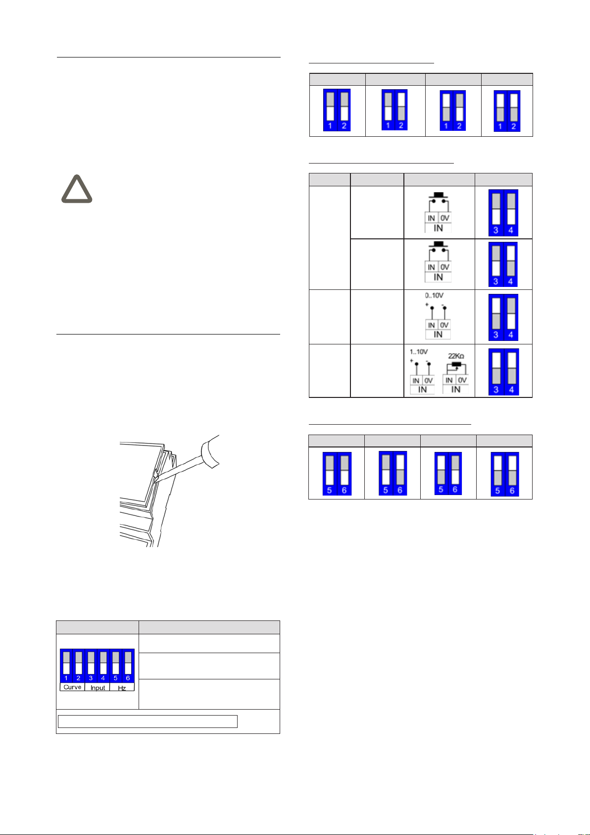
• Local command: N.O. pushbutton / analog input 0-10V
/ 1-10V / 10 kΩ Potentiometer
• Brightness adjustment for LED loads
• Voltage output for R-L-C loads
• Typical eciency > 95%
• Brightness adjustment up to full o (Dim to Dark)
• Minimum brightness level: 0.1% (1% in push)
• D-PWM Modulation
• Adjusting D-PWM frequency: 300 / 600 / 1200 Hz
• Adjusting output curve: Linear / Quadratic / Exponential
• Soft start and soft stop
Technical data
Inputs
• Input (constant voltage): 12 / 24 / 48 Vdc
• Supply voltage: min: 10,8 Vdc .. max: 52,8 Vdc
• Power absorbed while awaiting command: <500 mW
Dimming
• Dimming frequency D-PWM: 300Hz – 600Hz – 1200Hz
• Resolution D-PWM: 16 bit
• Dimming range D-PWM: 0,1-100%
Environmental conditions and other characteristics
• Operating temperature: -40 ° C ... + 60 ° C
• Storage temperature: - 40 ° C ... + 60 ° C
• Transport temperature: - 40 ° C ... + 60 ° C
• Relative humidity: 93% non-condensing
• Protection degree IP10 (device installed)
• Command & bus wiring: 1.5 mm2solid – 1 mm2stran-
ded – 30-14 AWG
• Power & LEDs wiring: 2.5mm2solid – 1.5 mm2stranded
– 30-12 AWG
• Command & bus stripping: 6 mm
• Power and LEDs stripping: 7.5 mm
• Housing in plastic material
• Safety class II
• Weight 67 g
• Modular device 2 MU (1 MU = 18 mm)
• Dimensions 91 x 36 x 62 mm (LxHxP)
Protections
The device is provided with the following protections:
• OTP Over temperature protection1
• OVP Over voltage protection2
• UVP Under voltage protection2
• RVP Reverse polarity protection2
• IFP Input fuse protection2
• SCP Short circuit protection
• CLP Current limit protection
1) Thermal Protection on the output channel in case of high temperature. The thermal
intervention is detected by transistor (>150°C).
2) Control logic protection only
Control, signaling and connection elements
The device is equipped with a screw terminal for connec-
ting the 12 / 24 / 48 Vdc input power supply and the output
loads (1), a screw terminal for connecting the local com-
mands and the DALI line (2) and one signaling LED (3).

2
Terminal blocks for connection of inputs and outputs
Mounting
The device has degree of protection IP10, and is there-
fore suitable for use in dry interior rooms. The housing is
made for rail mounting according to EN 60715 in boards
or cabinets for electrical distribution. The correct mounting
is when the DC inputs screw terminal is located at the bot-
tom. When installing be sure to leave accessible only the
front panel; all other sides must not be accessible. For the
mounting proceed as follows:
• with the aid of a tool bring the locking device in the fully
lowered position (a);
• place the upper edge of the rear inner prole on the
upper edge of the rail (b);
• rotate the device towards the rail (c);
• push the locking device upward until it stops (d).
Note. When mounting the device in boards and ca-
binets it shall be provided the necessary ventilation
so that the temperature can be kept within the ope-
rating range of the device.
i
a b
dc
1) Screw terminal for 12/24/48 Vdc input and output loads
2) Screw terminal for local commands and DALI line connection
3) Signalling LED
--
OUT
L-
Dimmer LED
EK-GH1-DL
DC In: 12-48V
Out: max 8A
DALI IN
DA DA DA DA
DALI OUT
1
2
3
Nr. Mark Connection
1-3 + DC (+) input
2-4 - DC (-) input
5 L+ Output (+)
6 L- Output (-)
Nr. Mark Connection
1-2 INPUT IN-0V N.O. Pushbutton input, analogic input or
potentiometer
3 DA-DALI IN DALI pole 1
6 DA-DALI OUT
4 DA-DALI IN
DALI pole 2
7 DA-DALI OUT
5-8 - Not used
Before removing the device, be sure that inputs, outputs,
and the DC power supply have been disconnected. Use a
screwdriver to slide down the locking device and remove
the device from the rail.

3
INSTALLATION TECHNICAL NOTES
• Installation and maintenance must be
performed only if the power supply has
been turned o.
• Installation and maintenance must only
be performed by qualied personnel in
compliance with current regulations.
• The product must be installed insi-
de an electrical panel protected against
overvoltages.
• The product must be installed in a verti-
cal position with the front / label facing
the front or in a horizontal position with
the front / label facing upwards. Other
product installation positions are not al-
lowed. The bottom position with the front
panel / label facing down is not allowed.
• Keep separated the circuits at 230V (LV)
and the circuits not SELV from circuits
to low voltage (SELV) and from any con-
nection with this product. It is absolutely
forbidden to connect, for any reason
whatsoever, directly or indirectly, the
230V mains voltage to the bus or to other
parts of the circuit.
!
Setup and installation
In order to setup the dip-switch, it is necessary to open
the device front cover, by means of a screwdriver as de-
tailed in the image below.
Conguration Settings
Switch 1-2 = dimming curve
Switch 3-4 = input type
Switch 5-6 = Output Frame Rate –
Frequency
Note: Factory settings = ALL OFF
Switches 1-2 (dimming curve settings)
Default Exponential Quadratic Linear
Switches 3-4 (input local command settings)
Command Description Connection Conguration
Pushbutton
N.O. pushbutton
without memory
N.O. pushbutton
with memory
0 - 10 V
Analog input
0-10V
1 - 10 V
Analog input
1-10V
or
Potentiometer
Switches 5-6 (output dimming frequency settings)
300 Hz 600 Hz 1200 Hz Reserved
DALI bus line and command connections
The connection to the DALI bus network and the local
commands is done via the screw terminal, located on the
front of the device in the upper part.
The length of the connection cables between the local
commands (N.O. Pushbutton, 0-10V, 1-10V, Potentiome-
ter or other) and the product must be less than 10m; the
cables must be dimensioned correctly and they should be
isolated from every wiring or parts at voltage not SELV.
Use double insulated shielded and twisted cables.
The length and type of the connection cables to the DALI
bus must be compliant with the protocol specication and
with the present regulations and they should be isolated
from every wiring or parts at voltage not SELV. Use dou-
ble insulated shielded and twisted cables.
All the devices and the control signal connected to the
DALI bus and to the local command (N.O. Pushbutton,
0-10V, 1-10V, Potentiometer or other) must be SELV (the
devices connected must be SELV or supply a SELV si-
gnal).
The 6-way dip-switch setting (under the front cover) oers
a wide choice of possible congurations.

4
Conguration and commissioning
Conguration and commissioning activities of the device
must be carried out according to the design of the building
automation system done by a qualied planner.
For commissioning the device the following activities are
required:
• make the electrical connections as indicated above;
• power up the bus;
• carry out the device addressing, as described in the
product Datasheet and in the application manual.
Device addressing
• Simplied method: 1 ballast connected at a time
• Random Address Allocation
DALI channels maps
The intensity and ON / OFF switching of the output is ma-
naged via the DALI channel.
Characteristics of the DALI terminal block
• Screw tightening of the conductors
• Command & bus wiring: 1.5 mm2 solid – 1 mm2 stran-
ded – 30 - 14 AWG
• Command & bus stripping: 6 mm
• Conductor stripping recommended approx. 10 mm
• Maximum length of the connection between dimmer-
driver and control device < 10 m
• Length of connection cables < 10 m
Connection of power supply and LEDs
For the power supply use SELV power suppliers with li-
mited current, short circuit protection only and the power
must be correctly dimensioned. In case of usage of a po-
wer supplier with ground terminals, all points of the pro-
tective earth (PE = Protection Earth) must be connected
to a valid and certied protection earth.
The connection cables between the power source “low
voltage” and the product must be correctly dimensioned
and they should be isolated from every wiring or parts at
not-SELV voltage. Use double insulated cables.
The power supply must be dimensioned according to
the load connected to the device. If the power supply is
oversized with respect to the maximum absorbed current,
then insert a protection against over-current between the
power supply and the device.
Characteristics of the supply and LEDs terminal block
• Screw tightening of the conductors
• Power & LEDs wiring: 2. 5mm2 solid – 1.5 mm2 stran-
ded – 30 - 12 AWG
• Power and LEDs stripping recommended approx.: 7.5
mm
• Max torque 0.5 Nm
Outputs
The length of the connection cables between the product
and the LED module must be less than 10m; the cables
must be correctly dimensioned and they should be isola-
ted from every wiring or parts at not-SELV voltage. It is
preferable to use shielded and twisted cables.
In case it is needed to connect the device and LED mo-
dules with cables longer than 10m, the installer must gua-
rantee the correct functioning of the system. In any case,
do not exceed 30m of the connection between the device
and the LED modules.
SUPPLY
+
L N
230 Vac
12-48 Vdc
DALI
50-60 Hz
--
OUT
L-
+
Dimmer LED
EK-GH1-DL
DC In: 12-48V
Out: max 8A
DALI IN
DA DA DA DA
DALI OUT
Installation scheme
Address Function Map: dimmer
0 Dimmer Dimmer (Intensity value) 0 .. 254
Signalling LEDs
On the device front panel a signaling LED is present. If
there is no BUS power supply or there is a BUS error,
the signaling LED ashes quickly (2 pulses per second).
If there is BUS power supply but a BUS error occurs, the
signaling LED ashes slowly (1 pulse per second). If the
BUS signal is connected and working correctly, the LED
remains on steady.
Relationship between DALI bus and local commands: on
power-up, in case the bus connection is not present, the
local command is active. When the BUS connection is
detected, the control passes to the BUS as long as the
signal is present. In the absence of the signal, if the local
command is an N.O. button, the control is passed to the
local commands when the button is pressed. On the other
hand, if the local command is 0-10V or 1-10V, the control
immediately passes to the local command.

5
Warning! Incorrect disposal of this product may
cause serious damage to the environment and hu-
man health. Please be informed about the correct
disposal procedures for waste collecting and pro-
cessing provided by local authorities.
!
Local commands
Available functions:
N.O. pushbutton with memory / N.O. pushbutton without memory.
Light dimming by following the selected regulation
curve and by keeping the color temperature constant.
Soft start with 200ms fade time. Soft switch-off with
a fade time of 1s.
• Click: Switch ON / OFF
• Double Click: max. intensity (100%)
• Long press (>1s) while OFF: switch ON at 1%
(Night function)
• Long press (>1s) while ON: Dimming UP /
DOWN
Available functions: 0-10V / 1-10V / potentiometer.
Light dimming by following the selected regulation
curve and by keeping the color temperature constant.
Min. intensity = 0,1%
• < 1 V: load OFF
• 10 V: max. intensity
Dimensions [mm]
108
91.00
36
62
108
91.00
36
62
Marks
• CE: the device complies with the Electromagnetic
Compatibility Directive (2014/30/EU) and the RoHS 2
Directive (2011/65/UE).
• Reference Standards: EN
61347-1:2008+A1:2011+A2:2013, EN 61000:2014-
3.2, EN 61000:2013-3.3, EN 62384:2006+A1:2009,
EN 55015:2013+A1:2015 , EN 61547:2009, EN
50581:2012
Maintenance
The device is maintenance-free. To clean use a dry cloth.
It must be avoided the use of solvents or other aggressive
substances.
Disposal
At the end of its useful life the product
described in this datasheet is classied
as waste from electronic equipment in
accordance with the European Directive
2012/19/EU (WEEE recast), and cannot
be disposed together with the municipal
undierentiated solid waste.
Warnings
• Installation, electrical connection, conguration and
commissioning of the device can only be carried out by
qualied personnel in compliance with the applicable
technical standards and laws of the respective countri-
es
• Opening the housing of the device causes the imme-
diate end of the warranty period
• In case of tampering, the compliance with the essential
requirements of the applicable directives, for which the
device has been certied, is no longer guaranteed

6
• ekinex® defective devices must be returned to the ma-
nufacturer at the following address: Ekinex S.p.A. Via
Novara 35, I-28010 Vaprio d’Agogna (NO) Italy
Other information
• The instruction sheet must be delivered to the end cu-
stomer with the project documentation
• For further information on the product, please contact
the ekinex® technical support at the e-mail address:
com
• Each ekinex® device has a unique serial number on
the label. The serial number can be used by installers
or system integrators for documentation purposes and
has to be added in each communication addressed to
the EKINEX technical support in case of malfunctio-
ning of the device
• KNX® and ETS® are registered trademarks of KNX As-
sociation cvba, Brussels
© EKINEX S.p.A. The company reserves the right to make changes to this
documentation without notice.
Table of contents
Other Ekinex Dimmer manuals

Ekinex
Ekinex EK-GD2-TP-1-HV User manual

Ekinex
Ekinex EK-GD2-TP-1-HV Instructions for use

Ekinex
Ekinex EK-GA1-TP Instructions for use

Ekinex
Ekinex EK-GL1-DL User manual

Ekinex
Ekinex EK-GO1-DL User manual

Ekinex
Ekinex EK-GD1-DL-4-HV User manual

Ekinex
Ekinex KNX 90-230 Operating and safety instructions

Ekinex
Ekinex EK-GM2-DL User manual