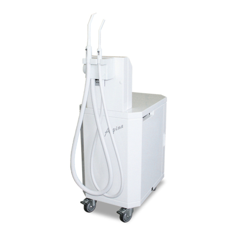
EKOM ASPINA DO M User manual

ASPINA - DO M
User manual
EN
Benutzerhandbuch
DE
N
Manuel de l’utilisateur
FR
Návod na použitie
SK
Руководство пользователя
RU
Návod k použití
CS
Instrukcja obsługi
PL


THE DENTAL ASPIRATOR
DENTALE ABSAUGEINHEIT
L’ASPIRATEUR DENTAIRE
ДЕНТАЛЬНОЕ ОТСАСЫВАЮЩЕЕ УСТРОЙСТВО
ODSYSARKA DENTALNA
DENTÁLNA ODSÁVAČKA
DENTÁLNÍ ODSÁVAČKA
ASPINA - DO M
EKOM spol. s r. o.
Priemyselná 5031/18
SK-921 01 Piešťany
Slovak Republic
tel.: +421 33 7967255
fax: +421 33 7967223
www.ekom.sk
email: ekom@ekom.sk
DATE OF LAST REVISION
DATUM DER LETZTEN ÜBERARBEITUNG
DATE DE MISE A JOUR
ДАТА ПОСЛЕДНЕГО ПЕРЕСМОТРА
DATA WYDANIA
DÁTUM POSLEDNEJ REVÍZIE
DATUM POSLEDNÍ REVIZE
10/2020
NP-DO M-37_10-2020
112000080-000

CONTENTS........................................ 5
INHALT ............................................ 22
SOMMAIRE...................................... 40
ОГЛАВЛЕНИЕ................................. 58
SPIS TREŚCI ................................... 76
OBSAH ............................................ 93
OBSAH ...........................................110

INSTALLATION –OPERATION –MAINTENANCE ASPINA - DO M
NP-DO M-37_10-2020 - 5 -
CONTENTS
IMPORTANT INFORMATION............................................................................................... 6
1. WARNINGS................................................................................................................6
1.1. CE Marking................................................................................................................ 6
1.2. General warnings....................................................................................................... 6
1.3. General safety warnings........................................................................................... 6
1.4. Safety warnings regarding the protection against electric current .............................. 6
1.5. Alert notices and symbols.......................................................................................... 7
2. PRODUCT INFORMATION ........................................................................................8
2.1. Intended Use............................................................................................................. 8
2.2. Contraindications and side-effects............................................................................. 8
2.3. Product Description ................................................................................................... 8
3. TECHNICAL DATA.....................................................................................................9
3.1. FAD efficiency correction for differences in elevation................................................. 9
3.2. Electromagnetic compatibility declaration .................................................................10
4. FUNCTION DESCRIPTION......................................................................................13
4.1. Function Description.................................................................................................13
4.2. Detailed Description of the Suction Part Function.....................................................13
ASSEMBLY.........................................................................................................................13
5. STORAGE AND TRANSPORT CONDITIONS..........................................................13
6. INSTALLATION AND INITIAL START-UP ................................................................14
6.1. Environmental Conditions.........................................................................................14
6.2. Electric Connection...................................................................................................14
6.3. Initial Start-ip.............................................................................................................14
USE......................................................................................................................................15
7. OPERATION.............................................................................................................15
7.1. Switching on the Dental Aspirator.............................................................................15
7.2. Use of antifoaming tablets ........................................................................................15
7.3. Filter use in the separation vessel.............................................................................15
8. MAINTENANCE INTERVALS - USER / TECHNICIAN..............................................16
9. MAINTENANCE, CLEANING AND DISINFECTION .................................................16
9.1. Inlet Sieve Cleaning..................................................................................................17
9.2. Lubricating seals and sliding closures.......................................................................17
9.3. Disinfection of Tubings and Separation Vessel.........................................................17
9.4. Cleaning and disinfection of the exterior surfaces of the product ..............................17
9.5. Replacement of the Output Pre-filter.........................................................................17
9.6. Replacement of Output Filter....................................................................................18
9.7. Cannulas handling and preparation operation...........................................................18
9.8. Replacing the filter in the separation vessel..............................................................19
10. PUTTING OUT OF OPERATION..............................................................................19
DISPOSAL...........................................................................................................................19
11. DISPOSAL OF APPLIANCE.....................................................................................19
TROUBLESHOOTING.........................................................................................................20
12. INFORMATION ON REPAIR SERVICE....................................................................20
13. SOLVING COMMON PROBLEMS............................................................................20
ANNEXES..........................................................................................................................126
14. WIRING DIAGRAMS...............................................................................................126
15. FUNCTION DIAGRAM............................................................................................128
16. ENCLOSURE NO. 1 ...............................................................................................129
17. INSTALLATION RECORD......................................................................................130

ASPINA-DO M INSTALLATION –OPERATION –MAINTENANCE
- 6 - NP-DO M-37_10-2020
IMPORTANT INFORMATION
1. WARNINGS
1.1. CE Marking
Products marked with CE mark of compliance meet requirements of European Union directives
(93/42/EEC).
1.2. General warnings
The installation, operation and maintenance manual is an integral part of the appliance. It is
necessary to always keep this document close to the appliance. Strict observance of this manual
is a prerequisite for the correct operation of the appliance.
The safety of operating personnel and failure-free operation of the appliance are ensured only
when using the original components of the appliance. It is possible to use accessories and spare
parts mentioned in the technical documentation or clearly permitted by the manufacturer.
When used with non authorized accessories or consumable material, the manufacturer cannot
assume responsibility for the safe operation and functionality of the device.
The Guarantee does not cover damages that originate due to the use of non authorized
accessories or consumable material other than those recommended by the manufacturer.
The manufacturer assumes responsibility regarding safety, reliability and function only if
-The installation, calibration, amendments, extensions and repairs are made by the
manufacturer or his representative or a service organization authorized by the manufacturer,
-The appliance is used in accordance with the installation, operation and maintenance
manual.
The installation, operation and maintenance manual, at the time of printing, corresponds to the
design of the appliance and its state according to the relevant safety and technical standards.
The manufacturer reserves all copyrights for the given wiring schemes, methods and names.
This user manual is the original instructions. Translation is performed in accordance with the best
available knowledge.
1.3. General safety warnings
The manufacturer developed and constructed the appliance so that damage would not occur when
the appliance is used for its intended purpose. The manufacturer considers it his obligation to
describe the following safety measures in order to avoid further damages.
When operating the appliance, it is necessary to observe laws and regional regulations valid in
the place of usage. In order to ensure safe course of works, the operator and user are responsible
for the observation of regulations.
The original packaging should be kept for the possible return of the unit. Only original packaging
guarantees an optimal protection of the appliance during transportation. If it would be necessary
to return the appliance during warranty period, the manufacturer is not responsible for damages
caused by incorrect packing.
It is necessary that the user ensures the appliance is safe to use prior to usage.
The user must familiarize himself with the correct operation of appliance.
If an undesirable event occurs in the operation of appliance, the user is obliged to immediately
inform his supplier to this event.
This product is not intended for use in areas with the risk of explosion.
1.4. Safety warnings regarding the protection against electric current
The appliance must only be connected toan appropriate power sourcethat has correct grounding.
Prior the connecting the compressor, verify whether the mains voltage and frequency specified
on the equipment are in accordance with the local supply.
Prior to putting into operation, check for possible damages on the appliance and the air
connectors. Damaged cables and sockets/plugs must be replaced immediately.

INSTALLATION –OPERATION –MAINTENANCE ASPINA - DO M
NP-DO M-37_10-2020 - 7 -
In the case of a dangerous situation or a technical failure, immediately disconnect the appliance
from mains supply.
During all repairs and maintenance:
-ensure that the mains plug is removed from the power socket
-pressure pipes must be air vented
-pressure must be released from pressure tank.
This appliance can only be installed only by a qualified expert.
1.5. Alert notices and symbols
For your information, the symbols below are used in the installation, operation and maintenance
manual, on packaging materials and on the product :
General warnings
Warning
Danger, electric shock hazard.
Read the operating instructions
Refer to instruction manual
CE –marking
Attention! Hot surface.
Handling mark on package –FRAGILE
Handling mark on package –THIS SIDE UP
Handling mark on package –KEEP DRY
Handling mark on package –TEMPERATURE LIMITATIONS
Handling mark on package –LIMITED STACKING
Mark on package –RECYCLABLE MATERIAL
Connection of protective ground wire
Fuse
Danger of biological hazard
Indicates a medical device that has not undergone sterilization

ASPINA-DO M INSTALLATION –OPERATION –MAINTENANCE
- 8 - NP-DO M-37_10-2020
Sterilizable in a steam sterilizer (autoclave) at specified temperature
Manufacturer
2. PRODUCT INFORMATION
2.1. Intended Use
The dental aspirator ASPINA DO M is a mobile equipment extending the possibilities of procedures
provided for by a physician and ensuring the increase of ergonomy at his work. It is suitable for the
dental units not equipped with the suction equipment and a separator. It is intended for the dental
practice needs for aspiration, separation and entrapping of the waste into the built-in separation
vessel. With regard to its mobility it enables a simple transport between the workplaces and can be
used above all where the connection to a sewerage system is impossible.
The dental aspirator is designed for the operation in dry, ventilated rooms, with the ambient
temperature ranging between +5°C up to +40°C, and relative humidity not exceeding the value of
70%.
The dental aspirator may not be exposed to rain. The equipment may not be operated in the
moist or wet environs. In addition, avoid the use near gases or combustible liquids.
Other use, or the use exceeding this scope, can not be regarded as the intended use. The
maufacturer is not responsible for the resulting damages. The risk will be born exclusively by the
operator / user.
2.2. Contraindications and side-effects
There are no contraindications or side-effects known.
2.3. Product Description
(Annex No.1)
The mobile dental aspirator ASPINA DO M is built-up on a movable bogie on which is situated a box,
lined by a noise damping material. Inside the box there is situated a fan cooled suction aggregate
(9) with the electric distribution and the waste entrapping separation vessel (11). In the lower part –
under the box –there is situated a silencer with an output filter (14) and a pre-filter (15) ensuring the
air filtration from the suction aggregate. In the upper –narrowed part of the aspirator - there is
situated a holder for suction tubings (2) equipped with cannulas (1), separation automatics and
therminal boxwith fuses. On the lateral part there is situateda main switch (5), over which are placed
the indicators for the network (3) and for the state of filling of the separation vessel (4).

INSTALLATION –OPERATION –MAINTENANCE ASPINA - DO M
NP-DO M-37_10-2020 - 9 -
3. TECHNICAL DATA
DO M
Rated voltage / frequency
V / Hz
230 / 50; 230 / 60*;
110 / 60*
Nominal current
A
2.6
maximum flowrate :
l/min
1100
maximum underpressure
kPa
12
Sound level
dB(A)
48
Mode of operation of the aspirator
permanent
S 1
Dimensions of the aspirator
mm
565x350x860
Dimensions of the aspirator with carton
(h x w x d)
mm
950x560x595
Weight of the apirator
kg
36
Weight of the aspirator with
Carton
kg
40
Model according to
STN EN 60 601-1 (IEC 60601-1)
equipment type B, class I
Classification pursuant to MDD 93/42/EEC,
2007/47/EC
IIa
(*) The rated voltage and frequency can be change by special order
Climatic conditions for the operation:
Temperature +5°C up to 40°C
Relative air humidity up to +70%
3.1. FAD efficiency correction for differences in elevation
FAD correction table
Elevation [mamsl]
0 - 1500
1501 - 2500
2501 - 3500
3501 - 4500
FAD [l/min]
FAD x 1
FAD x 0.8
FAD x 0.71
FAD x 0.60
FAD efficiency refers to conditions at an elevation of 0 mamsl:
Temperature: 20°C
Atmospheric pressure: 101325 Pa
Relative humidity: 0%

ASPINA-DO M INSTALLATION –OPERATION –MAINTENANCE
- 10 - NP-DO M-37_10-2020
3.2. Electromagnetic compatibility declaration
Medical equipment needs special precautions regarding electromagnetic compatibility (EMC) and
needs to be installed and put into service according to the EMC information provided below.
Guidance and manufacturer's declaration - electromagnetic emissions
Pursuant to IEC 60601-1-2:2014 - Medical electrical equipment - Part 1-2: General requirements for
basic safety and essential performance - Collateral Standard: Electromagnetic disturbances
The equipment is intended for use in the electromagnetic environment specified below. The customer or the
user of the equipment should assure that it is used in such an environment.
Emissions test
Compliance
Electromagnetic environment - guidance
RF emissions CISPR 11
Group 1
The equipment uses RF energy only for its
internal functions. Therefore, the RF emissions
are very low and are not likely to cause any
interference in nearby electronic equipment.
RF emissions CISPR 11
Class B
The equipment is suitable for use in all
establishments, including domestic
establishments and those directly connected to
the public low voltage power supply
network that supplies buildings used for
domestic purposes.
Harmonic emissions IEC
61000-3-2
Class A
Voltage fluctuations/
flicker emissions IEC
61000-3-3
The equipment is not
likely to cause any flicker,
as the current flow is
approx. constant after the
start up.

INSTALLATION –OPERATION –MAINTENANCE ASPINA - DO M
NP-DO M-37_10-2020 - 11 -
Guidance and manufacturer's declaration - electromagnetic immunity
Pursuant to IEC 60601-1-2:2014 - Medical electrical equipment - Part 1-2: General requirements for
basic safety and essential performance - Collateral Standard: Electromagnetic disturbances
The equipment is intended for use in the electromagnetic environment specified below. The customer or the
user of the equipment should assure that it is used in such an environment.
Immunity test
IEC 60601-1-2
test level
Compliance level
Electromagnetic environment -
guidance
Electrostatic
discharge (ESD)
IEC 61000-4-2
±8 kV contact
±15 kV air
±8 kV contact
±15 kV air
Floors should be wood, concrete
or ceramic tile. If floors are covered
with synthetic material, the relative
humidity should be at least 30%.
Electrical fast
transient/burst
IEC 61000-4-4
±2 kV for power
supply
lines
±1 kV for
input/output lines
±2 kV
100 kHz repetition
frequency
Applied to mains
connection
Mains power quality should be
that of a typical commercial or hospital
environment.
Surge
IEC 61000-4-5
±1 kV differential
mode
±2 kV common
mode
±1 kV L-N
±2 kV L-PE; N-PE
Applied to mains
connection
Mains power quality should be that of
a typical commercial or hospital
environment.
Voltage dips,
short interruption,
and voltage
variations on
power
supply
input lines IEC
60601-4-11
UT=0%, 0,5 cycle
(at 0, 45, 90, 135,
180, 225, 270
and 315°)
UT=0%, 1 cycle
UT=70% 25/30
cycles (at 0°)
UT=0%, 250/300
cycles
UT=>95%, 0,5 cycle
(at 0, 45, 90, 135, 180,
225, 270 and 315°)
UT=>95%, 1 cycle
UT=70% (30% dipp
UT),
25(50Hz)/30(60Hz)
cycles (at 0°)
UT=>95%,
250(50Hz)/300(60Hz)
cycle
Mains power quality should be
that of a typical commercial or hospital
environment.
The device stops and restarts
automatically at each dip. In this case
does not occur unacceptable pressure
drop.
NOTE: UTis the A.C. mains voltage prior to application of the test level.

ASPINA-DO M INSTALLATION –OPERATION –MAINTENANCE
- 12 - NP-DO M-37_10-2020
Guidance and manufacturer's declaration - electromagnetic immunity
Pursuant to IEC 60601-1-2:2014 - Medical electrical equipment - Part 1-2: General requirements for
basic safety and essential performance - Collateral Standard: Electromagnetic disturbances
The equipment is intended for use in the electromagnetic environment specified below. The customer or the
user of the equipment should assure that it is used in such an environment.
Immunity test
IEC 60601-1-2
test level
Compliance level
Electromagnetic environment - guidance
Conducted RF
IEC 61000-4-6
Radiated RF
IEC 61000-4-3
Proximity fields
from RF wireless
communications
equipment
IEC 61000-4-3
3 Vrms
150 kHz to 80MHz
3 V/m
80 MHz to 2,7
GHz
9 to 28 V/m
15 specific
frequencies
(380 to 5800 MHz)
3 Vrms
3 V/m
9 to 28 V/m
15 specific
frequencies
(380 to 5800
MHz)
Portable and mobile RF communications
equipment should be used no closer to any
part of the equipment, including cables,
than the recommended separation distance
calculated from the equation applicable to
the frequency of the transmitter.
Recommended separation distance
d=1,2√ P
d=1,2√ P, 80 MHz to 800 MHz
d=2,3√ P, 800 MHz to 2,7 GHz
where P is the maximum output power
rating of the transmitter in watts (W)
according to the transmitter manufacturer
and d is the recommended separation dis-
tance in metres (m).
Field strengths from fixed RF transmitters,
as determined by an electromagnetic site
survey a, should be less than the
compliance level in each frequency range b.
Interference may occur in the vicinity of
equipment marked with the following
symbol:
NOTE 1 At 80 MHz and 800 MHz, the higher frequency range applies.
NOTE 2 These guidelines may not apply in all situations. Electromagnetic propagation is affected by
absorption and reflection from structures, objects and people.
aField strengths from fixed transmitters, such as base stations for radio (cellular/cordless) telephones and
land mobile radios, amateur radio, AM and FM radio broadcast and TV broadcast cannot be predicted
theoretically with accuracy. To assess the electromagnetic environment due to fixed RF transmitters, an
electromagnetic site survey should be considered. If the measured field strength in the location in which
the equipment is used exceeds the applicable RF compliance level above, the equipment should be
observed to verify normal operation. If abnormal performance is observed, additional measures may be
necessary, such as re-orienting or relocating the equipment.
bOver the frequency range 150 kHz to 80 kHz, field strengths should be less than 3 V/m.

INSTALLATION –OPERATION –MAINTENANCE ASPINA - DO M
NP-DO M-37_10-2020 - 13 -
4. FUNCTION DESCRIPTION
4.1. Function Description
After switching-on the main switch (5) into the position „I“ the network indicator (3) goes on. Taking
the suction tubing (6) off the holder (2) will actuate the suction aggregate (9) and the underpressure
occurs at the suction mouthpiece (1). After repeated putting the suction tubing into the holder, the
suction aggregateturns off. When the separation vessel (11) is filled with waste products, the suction
aggregate turns off and the indicator for the separation vessel (4) filling goes on. Then it is necessary
to return the suction tubing back into the holder and to empty the separation vessel. During a longer
work, mainly with the desalivating mouthpiece, the box temperature may increase; the cooling fan is
then automatically actuated. The fan turns off automatically, when the box temperature drops
4.2. Detailed Description of the Suction Part Function
The underpressure air flows together with sucked waste products from the oral cavity through the
tubing system from the suction mouthpiece (1) at first through the inlet sieve (7), wherein the solid
impurities are entrapped. The underpressure air, together with the sucked waste products, free of
solid impurities greater than 2 mm, then flows into the separation vessel (11) wherein it is separated
from the underpressure air and entrapped into the separation vessel.
Suction air flows through the filter (18) and into the suction unit (9), from which it is pushed through
a noise muffler. Therein the output air passes through the output pre-filter (15) and the bacteriologic
output filter (14). After passing the filters, the air free of impurities is blown off into a free space under
the dental aspirator.
ASSEMBLY
5. STORAGE AND TRANSPORT CONDITIONS
The dental aspirator is delivered ex-work packed in a transport carton, preventing the equipment
from being damaged during the transport.
For the transport, always use an original product packing, if possible.
Transport the dental aspirator in an upright position.
Protect the aspirator during transport against moisture, impurity or extreme temperatures.
The aspirator in an original packing can be stored in warm, dry and dustfree rooms.
Keep the packing material for possible future return shipments. If this is not possible,
dispose the packing material in an environmental-friendly way. The transport carton can
be disposed off as the old paper.
Mobile dental aspirator may only be transported with emptied separation vessel.
Always empty the separation vessel contents before any transport.
Storing or shipping the equipment in any conditions other than those specified
below is prohibited.
Climatic conditions for the storage and transport
Temperature –25°C up to +55°C, 24 h up to +70°C
Relative air humidity 10% up to 90 % (without condensation)

ASPINA-DO M INSTALLATION –OPERATION –MAINTENANCE
- 14 - NP-DO M-37_10-2020
6. INSTALLATION AND INITIAL START-UP
Before the initial start-up, remove all locking means serving for fixing the equipment
during the transport.
First actuation can be done only by professional specialist.
ANY MODIFICATION OF THIS EQUIPMENT IS FORBIDDEN!
This equipment cannot be used nearby other instruments. If this equipment is used
nearby other instruments, the equipmentmust be observed in order toverify normal
operations in the configuration it will be used.
Instruments may be affected electro-magnetically!
6.1. Environmental Conditions
The equipment may only be installed and operated in dry, well ventilated and dust-free rooms.
The mobile dental aspirator should be installed with regard to an easy access for the operation
and maintenance and good accessible rating plate.
The equipment should stand on a plane, sufficiently stable base (be aware of the aspirator
weight, see item 3. Technical data).
Neither the lines for the connection to the electric network, nor the suction tubings
may be cranked.
To guarantee a trouble-free operation of the aspirator, the room temperature should never drop
under +5˚C and exceed +40°C. The ideal ambient temperatures are between +10°C up to +25°C.
Most of the electric energy used by the suction aggregate (9) is converted to heat and given off
to the ambient. During a longer lasting work, above all with the desalivating mouthpiece, the box
temperature increases over 40°C causing an automatic actuation of the cooling fan. After the
room is cooled down under approximately 32°C, the fan turns off again.
6.2. Electric Connection
The dental aspirator model 230V is delivered with the safety plug. It is unavoidable to observe the
rules of the local electricity works. The network voltage and frequency must be in compliance with
the rating plate data.
In case that the equipment is fix connected to the supply of electric voltage, a disconnecting
device must be situated near the equipment.
If the equipment is connected to the supply of electric voltage by means of a plug, the socket
must be good accessible for safety reasons, so that the equipment can safely be unplugged from
the network in case of a danger.
The network distribution must be protected by maximum 10 A.
The power cord can only be replaced by maintenance personnel!
6.3. Initial Start-ip
After unpacking, put the aspirator on the floor, open the door and check whether the separator’s
cover (10) with sensing electrodes is attached to the separation vessel (11). In case of need, fix the
cover to the vessel and then follow the instructions in the Chapter No. 9. Close the door and connect
the aspirator’s power cord to the socket. Change the main switch (5) over into the position “I”, the
indicating lamp for the network (3) goes on and the aspirator is ready for the operation.
Suction cannulas must comply with local legislative and technical requirements for
dental suction cannulas and their connection dimensions must be compatible with
suction cannulas connectors of 11mm and 16mm diameter

INSTALLATION –OPERATION –MAINTENANCE ASPINA - DO M
NP-DO M-37_10-2020 - 15 -
Cannulas are not delivered in a sterile state!
Suction cannulas must undergo complete preparation cycles before first use and
after each patient or use following instructions in Chapter 9.7
USE
7. OPERATION
The equipment may only be operated by the trained staff!
Disconnect from the network in case of a danger (unplug) ! Hot surfaces of the
suction aggregate. Do not touch - Danger of burn.
7.1. Switching on the Dental Aspirator
Switch on the dental aspirator by turning the power-supply switch (5) in the position „I“.
The aspirator is put into operation automatically by taking the suction tubing (6) with a mouthpiece
(1) off the holder (2). It works uninterruptedly until both tubings are put on the holders again or until
the separation vessel (11) is full (during an uniform operation it is filled within about 6 –10 hours).
Suction tips holder is equipped with vacuum regulation of suction unit depends on dentist needs.
The state of filling of the separation vessel is evaluated by the separation automatics which interrupts
the suction by the aggregate (9) and filling of the separation vessel is indicated automatically with
the indicator lamp (4) going on. At this point it is necessary to put the tubings with suction
mouthpieces into the holder and switch the power-supply switch off. Afterwards open the door by
pulling the grips situated on the side walls, uncouple rubber fixing lugs from the separator cover (10)
and pull the separator’s vessel out. Hang the separator’s cover into the holder on the left side (8).
Empty the separation vessel content into the sewer, rinse the vessel with water, connect with the
separator’s cover in a reversal order. Set the separator into a bowl (12) in the aspirator box (the bowl
is detachable). Check the connection of the cover with the vessel, seating of the separation vessel
in the bowl and close the door.
7.2. Use of antifoaming tablets
Under specific exhaust conditions, increased exhaust condensate foaming may occur due to the
switching off of the exhaust unit when the separation tank is not full. Antifoaming tables (17) must
be inserted in order to prevent this from occurring (see the basic accessories); add these tables to
the intake screen (7). The tablets will then gradually dissolve in the input screen and will significantly
decrease exhaust condensate foaming; the tablets also function as disinfection agents.
7.3. Filter use in the separation vessel
The filter in the separation vessel is an additional layer of protection for the suction unit to prevent
moisture from the foam from entering the suction unit. Foam is generated in the separation vessel
under specific suction conditions. Foam-blocking tablets are used to eliminate such foam, see
Chapter
Schedule for adding tablets: Insert 1 or 2 antifoaming tablets into the intake screen (7) at the end
of work and after cleaning and disinfecting the equipment.
Suction cannulas must undergo complete preparation cycles before first use and
after each patient or use following instructions in Chapter 9.7
Used suction cannulas intended for repeated use must be cleaned and steam
sterilized after every patient (see Chapter 9.7).
The cannulas are to be exchanged after maximum of 100 cycles of steam sterilizing.
Cannulas must be visually inspected for any signs of wear or tear before they are
used. -Never use the cannulas if it is damaged: discard it immediately.

ASPINA-DO M INSTALLATION –OPERATION –MAINTENANCE
- 16 - NP-DO M-37_10-2020
It´s forbidden to cover all blow-holes placed on upper sides of unit.
Aspirator contains no spare power supply!
Before each switch on running unit it´s neccessary to check if door of box is closed.
8. MAINTENANCE INTERVALS - USER / TECHNICIAN
Notice!
The operating entity is obliged to ensure that all tests of the equipment are carried out
repeatedly at least once within every 24 months (EN 62353) or in intervals as specified by the
applicable national legal regulations. A report must be prepared on the results of the tests
(e.g.: according to EN 62353, Annex G), including the measurement methods used.
Maintenance to be done
Chapter
Time interval
To be
performed
by
Use of antifoaming tablets
7.2
at need
user
Inlet Sieve Cleaning
9.1
per day
user
Lubricating seals and sliding
clamps
9.2
Every 15 days
User
Disinfection of Tubings and
Separation Vessel
9.3
per day
user
Cleaning and disinfection of the
exterior surfaces of the product
9.4
at need
user
Replacement of output pre-filter
9.5
every 3 months
user
Replacement of output filter
9.6
per annum
user
Exchange of suction cannula
9.7
max. 100 steam cleaning
cycles
user
Replacing the filter in the
separation vessel
9.8
Every 18 months
User
Perform “Repeated Test”
according to EN 62353
8
1x in 2 years
qualified
technician
9. MAINTENANCE, CLEANING AND DISINFECTION
Repair works exceeding the scope of a general maintenance may only be carried
out by a qualified specialist or by the maufacturer’s customer service.
Use only spare parts and accessories permitted by the maufacturer.
Before making any maintenance, repair or cleaning, it is unavoidable to disconnect
the equipment from the network (unplug).
Allow the equipment to cool down before maintenance and service!
Reconnect the grounding lead if removed during service work to its previous
location once the work is complete.
During the preparation phase for suction cannulas, always wear EC marked
personal protective equipment (PPE).

INSTALLATION –OPERATION –MAINTENANCE ASPINA - DO M
NP-DO M-37_10-2020 - 17 -
Following works must be carried out from the hygiene and the correct aspirator function points of
view.
9.1. Inlet Sieve Cleaning
Solid particles (sucked together with a liquid component and the air) are entrapped in the inlet sieve
(7) during the equipment operation (Enclosure No. 1, Fig. 1) which therefore must be regularly
cleaned, by section 8 (though, always at the end of each shift).
The inlet sieve cleaning is possible only after the moisture inside suction tubings (6) and a sieve is
reduced by means of the several seconds lasting air suction through tubings taken off the holder (2).
Then turn the power-supply switch (5) off in the position „O“ and slightly lift the cover of the inlet
sieve. Afterwards pull the sieve out of its place gripping the holder, remove solid particles and clean
the sieve. Then put the sieve on the previous place into the holder and carry out the assembly in the
contrary manner to the dismantling.
If the suction of amalgam particles is expected, it is necessary to empty the inlet sieve content into
a closing vessel and forward it to the collecting centres.
9.2. Lubricating seals and sliding closures
O-rings (sealing rings) and sliding terminal clamps(Enclosure No. 1- pos.1)must be lubricated using
a suitable silicone oil for dental applications (e.g. Lubri-Jet spray) every 15 working days.
9.3. Disinfection of Tubings and Separation Vessel
For the separation vessel (11) disinfection it is necessary to empty the same, rinse with warm water
and clean mechanically with warm water and a disinfectant.
The disinfection of internal suction tubings and of the separation vessel should be performed by
section 8, though always at the end of a shift by suction of warm water containing a disinfectant
having a limited foaming power through both suction tubings (6) separately. The used disinfectant
must be approved in compliance with a valid national legislation on usage for disinfected surface
and a type of material. For the disinfectant use, follow the maufacturer’s instructions.
9.4. Cleaning and disinfection of the exterior surfaces of the product
Use neutral agents for cleaning and disinfection of the external surfaces of the product.
The use of aggressive cleaning agents and disinfectants comprising alcohol and
chlorides may lead to the damage of the surface and the discoloration of the
product.
To find out whether the aspirator works correctly, the following works should be carried out in the
defined maintenance intervals:
9.5. Replacement of the Output Pre-filter
It is necessary to replace the output pre-filter (15) by section 8. Before making any replacements
turn the aspirator power-supply switch (5) off. The pre-filter together with the filter (14) are situated
on the left lower part of the aspirator’s bogie having the symbol .
For its dismantling, catch the filter holder (13) with one hand and with the other hand slew the fixing
lugs (16) by 90° by simultaneous pulling down. Remove the filter holder together with the output
filter. Then release the output pre-filter from the cavity wherein also the output filter was situated
(check also the state of pollution of the output filter).
For the reassembly, set the output filter into the filter holder, put the output pre-filter onto the filter
(direct the output pre-filter with the gummed cloth towards the filter) and insert all the assembly into
the cavity space from below. Slew the fixing lugs back by 90° so that they engage into the recessed
parts of the filter holder.

ASPINA-DO M INSTALLATION –OPERATION –MAINTENANCE
- 18 - NP-DO M-37_10-2020
9.6. Replacement of Output Filter
During the regular use of the device, the output filter (14) must be replaced according to the interval
in Chapter 8. The procedure of disassembly and assembly of the filter is the same as for the
replacement of output prefilter (15).
9.7. Cannulas handling and preparation operation
The preparation instructions have been drafted by supplier of cannulas in accordance with EN ISO
17664 standard requirements.
During the preparation phase for suction cannulas, always wear EC marked
personal protective equipment (PPE).
TYPE /
MANUFACTURER OF
CANNULAS
DELIVERED FOR THE
PRODUCT
Type: Monoart aspirator tips EM21 22910103, Monoart aspirator tips
EM21 EVO 22931001
Euronda, Via Chizzalunga 1, 36066 Sandrigo, VI, Italia
Tel.(+39) 0444 656185
www.euronda.com
WARNINGS
Store brand new or unused cannulas in a dry, clean and protected
environment
Only use EC marked detergents and disinfectants, suitable for use
with polypropylene (PP), following the indications concerning
concentration, temperature and time of action provided in the
manufacturer´s instructions.
Collect and clean the cannulas immediately after use. Dried or
sticky residue can make cleaning operations difficult or ineffective.
Never use metal brushes to clean such products.
Damaged cannulas must not be reused.
TRANSPORTATION
AFTER USE
Place the product in a specific container with disinfectant solution
according to the concentrations and soak times indicated by the
manufacturer.
PREPARATION FOR
CLEANING
If necessary, remove visible dirt from the product and then rinse
under running water.
MANUAL CLEANING
Use a nylon brush and detergent/disinfectant, suitable for use with
polypropylene (PP), to clean the product until all dirt has been
removed. Use a bottle brush to clean the insides.
Rinse thoroughly under running water (of good microbiological
quality) until all detergent/disinfectant residue has been removed.
Dry well using compressed air.
ULTRASONIC
CLEANING
Place the product in a perforated basket and place it inside the
ultrasonic bath filled with detergent or a disinfectant solution
suitable for polypropylene (PP).
Set the wash cycle following the manufacturer´s instructions; it is
not recommended to set the temperature above 45°C.
Rinse thoroughly under running water (of good microbiological
quality) until all detergent residue has been removed.
Check there is no dirt residue on the product; repeat the cleaning
cycle whenever necessary.
Dry well using compressed air.
Note: ultrasonic cleaning can be used in conjunction with manual and
automatic cleaning and disinfection.
THERMAL
DISINFECTOR
CLEANING
Use cleaning and disinfectant equipment that is EN ISO 15883
standard-compliant.
Position the product using the supplied holders so that the water
flows easily and rinses the inner surfaces.

INSTALLATION –OPERATION –MAINTENANCE ASPINA - DO M
NP-DO M-37_10-2020 - 19 -
Follow the manufacturer´s instructions concerning selection of
cleaning/disinfection cycles and detergents to be used.
On completing the cycle, check there is no dirt residue on the
product; repeat the cleaning cycle whenever necessary.
OPERATING CHECKS
AND INSPECTION
Visually inspect the condition and cleanliness level of the product.
Discard all damaged or worn products.
PACKAGING
Select EC marked packaging that meets the requirements of Council
Directive 93/42/CEE and addenda, suitable for the product and the
sterilization procedure, leaving enough space to prevent tension
when sealed.
STEAM
STERILIZATION
Fractionated pre-vacuum steam sterilization using EN 13060 or EN
285 standard compliant equipment and validated sterilization
procedure in accordance with EN ISO 17665-1 standard
requirements.
Use type B cycles.
Sterilization temperature: 134°C.
Stay time: 5 minutes.
Dry time: 10 minutes.
MAXIMUM DURATION
100 cycles
STORAGE
Storage times shall depend on the type of packaging used and the
storage environment. Packaging must be protected against dust,
humidity and all contamination risks.
9.8. Replacing the filter in the separation vessel
1
2
3
10. PUTTING OUT OF OPERATION
When the dental aspirator is not used for a longer time, it is necessary to carry out the cleaning and
disinfection of all parts as described in the Articles No. 9.1, 9.3 and then turn the power-supply switch
(5) on in the position “I”, take the suction tubings (6) off the holder (2) and let the air intake flow
through (for approximately 15-20 min) so that the suction system is fully dried out. Afterwards put
the tubings into the holder and turn off the power-supply switch in the position “0”, disconnect the
equipment from the network (unplug) and remove the suction mouthpieces (1) from suction tubings.
DISPOSAL
11. DISPOSAL OF APPLIANCE
Disconnect the appliance from mains.
To follow the rules of personal hygiene for works with contaminated material
Clean device according, section 9.

ASPINA-DO M INSTALLATION –OPERATION –MAINTENANCE
- 20 - NP-DO M-37_10-2020
To separate, label, packing and providing for decontamination of contaminated parts by course
of national regulations.
Liquidate dental suction unit according to local effectives statutes.
Inside parts of unit can be contaminated with biological material by reason
incorrect using. Before clearing and waste disposal pass on special institution for
decontamination.
TROUBLESHOOTING
12. INFORMATION ON REPAIR SERVICE
Guarantee and post-guarantee repairs are ensured by manufacturer or organizations and repairers
denoted by the supplier.
Warning !
Manufacturer reserves the right to make changes on the appliance that however will have no
impact on substantial characteristics of the appliance.
13. SOLVING COMMON PROBLEMS
Disconnect the appliance from the network before making any interventions
therein.
Works in connection with the removal of failures may only be carried out by a trained
stomer service technician.
In case of repair of parts of device which might be contaminated please follow bellow mentioned
instruction:
•Disconnect the appliance from mains
•To follow the rules of personal hygiene for works with contaminated material
•Clean device according, section 9
•To separate, label, packing and providing for decontamination of contaminated parts by course
of national regulations
•To perform the repair of damaged parts
Failure
Problem and possible reasons
Way of removal
Aspirator does not
work
Mains voltage absent
Check mains voltage in the socket, activate a
protective element in the electric distribution
(fuse, circuit breaker)
Interrupted supply of el. energy
Power-supply switch off
Check the power-supply switch position ( „I“),
switch on the power-supply switch (network
indicator goes on)
Interrupted power cord
Replace the defective part
Loose clamp of terminal board
Tighten the clamps
Interrupted motor wiring, defective
thermal protection
Replace suction aggregate
Defective mains fuse of the
equipment
Check the state of equipment mains fuse,
replace defective fuse (fuses 2 x T 6.3 A are
situated in the upper, narrowed part of the
aspirator)
Full separation vessel
Empty the separation vessel content
High current consumption
Defective starting capacitor, replace the
capacitor
Other manuals for ASPINA DO M
3
Table of contents
Languages:
Other EKOM Dental Equipment manuals
Popular Dental Equipment manuals by other brands

Miele professional
Miele professional G 7881 Operating and installation instructions

EMS
EMS AirFlow Master Operation instructions

Waterpik
Waterpik WP-400 Series manual

Dentsply Sirona
Dentsply Sirona VDW 6:1 Instructions for use

coltene/whaledent
coltene/whaledent Coltolux LED owner's guide

NSK
NSK Viva Ace Operation manual