Bedienungsanleitung
Manual
Version: 1.2 / 19.09.2017
Freigabe: P.S.
Seite 2 von 4
Systembeschreibung System description
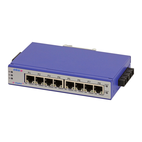
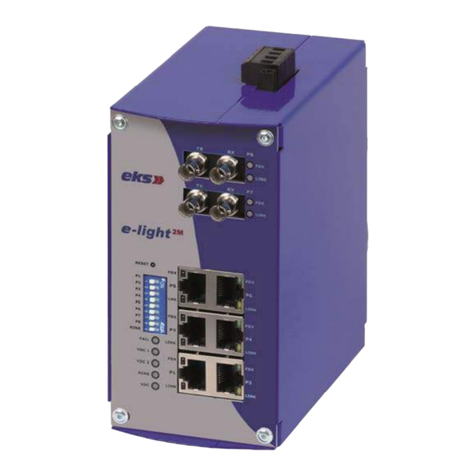
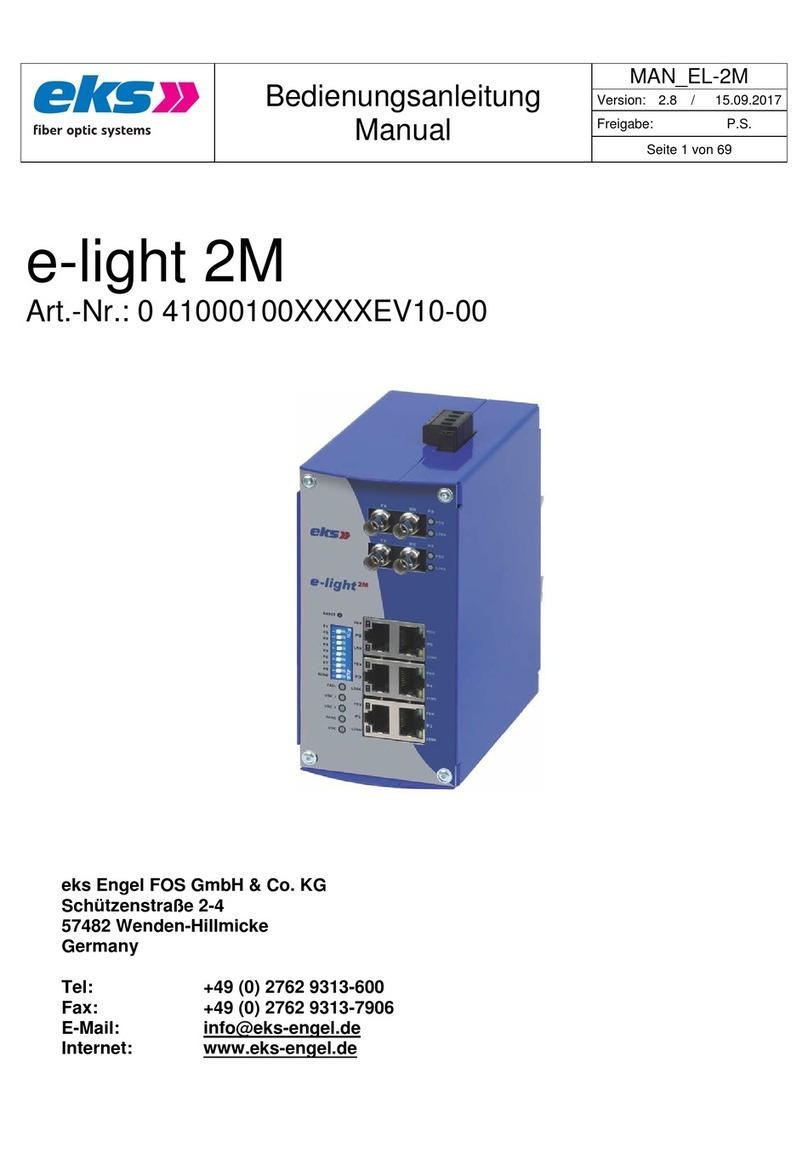
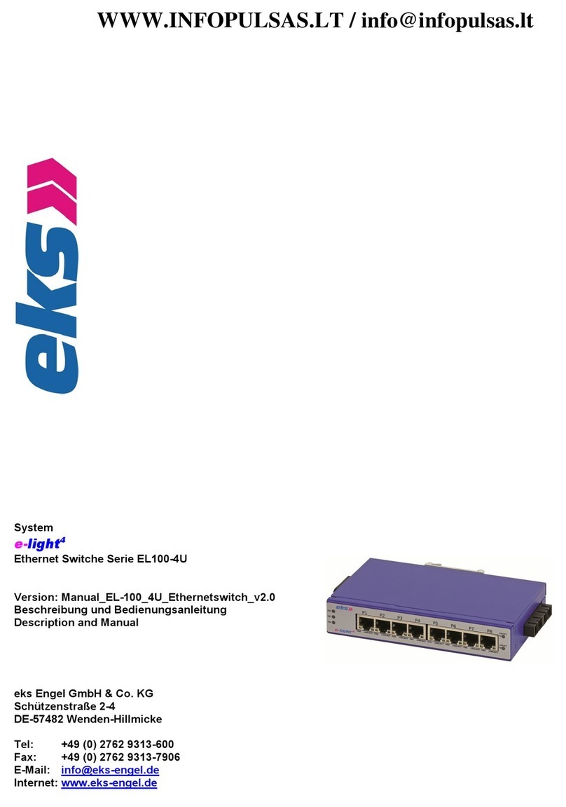
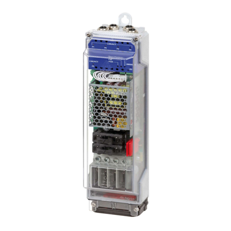
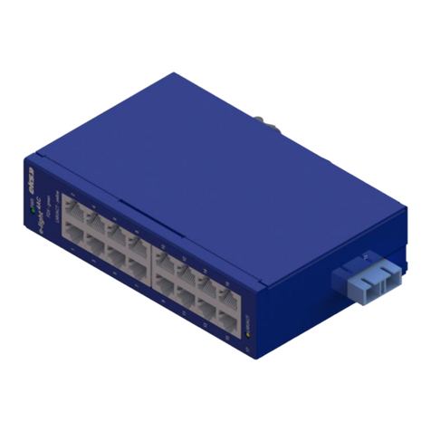
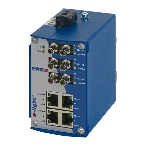
Die Serie EL1000-2G umfasst 7-Port Unmanaged Industrial Ethernet Layer 2
Switche für 10/100/1000 MBit/s mit 3xTX + 4xFX und 5xTX + 2xFX Ports. Sie
zeichnen sich durch einfache Funktionalität und Bedienfreundlichkeit wie
Autonegotiation und Auto MDI/MDIX aus.
Die kompakte Bauform im industriellen Design zeichnet sich vor allem durch
ihre hohe Flexibilität bei der Konfiguration aus. So können mit bis zu 4 FX-Ports
beliebig bestückt werden. Als optische Anschlussvarianten stehen neben SC
auch E-2000® zur Verfügung. Alle Systeme können sowohl über zwei Fasern
als auch über eine Faser durch BIDI-Technik mit SC-Anschluss kommuni-
zieren.
Als wichtige Leistungsmerkmale der Übertragung mit Kunststofffaser-,
Multimode- oder Singlemode-Lichtwellenleitern gelten die Unempfindlichkeit
gegenüber elektrischen und magnetischen Störungen, die Potenzialtrennung
von Sender und Empfänger sowie Reichweiten bis zu 40 km zwischen zwei
LWL-Systemen. Leds und optional potenzialfreie Kontakte eines Fehlerrelais
signalisieren fehlerhafte Zustände.
The series EL1000-2G contains 7-Port Unmanaged Industrial Ethernet Layer
2 Switches for 10/100/1000 MBit/s with 3xTX + 4xFX and 5xTX + 2xFX ports.
They are characterized by simple functionality and ease of use. Additional
features are Auto-Negotiation and Auto MDX/MDIX.
The rugged and compact housing allows a flexible FX-Port configuration. Up to
4 FX-Ports are available, each having a SC or an E-2000® fiber optic
connector. All systems can communicate via two as well as one fiber with the
help of the BIDI-technology with SC port.
Important performance features of the transfer with POF, multimode
or singlemode fiber optic are the electromagnetic ruggedness, the potential
separation of transmitter and receiver, as well as ranges up to 40 km between
two fiber optic systems. LEDs and potential-free contacts (optional) of a fault
detector relay are able to signal defective states.
Anschlusshinweise Hardware Installation
Achtung: Beim Betrieb elektrischer Betriebsmittel und Anlagen stehen
zwangsläufig bestimmte Teile unter gefährlicher Spannung. Arbeiten an
elektrischen Anlagen oder Betriebsmitteln dürfen nur von einer Elektro-
fachkraft oder von unterwiesenen Personen unter Anleitung und Aufsicht
einer Elektrofachkraft, den elektrotechnischen Regeln entsprechend, vorge-
nommen werden.
Schalten Sie die Systeme und Endgeräte spannungsfrei.
Rasten Sie das Gerät auf eine Tragschiene DIN EN auf, oder nutzen Sie die
Wandhalterung. Überprüfen Sie den sicheren Halt!
Achtung: Benutzen Sie nur die zugehörigen LWL-Anschlussstecker. Wir
weisen ausdrücklich daraufhin, dass der Anschluss mit falschen Steckver-
binder Schäden an den optischen Anschlüssen hervorrufen kann! Beachten
Sie zudem, dass die Stecker, die eine Verriegelung besitzen, nur in einer
definierten Position montiert werden können.
Achtung: Sehen Sie nicht in den optischen Sender! Das gebündelte und
abhängig von der Wellenlänge sichtbare oder unsichtbare Licht kann zu
Augenschäden führen!
Verbinden Sie den ankommenden Lichtwellenleiter mit dem optischen Emp-
fänger und den abgehenden LWL mit dem optischen Sender des LWL-
System.
Benutzen Sie die beigefügten Stopfen, um Sender und Empfänger des LWL-
Systems im nicht eingebauten oder nicht benutzten Zustand vor Verunreini-
gungen oder Staub zu schützen.
Achtung: Knicken Sie das LWL-Kabel nicht zu stark und beachten Sie den
Biegeradius des Kabelherstellers. Andernfalls kann das Kabel beschädigt
werden und/oder die Kommunikation zwischen den LWL-Wandlern nicht
mehr gewährleistet werden.
Schalten Sie die Betriebsspannung für die LWL-Systeme ein. Zur Versorgung
der Systeme wird eine Betriebsspannung von 12-65 VDC benötigt, die an
die Klemmen VDC1, VDC2 und GND angelegt wird. Das System hat einen
Verpolungsschutz.
Achtung bei Systemen mit BIDI: Bei Verwendung von Systemen mit optisch-
em BIDI-Anschluss müssen immer die optischen Anschlüsse (Transceiver)
vom Typ A mit Typ B verbunden werden.
Funktion der Status-Leds:
•VDC: Versorgungsspannung liegt an VDC1 oder VDC2 an
•FDX (grün): leuchtet wenn der Port im Fast Ethernet Modus
arbeitet
•Link/RX (gelb): blinkt bei Datenverkehr auf dem Port
Fehlerrelais (optional):
An Klemmen K1, K2, K3 und K4 befindet sich jeweils ein potentialfreier
Fehlerrelaiskontakt. Das Fehlerrelais fällt ab, wenn am VDC-Eingang keine
Versorgungsspannung anliegt.
Funktion der Kontakte K1 - K2: Fehlerrelaiskontakt geschlossen im Fehlerfall
Funktion der Kontakte K3 - K4: Fehlerrelaiskontakt geschlossen im Fehlerfall
Die Systeme der Serie e-light 2G verfügen über Auto-Negotiation und Auto
MDI/MDIX.
Attention: During operation of electrical equipment and systems, parts carry
dangerous voltages. Work on the electrical systems or equipment is only
allowed by a skilled electrician himself or by specially instructed persons
under the control and instructions of a qualified electrician and the
compliance of the electro technical regulations.
Power off the devices, which will be connected by using the fiber optic system.
Snap the system onto the DIN EN rail or use the wall mount. Check the correct
holding!
Attention: Only use the correct optical connectors for the fiber optic system.
Using incorrect connectors can cause damage to the fiber optic system.
Take care that connectors with a latch can only be mounted in a defined
position.
Attention: Don't stare into the optical cable or the transmitter of the fiber optic
system. Visible and non visible light (depending on its wavelength) of the
optical transmitter can cause eye-damages!
Connect the fiber optic system by using the correct fiber optic cable. Take care
that you always have to connect an optical transmitter and an optical
receiver.
Use the plugs to save the unused optical receiver and transmitter against
impurity.
Attention: Don't bend the fiber optic cable! Please refer to the manufacturer’s
specifications. Otherwise the fiber optic cable can be damaged and/or the
communication will be disturbed.
Power on the devices. Please use a power supply of 12-65 VDC, connected to
the terminals marked with VDC1, VDC2 and GND. Note, that the system has
a reverse voltage protection.
Attention: BIDI Switches must always be connected from transceiver type A
to a transceiver type B.
Status-LEDs:
•VDC: operating voltage connected to VDC1 or VDC2
•FDX (green):lights when the port is working in fast Ethernet mode
•Link/RX (yellow):flashes during data transfer on the port
Failure relay (optional):
There are two potential free failure relay contact at K1, K2, K3 and K4. The
relay switches if there is no supply voltage at the VDC input.
Function of K1 – K2: Failure relay contact, closed in case of failure
Function of K3 – K4: Failure relay contact, closed in case of failure
All switches of the series feature Auto-Negotiation und Auto MDI/MDIX.
