Bedienungsanleitung
Manual
Version: 2.0.2 / 19.09.2017
Freigabe: M.L.
Seite 3 von 4
Anschlusshinweise / Hardware Installation
Systembeschreibung System description
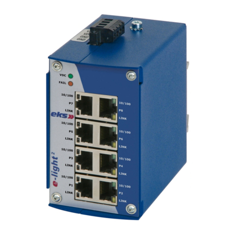
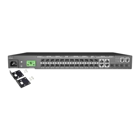
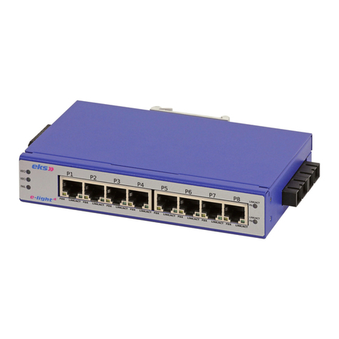
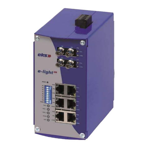
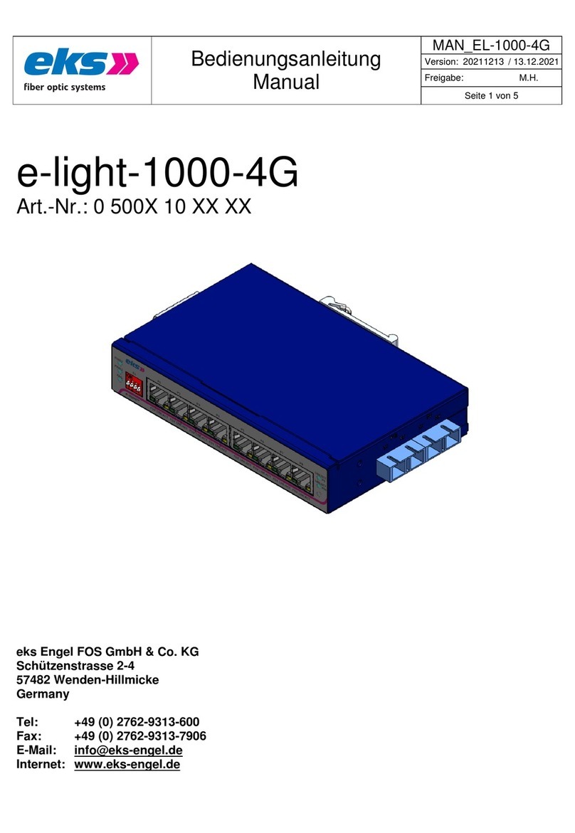
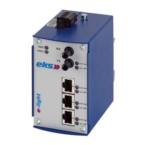
Die Geräte der e-light 2MA-Produktfamilie sind industrielle Ethernetswitches mit Ma-
nagement, die über eine Web-Applikation einfach und komfortabel konfiguriert wer-
den können. Sie ermöglichen eine kostengünstige Installation von industriellen
Ethernet Bus-, Stern- und Ringstrukturen mit Switching-Funktionalität.
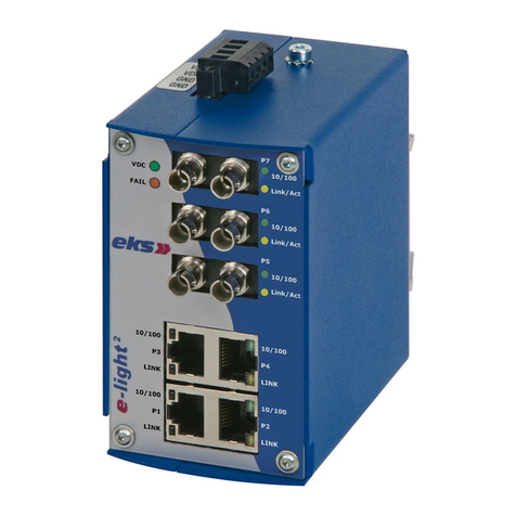
Neben einer Basisversion der e-light 2MA, die ohne Lichtwellenleiteranschlüsse aus-
geliefert wird, gibt es Versionen mit zwei oder vier Lichtwellenleiteranschlüssen. Die-
se Geräte können mit unterschiedlichsten Transceivern für Singlemode-, Multimode
oder HCS-Faser sowie POF ausgestattet werden. Je nach Faser können Transceiver
mit den Steckertypen ST, SC, E2000, SMA oder FC eingesetzt werden. Für POF
stehen außerdem Transceiver mit Klemmverbindung zur Verfügung, mit der POF
ohne Aufwand am Einsatzort der Switches konfektioniert und verbunden werden
The devices of e-light 2MA family are managed industrial Ethernet switches and can
be configured easily and comfortable via a web application. They allow cost-effective
installation of industrial Ethernet Bus-, Star- and ring structures with switching-
functionality.
In addition to a basic version of the e-light 2MA which is delivered without optical fiber
connections, there are versions with two or four fiber optic ports. These units can be
equipped with transceivers for singlemode-, multimode, HCS-fiber or POF.
Depending on fiber Transceiver with the connector types ST, SC, E2000, SMA or FC
can be used. Furthermore POF-transceivers with terminal connection are available.
So POF can be assembled and connected with no effort at the application site of the
switches.
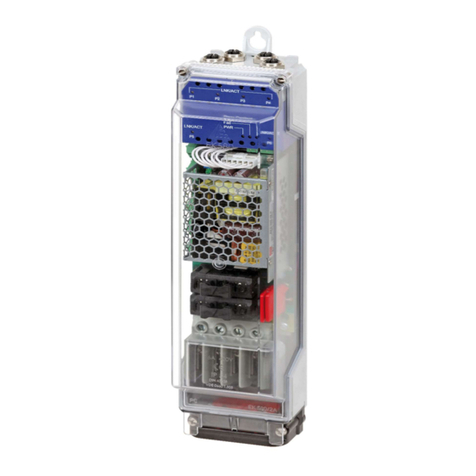
Status-LEDs / Status LEDs Fehlerrelais / Fault relay
Status:
VDC1 (grün/green): Spannung an VDC1 vorhanden. /
Power input at VDC1
VDC2 (grün/green): Spannung an VDC2 vorhanden. /
Power input at VDC2
RING (grün/green): Der Switch ist Manager in der Ringgruppe /
The switch is the manager of the ring group
Status (rot/red): Derzeit keine Funktion /
No function at the moment
Fault (rot/red): Spannungsausfall, Portfehler oder konfiguriert-
er Alarm aktiv. /
Voltage breakdown, port error or configured
alarm active
Ethernet Port:
FDX (grün/green): ON: Vollduplex-Betrieb/
Full duplex operation
OFF: LNK/ACT on: halbduplex /
Half duplex
LNK/ACT off: keine Verbindung /
No connection
LNK/ACT (gelb/yellow): Verbindung vorhanden (leuchtend) oder Daten-
verkehr (Blinken) oder keine Verbindung (off) /
Link (continuous light) or activity (blinking) or
no connection (off)
Fiberview:
LNK/ACT (grün/green): Datenverbindung (Leuchten) oder –verkehr
(Blinken) oder keine Verbindung (off) /
Link (Continuous light) or Activity (Blinking) or
no connection (off)
LIMIT (gelb/yellow): Niedriger Signalpegel /
Low signal level
FAIL: (rot/red): keine Verbindung /
no connection
Anschluss des Fehlerrelais:
An den Klemmen K1/K2 und K3/K4 befindet sich jeweils ein potentialfreier Fehlerre-
laiskontakt. Die Relais dienen als Alarmempfänger und können in der Software mit
verschiedenen Alarmauslösern verknüpft werden. Sie öffnen dann je nach
Konfiguration zum Beispiel bei einem Spannungsausfall, RJ45-Port Fehler oder
einem LWL-Port Fehler. In der Software wird das Relais zwischen K1 und K2 mit
Relais 1 bezeichnet und das Relais zwischen K3 und K4 mit Relais 2.
Connecting the fault relay:
There is a potential free differential relay contact at each clamp K1/K2 and
K3/K4. The relays are used as alarm receiver and can be linked in the software
with several alarm triggers. Depend on the configuration they will open, if there
is a voltage breakdown, a RJ45-port error or a fiber optic port error for example.
In the software the relay between K1 an K2 is named relay 1 an the relay
between K3 and K4 is named relay 2.
Die Belastbarkeit der Relaiskontakte liegt bei 25 VDC (1 A) bzw. 60 VDC (0,3 A) /
The capacity of the fault relay contact is 25 VDC (1 A) or 60 VDC (0,3 A)
Spannungsversorgung / Power supply
VDC1 / VDC 2 : Versorgungsspannung 12 bis 60 VDC / Supply voltage 12 to 60 VDC
GND: Versorgungspannungsmasse / Power supply ground
POF-Verbindung / POF-connection Abmessungen / Dimension
POF-Verbindung:
Um das POF-Kabel mit dem Optolock zu verbinden, wird das Kabel zunächst sauber
abgeschnitten. Mit dem POF-Schneidwerkzeug wird das Kabel an der gewünschten
Stelle mit einem geraden Schnitt im 90°-Winkel getrennt. Die Enden der beiden
Fasern werden anschließend separiert. Jede Faser wird dann in eines der beiden
Löcher des Transceiver Gehäuses eingeführt und der Verschluss wird
zusammengepresst, um die POF-Faser in Position zu halten.
Beachten Sie bei der Verarbeitung von Lichtwellenleitern deren Biegeradius und den
Temperaturbereich der eingesetzten Stecker.
HINWEIS: Ein Dokument mit weiteren Hinweisen zur Verarbeitung von POF-Kabeln
und Transceivern finden Sie unter www.eks-engel.de/unternehmen/downloads/.
POF-connection:
To connect the POF cable into the Optolock, the end of the cable is cut cleanly. Use
a POF-Cutter to make a straight cut in an angle of 90° at the chose position of the
cable. After that the end of the two strands are separated. Then the strands are
inserted into the two holes in the termination housing, which is then pressed close to
hold the POF in place.
Pay attention on the bending radius of the optical cables while installing them and
check the temperature range of the used plugs.
PLEASE NOTE: You can find a document with remarks concerning the handling of
POF-Cable and Transceiver on www.eks-engel.de/unternehmen/downloads/.

