El-Björn A 155F User manual

User instructions
WARNING!
400V
VARNING!
FÅREJ ÖVERTÄCKAS
OBS!
BYTFILTER
REGELBUNDET
Drying room dehumidier
A155F/A155HW

Table of contents ........................................................ 2
Introduction ........................................................ 3
Technical data ........................................................ 3
Safety instructions ........................................................ 4
Description ....................................................................... 5-9
Installation ....................................................................... 10-13
Drying ....................................................................... 14-15
Maintenance ....................................................................... 16-17
Spare parts/accessories ........................................................ 18
TABLE OF CONTENTS
- 2 -

4
INTRODUCTION
TECHNICAL DATA
- 3 -
Technical data, dehumidier
Width: 470 mm
Height: 1498 mm
Depth: 370 mm
Noise level: 66dB
Weight: 70 kg
Electrical connection: 3N~400V
Fuse: 10 A slow
Rated power (A 155F): 5400W
Rated power (A 155HW): 1200W
Auxiliary heating: 3990W
Operating range, temp.: 15-35ºC
Operating range, RH: 35-99%
Dehumidication capacity: Max. 3 l/h
Refrigerant, type: R134a
Refrigerant, amount: 870g
The A 155 dehumidier is designed for the high
capacity drying of laundry in large drying rooms, for
example in apartment / multi occupancy buildings
or on site Portacabins. An optional pipe system
for hanging laundry on can be ordered with the
dehumidier. See web site for more information
This instruction manual covers the free-blowing
dehumidiers A 155F (standard electric) and the
155HW (hot water), model designed for district
heating.
The manual contains detailed instructions for use,
maintenance and inspection of the dehumidier with
or without a pipe system. It includes instructions for
insuring maximum safety and information on the
design and use of the safety features.
NOTE: All persons using or repairing the
dehumidier should carefully read the section
on safety.
This manual contains instructions on use of the
product and maintenance that can be carried out by
the operator.
More detailed servicing or troubleshooting may only
be performed by the manufacturer’s service staff or
representative.
The user instructions describe all the necessary safety
features.. The rst thing the user should do following
delivery, is to read the instruction manual carefully.
This should be done before connecting to the
electricity supply.
The manufacturer reserves the right to make
modications.
Various symbols and warning signs are shown in
this manual and displayed on the dehumidier.
They are listed on the next page.
If any of the warning signs on the dehumidier
are damaged in any way, a new one must be
ordered and attached immediately to ensure
maximum safety during use of the dehumidier.
The dehumidier may only be used for the
applications described in this user manual.
The manufacturer reserves the right to make any
modications.

5
SAFETY INSTRUCTIONS
- 4 -
Warning signs on the dehumidier
Read the instruction manual carefully
before using the dehumidier.
Warning of high voltage if the hatch is
opened before the power supply to the
dehumidier has been turned off.
The manufacturer’s guarantee that this
product meets the safety provisions of
the Low Voltage Directive.
Safety during installation
Electrical connection of the dehumidier and its peripheral
equipment should be carried out by a qualied electrician.
Safety during use
The dehumidier’s air intake and air outlet must never
be covered during operation. It is strictly forbidden
to remove the protective hoods or cover plates during
operation.
Safety during maintenance
The power supply to the machine must be cut off
before performing maintenance on the dehumidier.
This can be done by pulling the connector out of
the power socket, or by breaking the current with the
circuit breaker.
All maintenance of the electrical system must be
performed by a qualied electrician.
All maintenance of the refrigeration system must be
performed by a qualied refrigeration technician.
When cleaning the condenser and evaporator, use
gloves to avoid cutting injuries.
Caution! and Note:
The following boxes are shown in this instruction
manual where appropriate.
CAUTION!
These boxes warn of injury or
damage to people or objects.
The caution boxes are shown in front
of the procedure they refer to.
NOTE:
These boxes contain special
instructions and information on how
to make specic procedures easier.
The lter should be
replaced 1–2 times per
year. Also see under
“Maintenance”.
The dehumidier’s air
intake and air outlet
must never be covered.
Warning signs in these user instructions
Read the instruction manual carefully
before using the dehumidier.
Caution! The dehumidier may be
dangerous. Careless or incorrect use
could result in serious or even fatal
injury.
The manufacturer’s guarantee that this
product meets the safety provisions of
the Low Voltage Directive.
VARNING!
400V • The product may not be used by persons (including
children) with physical or mental disabilities,
unless they have received information or instruction
on safe use of the product from a person with
responsibility for their safety.
• However, the product is suitable for use in
environments where there are persons (including
children) with physical or mental disabilities or
impaired judgement.
• If children have access to the product, they must be
instructed not to use the product for playing with.
1-2 times / year
604503

DESCRIPTION
- 5 -
WARNING!
400V
VARNING!
FÅREJ ÖVERTÄCKAS
OBS!
BYTFILTER
REGELBUNDET
1
2
16
AEV
9
LP
M2
10
12
K2
K1
X
S1
GT3
GT2
GT5
1 Ceiling mounting with suspension bars.
2 Side bar
3 Drying pipes
4 Base pipe
5 End plate
6 Inner telescopic tube
7 Outer telescopic tube
8 Anti-tip device
9 Drain water connection, for copper pipe Ø15 mm
10 Adjustable foot
12 Type plate
13 Sticker “Replace lter regularly”
14 Filter cassette (inside door)
15 Sticker “Do not cover”
16 Hanger (accessory)
B1 Overcurrent relay
AEV Evaporator. (Also see next page).
E Auxiliary heating 3990 W. (1330x3)(See next page or
water condenser A 155HW
FT Dryer lter. (See next page).
GT1 Thermostat for control of heating coil
GT2 Overheating protector, manual reset (x 2).
GT3 Overheating protector, automatic reset GT4
Thermocontact switch in fan (not shown).
GT5 Low pressure control
GT6 Overload protection device, compressor
GT7 Overload protection device, compressor
K1 Contactor for fan
K2 Contactor for compressor
K3 Contactor for heating coil
KD Capacitor. (See next page).
M1 Fan. (See next page).
M2 Compressor
S1 Timer, 2 options
X Terminal block
SD Capillary tube, throttle (see next page).
LP Low pressure control
GT1
B1
K3
3
5
4
6
7
8
15
13
14
Fig 1. A 155 with pipe system
GT6/GT7

DESCRIPTION
- 6 -
Function
Dehumidier A 155
The A 155 is a condensation dehumidier, and is
based on the principle that air moisture condenses on
cold surfaces.
The cold surfaces are created on the evaporator
(AEV) when the compressor (M2) transfers heat from
the evaporator to the condenser (KD).
The dehumidier is equipped with a fan (M1) that
transports the air through the dehumidier.
The air rst passes through the evaporator (AEV),
where the moisture condenses and is deposited on the
evaporator.
The condensate collects in a trough located
underneath the evaporator, is transported away.
The air then passes through the fan (M1) and the
condenser (KD). In the condenser, the air is warmed
up and the condenser is simultaneously cooled.
After this, the air can be heated by the auxiliary
heating system (E) before being released from the
dehumidier.
Pipe system
The pipe system has two functions: it distributes the
air and is used for hanging washing on. The diameter
of the drying pipes is(Ø60 mm) (3) prevents clothes
from creasing whilst drying.
Dry air from the dehumidier is blown into the pipe
system and distributed to the drying pipes (3) via the
base pipe (4).
Dry air is blown downwards through holes in the
drying pipes, and is distributed between the items of
laundry.
This dries the laundry evenly, even in the places that
are least exposed.
All tubes are made of extruded, anodised aluminium,
making them highly durable and corrosion-resistant.
E
KD
M1
FT
SD
A
AEV
M2
Moist air
43
Moist air
Dry air
Dry air
Fig 3. A 155F (left) and A 155 with pipe system

Principle diagram, pipe A 155
Components
KD Condenser
MU Measurement socket
FT Dryer lter
M1 Fan
M2 Compressor
AEV Evaporator
SD Capillary tube, throttle
A Accumulator
LP Low pressure control
Electrical system
Function
Instructions on connecting the control unit/timer can
be found under “Installation”.
When the timer (S1) is activated, the following occurs:
1. The contactor (K1) is activated and starts the fan
(M1) and the auxiliary heating (E).
2. K2 is activated via GT5 and starts the compressor
(M2).
3. When the temperature has risen to the set value,
GT1 cuts off the power to the auxiliary heating (E).
4. The temperature is regulated by the thermostat
(GT1), which, if necessary, connects the heating coil
(E) according to the set value.
5. When the temperature of the evaporator sinks,
there is a risk of ice crystals forming. If ice forms, LP
breaks the current to K2 and the compressor stops.
6. When the timer cuts out, the dehumidier stops
running.
Compressor (M2)
e compressor has two separate external motor
guards (GT6 and GT7). e motor guard function
(TK) is also built into the motor windings, stopping
the motor if it overheats. e function resets
automatically when the temperature returns to
normal.
Termal overload relay (QF1)
Protects the compressor from overload (Set value:
2.5A). It breaks the current to the whole machine if it
is activated.
Low pressure control(LP)
Breaks the current to the compressor if the
temperature is too low or if the refrigerant runs out.
Fan (M1)
The fan motor has no separate motor guard.
Instead, it is equipped with a thermocontact switch
(GT4). The thermocontact switch is located inside
the motor winding, and breaks the current if the
motor overheats. The thermocontact switch resets
automatically when the temperature returns to normal.
A capacitor is used to ensure correct fan function.
Thermostat (GT1)
GT1 controls the auxiliary heating (E) and can be set
from 0-9 (equivalent to approx. 0-40°C).
Overheating protector A 155F (GT2:1
and GT2:2)
GT2:1 and GT2:2 are two thermocontacts inside
the heating coil (E). GT2:1 and GT2:2 break the
current at 90°C. They must be reset manually when
the temperature has dropped. See the section on
maintenance.
Overheating protector A 155F (GT3)
GT3 is an overheating protector inside the heating
coil. It breaks the current to C3 at 70°C. GT3 resets
automatically when the temperature has dropped.
DESCRIPTION
- 7 -
0
1
2
3
4
5
6
7
8
9

DESCRIPTION A155F
- 8 -

- 9 -
DESCRIPTION A155HW

The dehumidier can be ordered and delivered with
or without a clothes drying pipe system. After delivery,
the pipe system should be installed according to the
instructions on this page.
The pipe system can be ordered separately.
Room size
The room in which the pipe system is installed must
have the following dimensions:
Pipe assembly Base pipe, L Drying pipe, quantity x L Room, W x L
1 2500 mm 12 x 2500 mm 2.7 x 2.9 m
2 2500 mm 12 x 3000 mm 2.7 x 3.4 m
3 2000 mm 10 x 3000 mm 2.2 x 3.4 m
Tools
If the pipe system is installed in a room with concrete in
the walls and ceilings, the following tools are needed:
• Tape measure
• Water level
• Hammer drill 12 mm drill bit
• Spanner 13 mm
• Cross-head screwdriver
• Hack saw
Base pipe
1. Use a water level and tape measure and mark the
position of the wall mountings.
Recommended height: 1700 mm
Min. height: 1700 mm
Mex. height: 1850 mm
The wall mountings can be slid along the base pipe,
and should be positioned roughly 300 mm from the
ends of the base pipe.
2. Drill the holes with the hammer drill and a 12 mm
drill bit and screw the ceiling mountings into place
with the screw holes facing downwards.
3. Attach the inner telescopic tube to the base pipe
with the six sheet metal screws. The joint on the
telescopic tube should be turned backwards (against
the wall when the base pipe is installed).
4. Suspend the base pipe on the wall mountings and
secure it with the included screws.
CAUTION!
Use a respirator and protective
goggles when performing hammer
drilling, especially in the ceiling.
INSTALLATION
C145 mm / 360 mm
A
WARNING!
400V
VARNING!
FÅREJ ÖVERTÄCKAS
OBS!
BYTFILTER
REGELBUNDET
1700 mm
(1700 mm - 1850mm)
BL
- 10 -
INSTALLATION OF PIPE SYSTEM

Dehumidier
1. Lubricate the rubber strip with dishwashing liquid
or soft soap. Thread the outer telescopic tube (7)
onto the inner telescopic tube (6). Push the tube
up as far as it will go.
2. Position the dehumidier (AF) with the air outlet
centred underneath the telescopic tubes.
3. Push the outer telescopic tube (7) down into the
dehumidier (AF) and fasten with the six sheet
metal screws.
4. Continue installing the dehumidier according to
the instructions on the next page.
Drying pipes
1. Carefully bend the base pipe (4) and remove the
mounting bar (MS), see g. A.
2. Fit together the drying pipes (3), mounting bar
and side bar (2). Using the cross-head screwdriver,
attach each drying pipe (3) with six sheet metal
screws (included), see gs. B and C.
3. Place the lower edge of the mounting bar, along
with the attached drying pipes, in the base pipe.
4. Carefully lift the side bar (2) so that the mounting
bar snaps into the base pipe, see g. C. Fix the
side bar into the rods in the ceiling mountings.
5. Tighten the screws in the ceiling mountings.
6. Cut the rod to size if it is too long.
7. Install the end plates on the base pipe with 4 sheet
metal screws in each plate.
2. Drill the holes using the hammer drill with a 12 mm
drill bit and screw the ceiling mountings into place.
3. Attach the ceiling mountings (see picture). Attach
the screws loosely so they can be adjusted when the
drying pipes are installed.
Cealing mountings
1. Mark out the position of the ceiling mountings (1)
using a tape measure, See the dimension table below
and the gure on the previous page.
Dimension table
If drying pipes are used Distance from wall, A
L=2500 mm 2695 mm
L=3000 mm 3195mm
If base pipe is used Distance from outer ends of
base pipe, C
L=2000 mm 145 mm
L=2500mm 360 mm
6
7
AF
MS
3
2
3
1
4A
B
C
MS
INSTALLATION
- 11 -

Dehumidier
Unpackning
Before installing the dehumidier, unpack and check
the parts listed below. The parts are in a bag inside the
hatch (L).
• Four adjustable feet.
• Two anti-tip devices.
• Three cable glands with nuts.
• Clamp connection
Assembly
Assemble the dehumidier horizontally on a at,
stable surface next to a wall. Attach and adjust the feet
until the dehumidier is standing horizontal.
Attach the two anti-tip devices on either side between
the dehumidier and the wall.
Condensate
The dehumidier has a condensate outlet. Fit the
included clamb connection in the outlet and connect
a pipe Ø15 mm. Screw the pipe into place so that it
points down towards a oor drain.
Hot water connection A 155HW
Connect the inlet to the upper 15 mm pipe.
Install an external solenoid valve here to regulate the
ow.
It is regulated by a thermostat (GT1) in the
dehumidier. Connect it to 7-8 in the terminal strip.
External circulation fans (accessory)
One or more external fans can be installed to
increase air circulation. (Not necessary if a pipe
system is installed.) If there are other circulation
fans in the drying room, they must not blow air
directly onto the dehumidier’s inlet or outlet.
INSTALLATION
L
VARNING!
FÅR EJ ÖVERTÄCKAS
WARNING!
400V
OBS!
BYTFILTER
REGELBUNDET
VARNING!
FÅREJ ÖVERTÄCKAS
WARNING!
400V
OBS!
BYTFILTER
REGELBUNDET
VARNING!
FÅREJ ÖVERTÄCKAS
WARNING!
400V
OBS!
BYTFILTER
REGELBUNDET
- 12 -

Electrical connection
CAUTION!
Electrical connection of the
dehumidier and its peripheral
equipment should be carried out by a
qualied electrician according to
national installation regulations.
Timer with mechanical upward adjustment
(accessory)
Install the timer in a suitable place in the drying room
and wire it as follows:
• Use cable with min. area of 0.75 mm2.
• Connect outlets 1 and 3 in the timer to outlets
3 and 4 on the terminal block (X) in the
dehumidier.
Timer with preset time (accessory)
Install the timer in a suitable place in the drying room
and wire it as follows:
• Use cable with min. area of 0.75 mm2.
• Connect the timer’s outlets to the corresponding
outlets on the terminal block (X) in the
dehumidier.
3 4
3N~400V
X
N
N
3 4 N 5 6L
1
L
2
L
3
0
1
2
3
4
INSTALLATION
- 13 -
Connect the dehumidier via the circuit breaker to
3N~400 V and earth. Fuse with at least a 10A slow
fuse. Connect to the terminal block (X). Use a cable
equivalent to (A05RN-F) 5x1.5 mm2.
3 4
3N~400V
X
N
N 3 4 N 5 6L1L2L3

0
1
2
3
4
CAUTION!
The dehumidier’s air intake and air
outlet must never be covered during operation.
It is strictly forbidden to remove the protective
hoods or cover plates during operation.
Timer
The dehumidier is equipped with one of the
following timers:
• Mechanical upward adjustment.
• Preset time.
If the dehumidier has a timer with preset time, set
the desired time as follows:
1. Break the current to the drying room dehumidier
with the circuit breaker.
2. Open the timer’s lid and set the cycle time (factory
set to 2.5 hrs) using knob B, which is calibrated in
hours.
Adjust the cycle time on the time relay as follows:
1. Knob A to the position “1-10 h” (1-10 hours).
2. Knob B to the position “2.5” (2.5 hours
recommended).
3. Knob C to position “C”.
4. Replace the lid and connect the dehumidier to
the power using the circuit breaker.
Start
Timer with preset time
Press the start button (B) and the dehumidier will
run for the set cycle time.
If the start button is pressed during operation, the
cycle time will restart from zero.
The dehumidier can be stopped by pressing the stop
button (C).
D
Start
Timer with mechanical upward adjustment
Turn the timer knob (D) to the desired start time.
NOTE:
Never turn the timer knob backwards without rst
turning it all the way forwards.
Important
B
C
A1 A2
1
2346789
10
0,1-1s
1-10s
6-60s
1-10min
6-60min
1-10h
2-20h
ON
Crouzet
16 18
15 Y1
EMER
H
W
D
PE A
B
C
R
DRYING
- 14 -
Knob ”A”
Knob ”B”
Knob ”C”

General advice on drying
Dehumidiers without a pipe system can have a pipe
system added later. A pipe system offers the following
drying advantages:
• The wide diameter of the tubes prevents creases
from forming on the laundry while drying.
• The dry air is blown underneath the drying pipes.
The air is distributed evenly through the laundry,
including the parts that are hard to reach, drying
the laundry from the inside out.
• Faster, cheaper drying.
• The drying pipes are stable and xed into place.
No drying room lines that hang down or risk
breaking
DRYING
- 15 -
OBSERVERA!
• Spin washing for at least 5 minutes before
hanging it to dry. The higher the spinning
speed, the shorter the drying time. Avoid
slow spinning if you have limited time for
using the drying room dehumidier.
• Distribute the washing evenly when hanging it
in the drying room.
• Keep doors and windows closed to prevent
damp air from entering the room.
5 min
CENTRIFUG
5 min
SPIN
Once assembled, the pipe system can be
supplemented with a separate suspended clothes
drying rack. The drying rack can be used for drying
small garments such as underwear, gloves and socks.

Every 6 months
Check every 6 months that the dehumidier is clean
inside.
CAUTION!
Use gloves when performing work
on the condenser and evaporator.
The sharp ns can cause cutting
injuries.
Perform the following operations as necessary:
• Replace the lter cassette. 1-2 times per year.
• Wash the ns of the evaporator (AEV) with
dishwashing liquid and water as necessary.
CAUTION!
The power supply to the machine must be cut off before performing
maintenance on the dehumidier. To do this, break the current with
the circuit breaker.
All maintenance of the electrical system must be carried out by an
authorised electrician.
All maintenance of the refrigeration system should be carried out by an
authorised refrigeration technician.
Once a year
Check the following points once a year. The points
must be checked by an authorised staff member.
• Clean the evaporator.
• Clean the drip pan and outlet.
• Check the bearings in the fan motor.
• Check all couplings.
• Check the refrigeration system, check for leaks.
• Check the electrical system.
MAINTENANCE
- 16 -

OBS!
BYT FILTER
REGELBUNDET
WARNING!
400V
KL604233
FK
FL
Overheating protector (GT2:1, GT2:2)
If the heating coil stops working, this may be because
the overheating protector (GT2:1 or GT2:2) has been
activated. GT2:1 and GT2:2 are positioned inside the
hatch (L), and are reset as follows:
1. Break the current with the dehumidier’s circuit
breaker.
2. Find out what triggered the overheating protector
and correct the fault. Possible causes are electrical
faults or poor air circulation.
3. Unscrew the dehumidier’s top hood (B) and
hatch (L). Reset the overheating protector(s) by
pressing the relevant button(s).
4. Attach the hatch and the hood and switch on the
power.
B
L
GT2:1
och
GT2:2
Replacing the lter
1. Undo the upper screws on the lter hatch (FL).
Pull the lter hatch outwards.
2. Pull out the lter cassette (FK). Insert a clean
lter cassette. The arrow on the lter cassette
should point in towards the machine.
3. Push the lter hatch inwards and tighten the
screws.
Repair
If extensive repair is necessary, contact your dealer.
Always contact the supplier if repairs are needed
during the warranty period.
MAINTENANCE
- 17 -
1-2times / year
604503

When ordering accessories, always specify the
following information:
• Type
• Serial number
This information is displayed on the dehumidier’s
type plate.
Pos Page Designation Quantity Item No.
3 7 Drying pipe, L=2500 mm 12 KL603115
3 7 Drying pipe, L=3000 mm 10 KL603106
4 7 Base pipe, L=1250 mm 1 KL603112
4 7 Base pipe, L=2000 mm 1 KL603100
4 7 Base pipe, L=2500 mm 1 KL603109
8 6 Anti-tip device 2 KL503210
9 6 Clamb connection 1 KL602070
10 6 Adjustable foot 4 KL503251
12 6 Type plate 1 SE9003-TR
15 6 Sticker “Do not cover” 1 KL604204
6 Cable gland M25 2 1477684
6 Nut for cable gland M25 2 1477633
6 Cable gland M16 1 1477682
6 Nut for cable gland M16 1 1477631
AEV 6, 7 Evaporator 1 KL400150
QF1 7, 8, 9 Therminal overload relay 1 3236515
E 7, 9 Heater, 1330 W 3 KL305040
FT 7 Dryer lter 1 KL401211
GT1 6, 9 Thermostat 1 KL304125
GT2: 1,2 9 Overheating protector 2 KL304236
GT3 6, 9 Overheating protector 1 KL304235
LP 6, 9 Low pressure control 1 1416580
K1-K3 6, 9 Contactor 3 3230604
KD 7 Condenser 1 KL400152
M1 7, 9 Radial fan 1 KL300303
Capacitor 7 uF (for radial fan) 1 KL300302
Capacitor 30 uF (for radial fan) 1 KL503252
M2 6, 9 Compressor 1 KL410110
SD 7, 8 Throttle, 1000 mm 2 KL405001
A 7, 8 Accumulator 1 KL401010
X1 6, 9 Terminal block, 2x2,4/6 mm white/grey 8 2930399
X1 6, 9 Terminal block, 2x2,4/6 mm blue 3 2930401
X1 6, 9 Terminal block, 2x2,4/6 mm yellow/green 2 2930402
Accessory
14 6 Filter cassette 2 -pack - E8745030
14 6 Filter cassette 6 -pack - E8745031
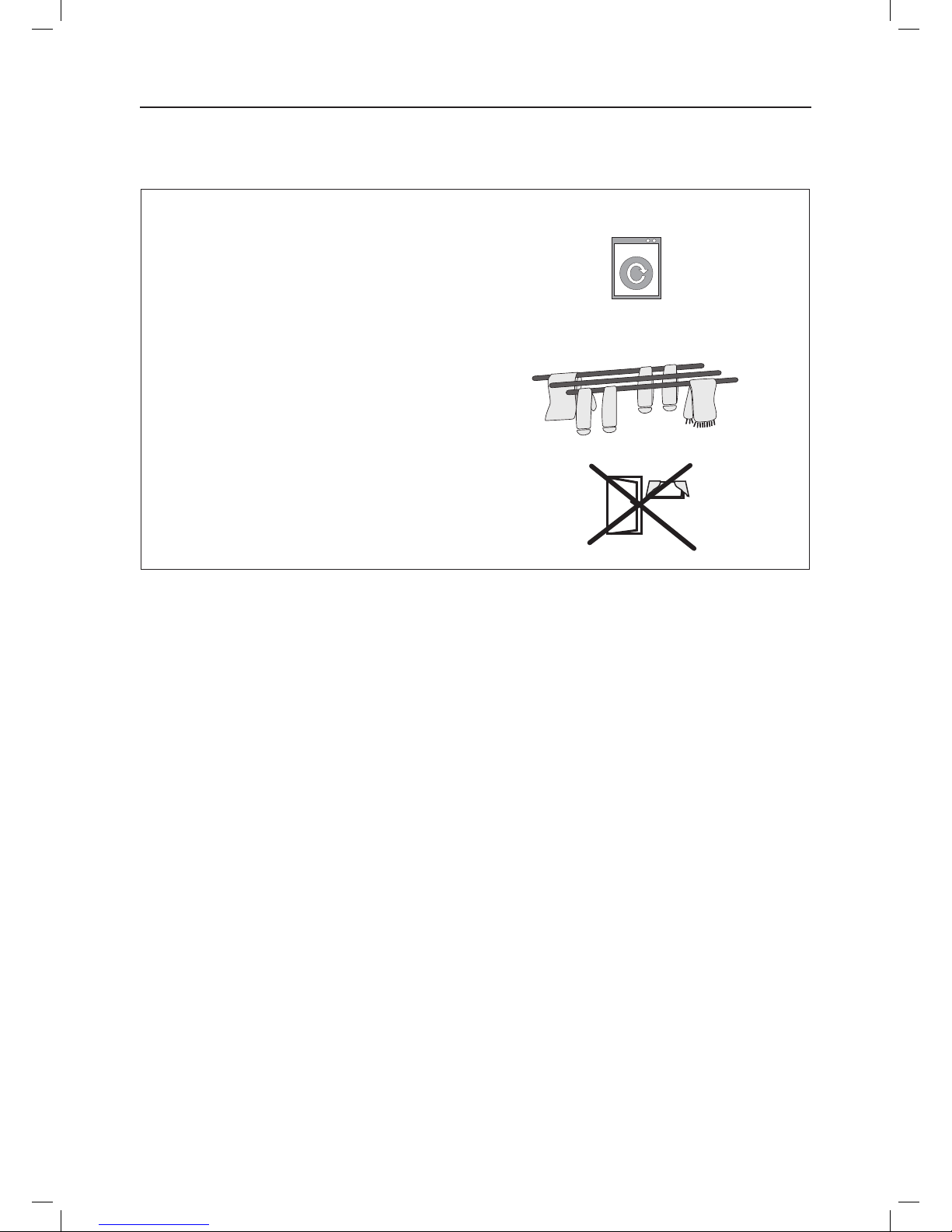
16 6 Hanger for pipe assembly, laundry hanger - E8745058
S1 6,13 Timer with mechanical upward adjustment 0-4 hrs - E8745050
S1 6, 13 Timer, electronic A 150 F/R - E8745051
S1 - Timer, electronic incl. hygrometer - E8745053
- - Transformer, 400/230V 300VA - KL303005
- 12 1 Circulation fan CF400V drying room - E8745055
- 12 1 Circulation fan CF230V drying room - E8745056
- Pipe system 2.5x2.5 M - E8745040
- Pipe system 2.5x3.0 M - E8745041
- Pipe system 2.0x3.0 M - E8745042
SPARE PARTS/ACCESSORIES
- 18 -
Pos indicates the position of the part in the gures.
Page indicates the page where the relevant gure is
shown.
Quantity species how many units of each part the
humidier contains

COMMENTS
...........................................................................................................
...........................................................................................................
...........................................................................................................
...........................................................................................................
...........................................................................................................
...........................................................................................................
...........................................................................................................
...........................................................................................................
...........................................................................................................
...........................................................................................................
...........................................................................................................
...........................................................................................................
...........................................................................................................
...........................................................................................................
...........................................................................................................
...........................................................................................................
...........................................................................................................
...........................................................................................................
...........................................................................................................
...........................................................................................................
...........................................................................................................
...........................................................................................................
...........................................................................................................
...........................................................................................................
...........................................................................................................
...........................................................................................................

El-Björn AB, Box 29, 334 21 Anderstorp, Sweden
Phone: +46 371 588 100, Fax: +46 371 181 34
[email protected], www.elbjorn.com
KL597007-GB/ 140116
Other manuals for A 155F
1
This manual suits for next models
1
Table of contents
Other El-Björn Dehumidifier manuals

El-Björn
El-Björn A 150 VTI User manual

El-Björn
El-Björn A 700VTI User manual

El-Björn
El-Björn RM85-H User manual

El-Björn
El-Björn A 155FS User manual

El-Björn
El-Björn A 75F/R User manual

El-Björn
El-Björn A 75FT User manual

El-Björn
El-Björn A 60 BT User manual

El-Björn
El-Björn AD 200S User manual

El-Björn
El-Björn A 75 BT User manual

El-Björn
El-Björn A 155F User manual